| Maintenance Service Interval | Maintenance Procedure |
|---|---|
| Before each use or daily |
|
Introduction
This machine is a ride-on, multi-purpose machine intended to be used by professional, hired operators in commercial applications. It is primarily designed for maintaining grass on well-maintained lawns in parks, sports fields, and on commercial grounds. It is not designed for cutting brush.
Read this information carefully to learn how to operate and maintain your product properly and to avoid injury and product damage. You are responsible for operating the product properly and safely.
You may contact Toro directly at www.Toro.com for product safety and operation training materials, accessory information, help finding a dealer, or to register your product.
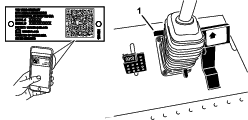
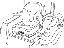
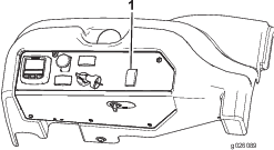
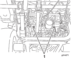
Whenever you need service, genuine Toro parts, or additional information, contact an Authorized Service Dealer or Toro Customer Service and have the model and serial numbers of your product ready. Figure 1 identifies the location of the model and serial numbers on the product. Write the numbers in the space provided.
Important: With your mobile device, you can scan the QR code on the serial number decal (if equipped) to access warranty, parts, and other product information.
This manual identifies potential hazards and has safety messages identified by the safety-alert symbol (Figure 2), which signals a hazard that may cause serious injury or death if you do not follow the recommended precautions.

This manual also uses 2 words to highlight information. Important calls attention to special mechanical information and Note emphasizes general information worthy of special attention.
Warning
CALIFORNIA
Proposition 65 Warning
Diesel engine exhaust and some of its constituents are known to the State of California to cause cancer, birth defects, and other reproductive harm.
Genuine Toro spark arresters are approved by the USDA Forestry Service.
It is a violation of California Public Resource Code Section 4442 or 4443 to use or operate the engine on any forest-covered, brush-covered, or grass-covered land unless the engine is equipped with a spark arrester, as defined in Section 4442, maintained in effective working order or the engine is constructed, equipped, and maintained for the prevention of fire.
The enclosed engine owner's manual is supplied for information regarding the US Environmental Protection Agency (EPA) and the California Emission Control Regulation of emission systems, maintenance, and warranty. Replacements may be ordered through the engine manufacturer.
Safety
This machine has been designed in accordance with ANSI B71.4-2012.
General Safety
This product is capable of amputating hands and feet and of throwing objects. Always follow all safety instructions to avoid serious personal injury.
Using this product for purposes other than its intended use could prove dangerous to you and bystanders.
-
Read and understand the contents of this Operator’s Manual before starting the engine.
-
Use your full attention while operating the machine. Do not engage in any activity that causes distractions; otherwise, injury or property damage may occur.
-
Do not put your hands or feet near moving components of the machine.
-
Do not operate the machine without all guards and other safety protective devices in place and working on the machine.
-
Keep clear of any discharge opening. Keep bystanders and pets a safe distance away from the machine.
-
Keep children out of the operating area. Never allow children to operate the machine.
-
Stop the machine, shut off the engine, remove the key, and wait for all moving parts to stop before servicing, fueling, or unclogging the machine.
Improperly using or maintaining this machine can result in injury. To reduce the potential for injury, comply with these safety instructions and always pay attention to the safety-alert symbol, which means Caution, Warning, or Danger—personal safety instruction. Failure to comply with these instructions may result in personal injury or death.
You can find additional safety information where needed throughout this Operator’s Manual.
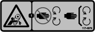
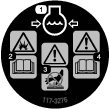
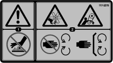
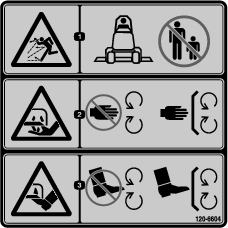
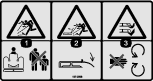
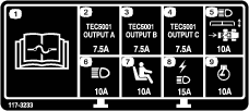
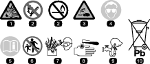
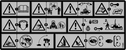
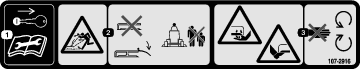
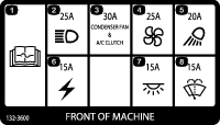
Safety and Instructional Decals
 |
Safety decals and instructions are easily visible to the operator and are located near any area of potential danger. Replace any decal that is damaged or missing. |


Setup
Installing the PTO Driveshaft to an Optional Mower Deck or QAS
Parts needed for this procedure:
| PTO driveshaft | 1 |
| Bolt (5/16 x 1-3/4 inches) | 4 |
| Locknut (5/16 inch) | 4 |
| Roll pin (3/16 x 1-1/2 inches) | 2 |
Note: Installing the PTO driveshaft is easier if you position the machine on a hoist.
-
Park the machine on a level surface, engage the parking brake, shut off the engine, and remove the key.
Warning
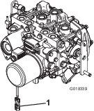
Do not start the engine and engage the PTO switch when the PTO driveshaft is disconnected from the cutting deck. If you start the engine and the PTO shaft is allowed to rotate, serious personal injury and machine damage could result. Before the PTO driveshaft is disconnected from the cutting deck, disconnect the PTO solenoid-valve-coil connector from the wire harness to prevent unintentionally engaging the PTO clutch.
-
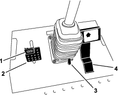
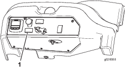
Disconnect the wire-harness connector from the PTO solenoid-valve-coil connector (Figure 3).
-
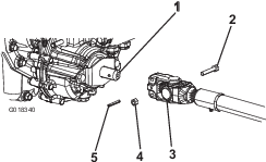
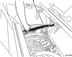
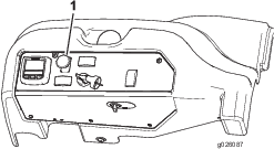
Position the PTO driveshaft under the front of the machine. Ensure that the slip-shaft yoke of the driveshaft is positioned toward the transmission driveshaft (Figure 4).
-
Align the spline and roll-pin hole of the driveshaft yoke with the transmission driveshaft.
-
Slide the PTO driveshaft end yoke onto the transmission driveshaft.
-
Secure the end yoke of the PTO driveshaft as follows:
-
Install the roll pin in the end yoke and shaft.
-
Install the bolts through the driveshaft end yoke.
-
Install and tighten the locknuts to secure the end yoke to the PTO driveshaft.
Note: Retain the remaining bolts, locknuts, and roll pin to secure the other end of the driveshaft to the attachment gearbox shaft.
-
Torque the locknuts to 20 to 25 N∙m (175 to 225 in-lb).
-
-
Lubricate the grease fittings on the PTO driveshaft.
-
After you connect the other end of the driveshaft to the attachment gearbox shaft, connect the wire-harness connector to the PTO solenoid-valve-coil connector (Figure 3).
Using the Optional Mower-Deck-Mounting Hardware
Parts needed for this procedure:
| Retainer pin | 2 |
| Grease fitting | 2 |
| Washer head screw (5/16 x 7/8 inch) | 2 |
Note: These components and procedure are required only if a mower deck that requires retainer pins is mounted to the traction unit. Refer to the mower deck Operator’s Manual for the installation instructions.
Note: If you are not installing a mower deck on the traction unit, remove or tie up the 4 deck-lift chains from the lift suspension.
Adjusting the Roll Bar
-
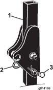
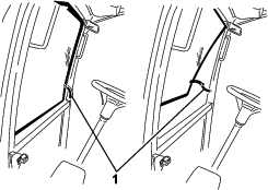
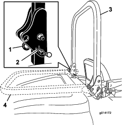
Remove the hairpin cotters and the pins from the roll bar (Figure 5).
-
Raise the roll bar to the upright position and install the 2 pins and secure them with the hairpin cotters (Figure 5).
Note: If you must lower the roll bar, push the bar forward to relieve pressure on the pins, remove the pins, lower the bar slowly, and secure it with the pins so that it does not damage the hood.
Checking the Tire Pressure
Check the tire pressure; refer to Checking the Tire Pressure.
Important: Maintain pressure in all tires to ensure a good quality-of-cut and proper machine performance. Do not underinflate the tires.
Checking the Fluid Levels
-
Check the hydraulic-fluid level before starting the engine, refer to Checking the Hydraulic System.
-
Check the engine-oil level before starting the engine, refer to Checking the Engine-Oil Level.
-
Check the cooling system before starting the engine; refer to Checking the Cooling System .
Product Overview
Become familiar with all the controls before you start the engine and operate the machine.
Traction Pedal
The traction pedal (Figure 6) controls the forward and reverse operation. Press the top of the pedal to move forward and the bottom to move rearward. The ground speed depends on how far you press the pedal. For no load, maximum ground speed, fully press the pedal while the throttle is in the FAST position.
To stop the machine, reduce the foot pressure on the traction pedal and allow it to return to the center position.
Brake Pedal
Use the brake pedal with the brake-pedal latch to engage and disengage the parking brake (Figure 6). To stop the machine, release the traction pedal and allow it to return to the center position. You can use the brake to assist in stopping the machine in an emergency situation.
Tilt-Steering Pedal
To tilt the steering wheel toward you, press the foot pedal down and pull the steering tower toward you to the most comfortable position and then release the pedal (Figure 6).
Parking Brake
To engage the parking brake, push down on the brake pedal and press the top forward to latch it (Figure 6). To disengage the parking brake, press the brake pedal until the parking-brake latch retracts.
Key Switch
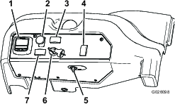
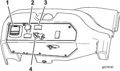
The key switch has 3 positions: OFF, ON/PREHEAT, and START (Figure 7).
Engine-Speed Switch
The engine-speed switch (Figure 7) has 2 modes to change the engine speed. By momentarily tapping the switch, you can increase or decrease the engine speed in increments of 100 rpm. Press and hold the switch to set the engine speed directly to high or low idle, depending on which end of the switch you press.
Power-Takeoff (PTO) Switch
The power-takeoff (PTO) switch starts and stops the attachment (Figure 7).
Power Point
The power point provides a 12 V power supply for electronic devices (Figure 7).
InfoCenter
The InfoCenter LCD display shows the operating status, various diagnostics, and other information about the machine (Figure 7).
Important: If the mower deck shuts down and the InfoCenter temperature-warning icon is on, push the PTO knob down; drive to a safe, flat area; move the throttle lever to the SLOW position; allow the traction pedal to move to the NEUTRAL position; and engage the parking brake. Allow the engine to idle for several minutes while it cools to a safe level. Shut off the engine and check the cooling system; refer to Checking the Cooling System .
Using the InfoCenter LCD Display
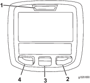
The InfoCenter LCD display shows information about your machine, such as the operating status, various diagnostics, and other information about the machine (Figure 8). There is a splash screen and main information screen of the InfoCenter. You can switch between the splash screen and main information screen at any time by pressing any of the InfoCenter buttons and then selecting the appropriate directional arrow.
-
Left button, menu access/back button—press this button to access the InfoCenter menus. You can use it to back out of any menu that you are currently using.
-
Middle button—use this button to scroll down menus.
-
Right button—use this button to open a menu where a right arrow indicates additional content.
Note: The purpose of each button may change depending on what is required at the time. Each button is labeled with an icon displaying its current function.
| SERVICE DUE | Indicates when scheduled service should be performed |
 | Engine rpm/status—indicates the engine rpm |
 | Hour meter |
 | Info icon |
 | Fast |
 | Slow |
 | Stationary regeneration required |
 | Glow plugs are active |
 | AC |
 | 2-wheel steer |
 | 4-wheel steer |
 | Operator must sit in seat |
 | Parking brake indicator—indicates when the parking brake is set |
 | Coolant Temperature-indicates the engine coolant temperature in either °C or °F |
 | Temperature (hot) |
 | PTO is engaged |
 | Denied or not allowed |
 | Engine start |
 | Stop or shutdown |
 | Engine |
 | Key switch |
 | PIN code |
 | CAN bus |
 | InfoCenter |
 | Bad or failed |
 | Bulb |
 | Output of TEC controller or control wire in harness |
 | Switch |
 | Operator must release switch |
 | Operator should change to indicated state |
| Symbols are often combined to form sentences. Some examples are shown below | |
 | Operator should put machine in Neutral |
 | Engine start denied |
 | Engine shutdown |
 | Engine coolant too hot |
 | DPF ash accumulation notification. Refer to Diesel Particulate Filter Regeneration for details. |
 | Sit down or engage parking brake |
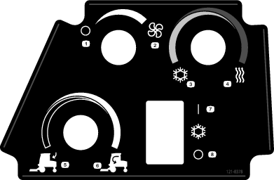
Cab Controls
Model with Cab Only
Air-Recirculation Control
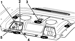
Sets the cab to either recirculate the air in the cabin or to draw air into the cabin from outside (Figure 9).
-
Set it to recirculate the air when using the air-conditioning.
-
Set it to draw air in when using the heater or fan.
Fan-Control Knob
Rotate the fan-control knob to regulate the speed of the fan (Figure 9).
Temperature-Control-Knob
Rotate the temperature-control knob to regulate the air temperature in the cab (Figure 9).
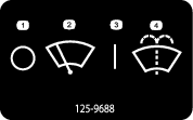
Windshield-Wiper Switch
Use this switch to turn the wind shield wipers on or off (Figure 9).
Air-Conditioning Switch
Use this switch to turn the air conditioning on or off (Figure 9).
Windshield Latch
Lift up the latch to open the windshield (Figure 10). Press in the latch to lock the windshield in the open position. Pull out and down on the latch to close and secure the windshield.
Rear Window Latch
Lift up the latches to open the rear window. Press in the latch to lock the window in the open position. Pull out and down on the latch to close and secure the window (Figure 10).
Important: You must close the rear window before opening the hood; otherwise, damage may occur.
Fuel Gauge
The fuel gauge (Figure 11) indicates the amount of fuel remaining in the fuel tank.
Steering Selector Switch
4-Wheel Drive Machines Only
Press the steering selector switch to the rear to engage 4-wheel steering and forward to return to 2-wheel steering (Figure 7).
Using the Menus
To access the InfoCenter menu system, press the menu access button while at the main screen. This brings you to the main menu. Refer to the following tables for a synopsis of the options available from the menus:
| Main Menu | |
| Menu Item | Description |
| Faults | The Faults menu contains a list of the recent machine faults. Refer to the Service Manual or your Authorized Toro Distributor for more information on the Faults menu and the information contained there. |
| Service | The Service menu contains information on the machine such as hours of use counters and other similar numbers. |
| Diagnostics | The Diagnostics menu displays the state of each machine switch, sensor and control output. You can use this to troubleshoot certain issues as it will quickly tell you which machine controls are on and which are off. |
| Settings | The Settings menu allows you to customize and modify configuration variables on the InfoCenter display. |
| About | The About menu lists the model number, serial number, and software version of your machine. |
| Service | |
| Menu Item | Description |
| Hours | Lists the total number of hours that the machine, engine, and PTO have been on, as well as the number of hours the machine has been transported and service due |
| Counts | Lists numerous counts the machine has experienced |
| Diagnostics | |
| Menu Item | Description |
| PTO | Indicates the inputs, qualifiers, and outputs for enabling the PTO circuit |
| Engine Run | Indicates the inputs, qualifiers, and outputs for starting the engine |
| Decks | Indicates the inputs, qualifiers, and outputs for lifting and lowering the deck |
| Steer Mode | Indicates the inputs, qualifiers, and outputs for switching between 2-wheel steer and 4-wheel steer |
| Machine Input | Indicates the state of other machine inputs such as accessories and A/C clutch |
| Settings | |
| Menu Item | Description |
| Units | Controls the units used on the InfoCenter; The menu choices are English or Metric. |
| Language | Controls the language used on the InfoCenter* |
| LCD Backlight | Controls the brightness of the LCD display |
| LCD Contrast | Controls the contrast of the LCD display |
| Protected Menus | Allows a person authorized by your company with the PIN code to access protected menus. |
| Auto Idle | Controls the amount of time allowed before returning the engine to low idle when the machine is stationary |
Only operator-faced text is translated. Faults, Service, and Diagnostics screens are service-faced. The titles are in the selected language, but the menu items are in English.
| About | |
| Menu Item | Description |
| Model | Lists the model number of the machine |
| SN | Lists the serial number of the machine |
| Machine Controller Revision | Lists the software revision of the master controller |
| InfoCenter Revision | Lists the software revision of the InfoCenter |
| CAN Bus | Lists the machine communication bus status |
Protected Menus
There are 2 operating configuration settings that are adjustable within the Settings Menu of the InfoCenter: Auto Idle time delay and Stationary Regeneration; refer to Diesel Particulate Filter Regeneration. You can lock these settings by using the Protected Menu.
Note: At the time of delivery, the initial password code is programmed by your distributor.
Accessing Protected Menus
Note: The factory default PIN code for you machine is either 0000 or 1234.If you changed the PIN code and forgot the code, contact your Authorized Toro Distributor for assistance.
-
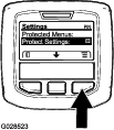
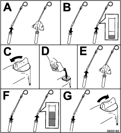
From the MAIN MENU, use the center button to scroll down to the SETTINGS MENU and press the right button (Figure 12).
-
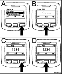
In the SETTINGS MENU, use the center button to scroll down to the PROTECTED MENU and press the right button (Figure 13A).
-
To enter the PIN code, press the center button until the correct first digit appears, then press the right button to move on to the next digit (Figure 13B and Figure 13C). Repeat this step until the last digit is entered and press the right button once more.
-
Press the middle button to enter the PIN code (Figure 13D).
Wait until the red indicator light of the InfoCenter illuminates.
Note: If the InfoCenter accepts the PIN code and the protected menu is unlocked, the word “PIN” displays in the upper right corner of the screen.
Note: Rotate the key switch to the OFF position and then to the ON position locks the protected menu.
You have the ability to view and change the settings in the Protected Menu. Once you access the Protected Menu, scroll down to Protect Settings option. Use the right button to change the setting. Setting the Protect Settings to OFF allows you to view and change the settings in the Protected Menu without entering the PIN code. Setting the Protect Settings to ON hides the protected options and requires you to enter the PIN code to change the setting in the Protected Menu. After you set the PIN code, rotate the key switch OFF and back to the ON position to enable and save this feature.
Setting the Auto Idle
-
In the Settings Menu, scroll down to Auto Idle.
-
Press the right button to change the auto idle time between OFF, 8S, 10S, 15S, 20S, and 30S.
Note: Specifications and design are subject to change without notice.
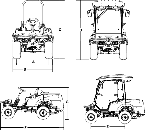
| Description | Figure 14 Reference | Dimension or Weight | |
| Height with roll bar up | C | 202 cm (80 inches) | |
| Height with roll bar down | G | 140 cm (55 inches) | |
| Height with cab | D | 225 cm (88-1/2 inches) | |
| Overall length | F | 276 cm (108-1/2 inches) | |
| Overall width | B | 138 cm (54 inches) | |
| Wheel base | E | 155 cm (61 inches) | |
| Wheel tread (tire center to center) rear | A | 112 cm (44 inches) | |
| Ground clearance | 15 cm (6 inches) | ||
| 4-Wheel Drive Machine with ROPS | Machine with Cab | 2-Wheel Drive Machine with ROPS | |
| No mower deck | 1,152 kg (2,540 lb) | 1,435 kg (3,163 lb) | 1,130 kg (2,492 lb) |
| 72 inch side discharge mower deck | 1,363 kg (3,004 lb) | 1,645 kg (3,627 lb) | 1,341 kg (2,956 lb) |
| 72 inch base mower deck | 1,341 kg (2,956 lb) | 1,623 kg (3,579 lb) | 1,319 kg (2,908 lb) |
| 62 inch base mower deck | 1,324 kg (2,918 lb) | 1,606 kg (3,541 lb) | 1,302 kg (2,870 lb) |
| 100 inch rear discharge mower deck | 1,510 kg (3,330 lb) | 1,793 kg (3,953 lb) | 1,489 kg (3,282 lb) |
Attachments/Accessories
A selection of Toro approved attachments and accessories is available for use with the machine to enhance and expand its capabilities. Contact your Authorized Service Dealer or Distributor or go to www.Toro.com for a list of all approved attachments and accessories.
To best protect your investment and maintain optimal performance of your Toro equipment, count on Toro genuine parts. When it comes to reliability, Toro delivers replacement parts designed to the exact engineering specification of our equipment. For peace of mind, insist on Toro genuine parts.
Operation
Note: Determine the left and right sides of the machine from the normal operating position.
Before Operation
Before Operation Safety
General Safety
-
Never allow children or untrained people to operate or service the machine. Local regulations may restrict the age of the operator. The owner is responsible for training all operators and mechanics.
-
Become familiar with the safe operation of the equipment, operator controls, and safety signs.
-
Know how to stop the machine and shut off the engine quickly.
-
Check that operator-presence controls, safety switches, and shields are attached and functioning properly. Do not operate the machine unless they are functioning properly.
-
Before mowing, always inspect the machine to ensure that the blades, blade bolts, and cutting assemblies are in good working condition. Replace worn or damaged blades and bolts in sets to preserve balance.
-
Inspect the area where you will use the machine and remove all objects that the machine could throw.
Fuel Safety
-
Use extreme care in handling fuel. It is flammable and its vapors are explosive.
-
Extinguish all cigarettes, cigars, pipes, and other sources of ignition.
-
Use only an approved fuel container.
-
Do not remove the fuel cap or fill the fuel tank while the engine is running or hot.
-
Do not add or drain fuel in an enclosed space.
-
Do not store the machine or fuel container where there is an open flame, spark, or pilot light, such as on a water heater or other appliance.
-
If you spill fuel, do not attempt to start the engine; avoid creating any source of ignition until the fuel vapors have dissipated.
Adding Fuel
Fuel Specification
Important: Use only ultra-low sulphur diesel fuel. Fuel with higher rates of sulfur degrades the diesel oxidation catalyst (DOC), which causes operational problems and shortens the service life of engine components.Failure to observe the following cautions may damage the engine.
-
Never use kerosene or gasoline instead of diesel fuel.
-
Never mix kerosene or used engine oil with the diesel fuel.
-
Never keep fuel in containers with zinc plating on the inside.
-
Do not use fuel additives.
Petroleum Diesel
Cetane rating: 45 or higher
Sulfur content: Ultra-low sulfur (<15 ppm)
| Diesel fuel specification | Location |
| ASTM D975 | USA |
| No. 1-D S15 | |
| No. 2-D S15 | |
| EN 590 | European Union |
| ISO 8217 DMX | International |
| JIS K2204 Grade No. 2 | Japan |
| KSM-2610 | Korea |
-
Use only clean, fresh diesel fuel or biodiesel fuels.
-
Purchase fuel in quantities that can be used within 180 days to ensure fuel freshness.
Use summer-grade diesel fuel (No. 2-D) at temperatures above -7°C (20°F) and winter-grade fuel (No. 1-D or No. 1-D/2-D blend) below that temperature.
Note: Use of winter-grade fuel at lower temperatures provides lower flash point and cold flow characteristics which eases starting and reduces fuel filter plugging.Using summer-grade fuel above -7°C (20°F) contributes toward longer fuel pump life and increased power compared to winter-grade fuel.
Biodiesel
This machine can also use a biodiesel blended fuel of up to B20 (20% biodiesel, 80% petroleum diesel).
Sulfur content: Ultra-low sulfur (<15 ppm)
Biodiesel fuel specification: ASTM D6751 or EN14214
Blended fuel specification: ASTM D975, EN590, or JIS K2204
Important: The petroleum diesel portion must be ultra-low sulfur.
Observe the following precautions:
-
Biodiesel blends may damage painted surfaces.
-
Use B5 (biodiesel content of 5%) or lesser blends in cold weather.
-
Monitor seals, hoses, gaskets in contact with fuel as they may be degraded over time.
-
Fuel filter plugging may be expected for a time after converting to biodiesel blends.
-
Contact your Authorized Toro Distributor if you wish for more information on biodiesel.
Fuel Tank Capacity
51 L (13.5 US gallons)
Filling the Fuel Tank
Note: If possible, fill the fuel tank after each use. This minimizes possible buildup of condensation inside the fuel tank.
Add fuel to the fuel tank until the level is even with the bottom of the filler neck. Do not overfill the fuel tank.
Checking the Engine-Oil Level
Before you start the engine and use the machine, check the oil level in the engine crankcase; refer to Checking the Engine-Oil Level.
Checking the Cooling System
Before you start the engine and use the machine, check the cooling system; refer to Checking the Cooling System.
Checking the Hydraulic System
Before you start the engine and use the machine, check the hydraulic system; refer to Checking the Hydraulic System.
Using the Safety-Interlock System
Caution
If the safety-interlock switches are disconnected or damaged the machine could operate unexpectedly and cause personal injury.
-
Do not tamper with the interlock switches.
-
Check the operation of the interlock switches daily and replace any damaged switches before operating the machine.
Understanding the Safety-Interlock System
The safety-interlock system is designed to prevent the engine from starting unless the following occurs:
-
You are sitting on the seat or the parking brake is engaged.
-
The power takeoff (PTO) is disengaged.
-
The traction pedal is in the NEUTRAL position.
-
The engine temperature is below the maximum operating temperature.
The safety-interlock system also is designed to shut off the engine when the traction pedal moves from the NEUTRAL position with the parking brake engaged. If you rise from the seat when the PTO is engaged, there is a 1-second delay and then the engine shuts off.
Testing the Safety-Interlock System
Test the safety interlock system before you use the machine each time. If the safety system does not operate as described below, have an Authorized Service Dealer repair the safety system immediately.
-
Sitting on the seat, engage the parking brake and move the PTO to the ON position. Try starting the engine; the engine should not start.
-
Sitting on the seat, engage the parking brake and move the PTO to the OFF position. Press the traction pedal. Try starting the engine; the engine should not start.
-
Sitting on the seat, engage the parking brake, move the PTO switch to the OFF position, and allow the traction pedal to return to the NEUTRAL position. Now start the engine. While the engine is running, disengage the parking brake, engage the PTO and rise slightly from the seat. On 2-wheel-drive machines, the engine should stop within 2 seconds. On 4-wheel-drive machines, the mower deck shuts off and the engine continues to run.
-
Without sitting on the seat, engage the parking brake, move the PTO switch to the OFF position, and move the traction pedal to the NEUTRAL position. Now start the engine. While the engine is running, press the traction pedal; the engine should shut off within 2 seconds.
-
Without an operator on the seat, disengage the parking brake, move the PTO switch to off, and allow the traction pedal to return to the NEUTRAL position. Try starting the engine; the engine should not start.
Positioning the Standard Seat
Changing the Seat Position
The seat can move forward and backward. Position the seat where you have the best control of the machine and are most comfortable.
-
To adjust the seat, move the lever sideways to unlock the seat (Figure 16).
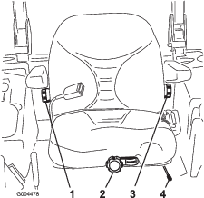
-
Slide the seat to the desired position and release the lever to lock the seat in position.
-
Verify that the seat has locked into place by attempting to move it back and forth.
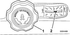
Changing the Seat Suspension
You can adjust the seat to provide a smooth and comfortable ride. Position the seat where you are most comfortable.
Without sitting on the seat, turn the knob in front in either direction to provide the best comfort (Figure 16).
Changing the Back Position
You can adjust the back of the seat to provide a comfortable ride. Position the back of the seat where it is most comfortable.
To adjust the back of the seat, turn the knob, located under the right-side armrest, in either direction to provide the best comfort (Figure 16).
Changing the Lumbar Support
You can adjust the back of the seat to provide a customized lumbar support for your lower back.
To adjust the back of the seat, turn the knob, under the left-side armrest, in either direction to provide the best comfort (Figure 16).
Raising and Lowering the Seat
To access the hydraulic and other systems under the seat, you must unlatch the seat and swing it forward.
-
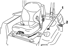
Move the seat latch, located on the left side of the seat, rearward to unlatch the seat and pull forward on the top of the seat (Figure 18).
-
To lower the seat, pull up the seat-latch-release bar and lower the seat into the locked position.
During Operation
During Operation Safety
General Safety
-
The owner/operator can prevent and is responsible for accidents that may cause personal injury or property damage.
-
Wear appropriate clothing, including eye protection; slip-resistant, substantial shoes; and hearing protection. Tie back long hair and do not wear loose jewelry.
-
Do not operate the machine while ill, tired, or under the influence of alcohol or drugs.
-
Never carry passengers on the machine and keep bystanders and pets away from the machine during operation.
-
Operate the machine only in good visibility to avoid holes or hidden hazards.
-
Avoid mowing on wet grass. Reduced traction could cause the machine to slide.
-
Before you start the engine, ensure that all drives are in neutral, the parking brake is engaged, and you are in the operating position.
-
Keep your hands and feet away from rotating parts. Keep clear of the discharge opening at all times.
-
Look behind and down before backing up to be sure of a clear path.
-
Use care when approaching blind corners, shrubs, trees, or other objects that may obscure your vision.
-
Do not mow near drop-offs, ditches, or embankments. The machine could suddenly roll over if a wheel goes over the edge or if the edge gives way.
-
Stop the blades whenever you are not mowing.
-
Stop the machine, remove the key, and wait for all moving parts to stop before inspecting the attachment after striking an object or if there is an abnormal vibration in the machine. Make all necessary repairs before resuming operation.
-
Slow down and use caution when making turns and crossing roads and sidewalks with the machine. Always yield the right-of-way.
-
Disengage the drive to the cutting unit and shut off the engine before adjusting the height of cut (unless you can adjust it from the operating position).
-
Never run an engine in an area where exhaust gasses are enclosed.
-
Never leave a running machine unattended.
-
Before leaving the operating position (including to empty the catchers or to unclog the chute), do the following:
-
Park the machine on level ground.
-
Disengage the power takeoff and lower the attachments.
-
Engage the parking brake.
-
Shut off the engine and remove the key.
-
Wait for all moving parts to stop.
-
-
Do not operate the machine when there is the risk of lightning.
-
Do not use the machine as a towing vehicle.
-
Use accessories, attachments, and replacement parts approved by The Toro® Company only.
Rollover Protection System (ROPS) Safety
-
Do not remove the ROPS from the machine.
-
Ensure that the seat belt is attached and that you can release it quickly in an emergency.
-
Check carefully for overhead obstructions and do not contact them.
-
Keep the ROPS in safe operating condition by thoroughly inspecting it periodically for damage and keeping all the mounting fasteners tight.
-
Replace a damaged ROPS components. Do not repair or alter them.
Machines with Cabs
-
The ROPS is an integral and effective safety device.
-
A cab installed by Toro is a roll bar.
-
Always wear your seat belt.
Machines with a Foldable Roll Bar
-
Always use the seat belt with the roll bar in the raised position.
-
The ROPS is an integral safety device. Keep a folding roll bar in the raised and locked position, and use the seat belt when operating the machine with the roll bar in the raised position.
-
Lower a folding roll bar temporarily only when necessary. Do not wear the seat belt when the roll bar is folded down.
-
Be aware that there is no rollover protection when a folded roll bar is in the down position.
-
Check the area that you will be mowing and never fold down a folding roll bar in areas where there are slopes, drop-offs, or water.
Slope Safety
Slopes are a major factor related to loss of control and rollover accidents, which can result in severe injury or death. You are responsible for safe slope operation. Operating the machine on any slope requires extra caution.
-
Evaluate the site conditions to determine if the slope is safe for machine operation including surveying the site. Always use common sense and good judgment when performing this survey.
-
Review the slope instructions listed below for operating the machine on slopes and review the conditions in which you would operate the machine to determine whether you can operate it in the conditions on that day and at that site. Changes in the terrain can result in a change in slope operation for the machine.
-
Avoid starting, stopping, or turning the machine on slopes. Avoid making sudden changes in speed or direction. Make turns slowly and gradually.
-
Do not operate a machine under any conditions where traction, steering, or stability is in question.
-
Remove or mark obstructions such as ditches, holes, ruts, bumps, rocks, or other hidden hazards. Tall grass can hide obstructions. Uneven terrain could overturn the machine.
-
Be aware that operating the machine on wet grass, across slopes, or downhill may cause the machine to lose traction. Loss of traction to the drive wheels may result in sliding and a loss of braking and steering.
-
Use extreme caution when operating the machine near drop-offs, ditches, embankments, water hazards, or other hazards. The machine could suddenly roll over if a wheel goes over the edge or the edge caves in. Establish a safety area between the machine and any hazard.
-
Identify hazards at the base of the slope. If there are hazards, mow the slope with a pedestrian-controlled machine.
-
If possible, keep the cutting unit(s) lowered to the ground while operating on slopes. Raising the cutting unit(s) while operating on slopes can cause the machine to become unstable.
-
Use extreme caution while operating the machine with grass-collection systems or other attachments. These can change the stability of the machine and cause a loss of control.
-
Always keep the machine in gear when going down slopes. Do not coast downhill (applicable only to gear drive units).
Using the Rollover-Protection System (ROPS)
-
Keep the roll bar in the raised and locked position and use the seat belt when operating the machine.
-
Ensure that you can release the seat belt quickly in an emergency situation.
-
Check the area that you will mow and never fold the roll bar in areas where there are slopes, drop-offs, or water.
Warning
To avoid injury or death from rollover, keep the roll bar in the raised locked position and use the seat belt.
Ensure that the seat plate is secured with the seat latch.
Warning
You have no rollover protection when the roll bar is in the down position.
-
Lower the roll bar only when necessary.
-
Do not wear the seat belt when the roll bar is in the down position.
-
Drive slowly and carefully.
-
Raise the roll bar as soon as clearance permits.
-
Check carefully for overhead clearances (i.e., branches, doorways, electrical wires) before driving under any objects and do not contact them.
-
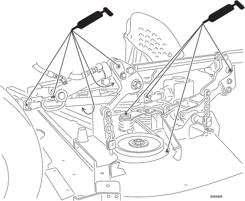
To lower the roll bar, remove the hairpin cotters, push the roll bar forward against the springs, and remove the 2 pins (Figure 20).
-
Lower the roll bar to the down position (Figure 20).
-
Install the 2 pins and secure them with the hairpin cotters (Figure 20).
Important: Ensure that the seat is secured with the seat latch.
-
To raise the roll bar, remove the hairpin cotter pins and remove the 2 pins (Figure 20).
-
Raise the roll bar to the upright position and install the 2 pins and secure them with the hairpin cotters (Figure 20).
Important: Always use the seat belt when the roll bar is in the raised and locked position. Do not use the seat belt when the roll bar is in the lowered position.
Starting and Shutting Off the Engine
Starting the Engine
-
Park the machine on a level surface.
-
Raise the roll bar up and lock it into place, sit on the seat, and fasten the seat belt.
-
Make sure that the traction pedal is in the NEUTRAL position.
-
Engage the parking brake.
-
Move the power-takeoff (PTO) switch to the OFF position (Figure 21).
-
Turn the key clockwise to the RUN position.
Note: The InfoCenter glow-plug icon turns on in 6 seconds.
-
After the InfoCenter glow-plug icon goes out, turn the key to the START position. When the engine starts, release the key.
Important: Use starting cycles of no more than 15 seconds per minute to avoid overheating the starter motor.
Note: Additional starting cycles may be required when starting the engine for the first time after the fuel system has been completely drained.
Important: When you start the engine for the first time, or after an engine oil change or an overhaul of the engine, the transmission, or a wheel motor, operate the machine with the engine-speed switch in the Slow position in both the forward and reverse directions for 1 to 2 minutes. Also operate the deck lift switch and the PTO switch to ensure proper operation of all the parts. Then shut the engine off and check the fluid levels and check for oil leaks, loose parts, and any other noticeable malfunctions.
Shutting Off the Engine
-
Park the machine on a level surface.
-
Disengage the PTO, make sure that the traction pedal is in the NEUTRAL position, engage the parking brake, and move the engine-speed switch to the idle position.
-
Let the engine idle for 60 seconds.
-
Turn the key to the OFF position.
-
Remove the key to prevent the engine from accidentally starting and before you transport or store the machine.
Note: Remove the key; otherwise, the fuel pump or accessories may run and cause the battery to lose charge.
Caution
Children or bystanders may be injured if they move or attempt to operate the machine while it is unattended.
Always remove the key and engage the parking brake when leaving the machine unattended, even for a short period of time between operation.
Driving the Machine
The throttle control regulates the engine speed as measured in rpm (revolutions per minute). Place the throttle control in the FAST position for best performance. Always operate the throttle in the FAST position when mowing.
Stopping the Machine
To stop the machine, release the traction pedal to the NEUTRAL position.
Engage the parking brake whenever you leave the machine and remove the key.
Selecting the Steering Mode
For maximum trimming and minimum turf damage, operate the machine in the 4-wheel-steering mode. However, when transporting the machine on roads or trails, switch the machine into 2-wheel-steering mode.
Switching from 4-Wheel Steering to 2-Wheel Steering
Press the steering-selector switch (Figure 22) to the forward position. When the wheels are not aligned in the forward position, the green light flashes and the machine remains in the 4-wheel-steering mode until the 4 tires point straight ahead. Turn the steering wheel slowly to straighten out the wheels until the green light stops flashing and remains on. When the switch light is solid green, the machine is in 2-wheel steering.
Note: If you turn the steering wheel too briskly, steering misalignment may occur.
Switching from 2-Wheel Steering to 4-Wheel Steering
Press the steering-selector switch (Figure 22) to the rearward position. When the front wheels are not aligned in the forward position, the green light flashes and the machine remains in 2-wheel-steering mode until the 4 tires point straight ahead. Turn the steering wheel slowly to straighten out the wheels until the green light stops flashing and remains off. When the switch light is continuously off, the machine is in the 4-wheel-steering mode.
Note: If you turn the steering wheel too briskly, steering misalignment may occur.
Note: If the steering system is misaligned after repeated 2-wheel-steering to 4-wheel-steering engagements, refer to Correcting Steering Misalignment.
Operating the Mower Deck or Attachment
Raising and Lowering the Mower/Attachment
The deck-lift switch raises and lowers the mower deck/attachment (Figure 23). The engine must be running for you to use this switch.
-
To lower the mower deck/attachment, push the switch forward.
-
To raise the mover deck/attachment, push the switch rearward.
Important: Do not continue to hold the switch back after the mower/attachment is fully raised. Doing so causes damage the hydraulic system.
Note: To lock the mower deck/attachment in the raised position, raise the deck/attachment past the 15 cm (6 inch) position, remove the height-of-cut stop pin, and insert the pin into the 15 cm (6 inch) height-of-cut position; refer to Adjusting the Height of Cut.
Engaging the Power Takeoff (PTO)
The power-takeoff (PTO) switch starts and stops the mower blades and some powered attachments.
-
If the engine is cold, allow the engine to warm up 5 to 10 minutes before engaging the PTO.
-
While seated in the seat, ensure that the traction pedal is in the NEUTRAL position and that the engine is at full throttle.
-
Pull up the PTO switch to engage it (Figure 24).
Disengaging the PTO
To disengage, push the PTO switch to the OFF position.
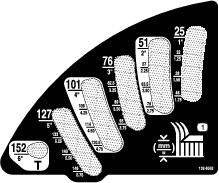
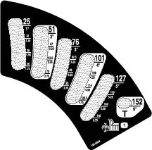
Adjusting the Height of Cut
You can adjust the height of cut from 2.5 to 15.8 cm (1 to 6 inches) in 6 mm (1/4 inch) increments by relocating the height-of-cut pin into different hole locations.
-
With the engine running, push back the deck-lift switch until the mower deck is fully raised, and release the switch immediately as shown in Figure 25.
-
Rotate the height-of-cut pin until the nub on it lines up with the slots in the holes in the height-of-cut bracket and remove it (Figure 25).
-
Select a hole in the height-of-cut bracket corresponding to the desired height of cut, insert the pin, and rotate it down to lock it in place (Figure 25).
Note: There are 4 rows of hole positions (Figure 25). The top row gives you the height of cut listed above the pin. The second row down gives you the height listed plus 6 mm (1/4 inch). The third row down gives you the height listed plus 12 mm (1/2 inch). The bottom row gives you the height listed plus 18 mm (3/4 inch). For the 15.8 cm (6 inches) position, there is only 1 hole, located in the second row. This does not add 6 mm (1/4 inch) to the 15.8 cm (6 inches) position.
-
Adjust the anti-scalp rollers and skids as required.
Cutting Grass with the Machine
Note: Cutting grass at a rate that loads the engine promotes DPF regeneration.
-
Move the machine to the job site.
-
Whenever possible, set the engine-speed switch to high idle.
-
Engage the PTO switch.
-
Gradually move the traction pedal forward and slowly drive the machine over the mowing area.
-
Once the front of the cutting units are over the mowing area, lower the cutting units.
-
Cut grass so that the blades can cut and discharge clippings at a high rate while producing a good quality of cut.
Note: If the cutting rate is too high, the quality of cut may deteriorate. Reduce the ground speed of the machine or reduce the width of cut to regain high idle engine speed.
-
When the cutting units are over the far edge of the mowing area, lift the cutting units.
-
Perform a tear-shaped turn to quickly line up for your next pass.
Diesel Particulate Filter Regeneration
The diesel particulate filter (DPF) is part of the exhaust system. The diesel-oxidation catalyst of the DPF reduces harmful gasses and the soot filter removes soot from the engine exhaust.
The DPF regeneration process uses heat from the engine exhaust to incinerate the soot accumulated on the soot filter, converting the soot to ash, and clears the channels of the soot filter so that filtered engine exhaust flows out the DPF.
The engine computer monitors the accumulation of soot by measuring the back pressure in the DPF. If the back pressure is too high, soot is not incinerating in the soot filter through normal engine operation. To keep the DPF clear of soot, remember the following:
-
Passive regeneration occurs continuously while the engine is running—run the engine at full engine speed when possible to promote DPF regeneration.
-
If the back pressure in the DPF is too high or a reset regeneration has not occurred for 100 hours, the engine computer signals you through the InfoCenter when reset regeneration is running.
-
Allow the reset regeneration process to complete before shutting off the engine.
Operate and maintain your machine with the function of the DPF in mind. Engine load at high idle (full throttle) engine speed generally produces adequate exhaust temperature for DPF regeneration.
Important: Minimize the amount of time that you idle the engine or operate the engine at low-engine speed to help reduce the accumulation of soot in the soot filter.
DPF Soot Accumulation
-
Over time, the diesel particulate filter accumulates soot in the soot filter. The computer for the engine monitors the soot level in the DPF.
-
When enough soot accumulates, the computer informs you that it is time to regenerate the DPF.
-
DPF regeneration is a process that heats the DPF to convert the soot to ash.
-
In addition to the warning messages, the computer reduces the power produced by the engine at different soot-accumulation levels.
| Indication Level | Fault Code | Engine Power Rating | Recommended Action |
| Level 1: Engine Warning |
 | The computer de-rates the engine power to 85%. | Perform a parked regeneration as soon as possible; refer to Parked or Recovery Regeneration. |
| Level 2: Engine Warning |
 | The computer de-rates the engine power to 50%. | Perform a recovery regeneration as soon as possible; refer to Parked or Recovery Regeneration. |
DPF Ash Accumulation
-
The lighter ash is discharged through the exhaust system; the heavier ash collects in the soot filter.
-
Ash is a residue of the regeneration process. Over time, the diesel particulate filter accumulates ash that does not discharge with the engine exhaust.
-
The computer for the engine calculates the amount of ash accumulated in the DPF.
-
When enough ash accumulates, the engine computer sends information to the InfoCenter in the form of an engine fault to indicate the accumulation of ash in the DPF.
-
The fault messages indicate that it is time to service the DPF.
-
In addition to the warnings, the computer reduces the power produced by the engine at different ash-accumulation levels.
| Indication Level | Fault Code | Engine Speed Reduction | Engine Power Rating | Recommended Action |
|---|---|---|---|---|
| Level 1: Engine Warning |
 | None | The computer de-rates the engine power to 85%. | Service the DPF; refer to Servicing the Diesel-Oxidation Catalyst (DOC) and the Soot Filter |
| Level 2: Engine Warning |
| None | The computer de-rates the engine power to 50%. | Service the DPF; refer to Servicing the Diesel-Oxidation Catalyst (DOC) and the Soot Filter |
| Level 3: Engine Warning |
 | Engine speed at maximum torque + 200 rpm | The computer de-rates the engine power to 50%. | Service the DPF; refer to Servicing the Diesel-Oxidation Catalyst (DOC) and the Soot Filter |
Types of Diesel Particulate Filter Regeneration
| Type of Regeneration | Conditions that cause DPF regeneration | DPF description of operation |
|---|---|---|
| Passive | Occurs during normal operation of the machine at high-engine speed or high-engine load | • The InfoCenter does not display an icon indicating passive regeneration. |
| • During passive regeneration, the DPF processes high-heat exhaust gasses, oxidizing harmful emissions, and burning soot to ash. | ||
| Refer to Passive DPF Regeneration. | ||
| Assist | Occurs because of low-engine speed, low-engine load, or after the computer detects the DPF is becoming obstructed with soot | • The InfoCenter does not display an icon indicating assist regeneration. |
| • During assist regeneration, the engine computer adjusts the engine settings to raise the exhaust temperature. | ||
| Refer to Assist DPF Regeneration. | ||
| Reset | Occurs every 100 hours | • When the high exhaust-temperature icon  is displayed in the InfoCenter,
a regeneration is in progress. is displayed in the InfoCenter,
a regeneration is in progress. |
| Also occurs after assist regeneration only if the computer detects that assist regeneration did not sufficiently reduce the soot level | ||
| • During reset regeneration, the engine computer adjusts the engine settings to raise the exhaust temperature. | ||
| Refer to Reset Regeneration. |
| Type of Regeneration | Conditions that cause DPF regeneration | DPF description of operation |
|---|---|---|
| Parked | Occurs because the computer detects back pressure in the DPF due to soot buildup | • When the reset-standby/parked
or recovery regeneration icon  or ADVISORY #188 displays
in the InfoCenter, a regeneration is requested. or ADVISORY #188 displays
in the InfoCenter, a regeneration is requested. |
| Also occurs because the operator initiates a parked regeneration | ||
| May occur because you set the InfoCenter to inhibit reset regeneration and continued operating the machine, adding more soot when the DPF already needs a reset regeneration | • Perform the parked regeneration as soon as possible to avoid needing a recovery regeneration. | |
| May result from using the incorrect fuel or engine oil | • A parked regeneration requires 30 to 60 minutes to complete. | |
| • You must have at least a 1/4 tank of fuel in the tank. | ||
| • You must park the machine to perform a parked regeneration. | ||
| Refer to Parked or Recovery Regeneration. | ||
| Recovery | Occurs because the operator ignored requests for a parked regeneration and continued operating the machine, adding more soot to the DPF | • When the reset-standby/parked or recovery
regeneration icon or ADVISORY #190 displays
in the InfoCenter, a recovery regeneration is requested. |
| • A recovery regeneration requires up to 3 hours to complete. | ||
| • You must have at least a 1/2 tank of fuel in the machine. | ||
| • You must park the machine to perform a recovery regeneration. | ||
| Refer to Parked or Recovery Regeneration. |
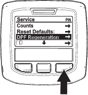
Accessing the DPF Regeneration Menus
Accessing the DPF Regeneration Menus
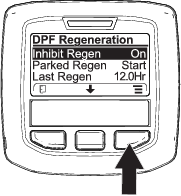
Time Since Last Regeneration
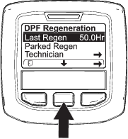
Access the DPF Regeneration menu, press the center button to scroll down to the LAST REGEN field (Figure 32).
Use the LAST REGEN field to determine how many hours you have run the engine since the last reset, parked, or recovery regeneration.
Technician Menu
Important: For operating convenience, you may decide to perform a parked regeneration before the soot load reaches 100%, provided the engine has run more than 50 hours since the last successful reset, parked, or recovery regeneration.
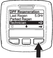
Use the technician menu to view the current state of engine regeneration control and view the reported soot level.
Access the DPF Regeneration menu, press the center button to scroll down to the TECHNICIAN option, and press the right button to select the Technician entry (Figure 33).
-
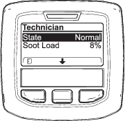
Use the DPF operation table to understand the current state of DPF operation (Figure 34).
.
DPF Operation Table
State Description Normal The DPF is in normal-operating mode—passive regeneration. Assist Regen The engine computer is performing an assist regeneration. Reset Stby The engine computer is trying to run a reset regeneration, but 1 of the following conditions prevents regeneration: The regen inhibit setting is set to ON. The exhaust temperature is too low for regeneration. Reset Regen The engine computer is running a reset regeneration. Parked Stby The engine computer is requesting that you run a parked regeneration. Parked Regen You initiated a parked regeneration request and the engine computer is processing the regeneration. Recov. Stby The engine computer is requesting that you run a recovery regeneration. Recov. Regen You initiated a recovery regeneration request and the engine computer is processing the regeneration. -
View the soot load which is measured as the percentage of soot in the DPF(Figure 35); refer to the soot-load table.
Note: The soot load value varies as the machine is operated and DPF regeneration occurs.

Soot-Load Table
Important Soot Load Values Regeneration State 0% to 5% Minimum soot load range 78% The engine computer performs an assist regeneration. 100% The engine computer automatically requests a parked regeneration. 122% The engine computer automatically requests a recovery regeneration.
Passive DPF Regeneration
-
Passive regeneration occurs as part of normal engine operation.
-
While operating the machine, run the engine at full-engine speed and high load when possible to promote DPF regeneration.
Assist DPF Regeneration
-
The engine computer adjusts engine settings to raise the exhaust temperature.
-
While operating the machine, run the engine at full engine speed and high load when possible to promote DPF regeneration.
Reset Regeneration
Caution
The exhaust temperature is hot (approximately 600°C (1,112°F) during DPF regeneration. Hot exhaust gas can harm you or other people.
-
Never operate the engine in an enclosed area.
-
Make sure that there are no flammable materials around the exhaust system.
-
Never touch a hot exhaust system component.
-
Never stand near or around the exhaust pipe of the machine.
-
The high exhaust-temperature icon
displays in the InfoCenter
(Figure 36). -
The engine computer adjusts engine settings to raise the exhaust temperature.
Important: The high exhaust-temperature icon indicates that the exhaust temperature discharged from of your machine may be hotter than during regular operation.
-
While operating the machine, run the engine at full engine speed and high load when possible to promote DPF regeneration.
-
The icon displays in the InfoCenter while the reset regeneration is processing.
-
Whenever possible, do not shut off the engine or reduce engine speed while the reset regeneration is processing.
Important: Whenever possible, allow the machine to complete the reset regeneration process before shutting off the engine.
Periodic Reset Regeneration
If the engine has not completed a successful Reset, Parked, or Recovery regeneration in the previous 100 hours of engine operation, the engine computer will attempt to perform a reset regeneration.
Setting the Inhibit Regen
Reset Regeneration Only

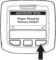
Note: If you set the InfoCenter to inhibit regeneration, the InfoCenter displays ADVISORY #185 (Figure 37) every 15 minutes while the engine requests a reset regeneration.
A reset regeneration produces the elevated engine exhaust. If you are operating the machine around trees, brush, tall grass, or other temperature-sensitive plants or materials, you can use the Inhibit Regen setting to prevent the engine computer from performing a reset regeneration.
Important: When you shut off the engine and start it again, the inhibit regen setting defaults to OFF.

Allowing a Reset Regeneration
The InfoCenter displays the high exhaust-temperature icon when the reset regeneration
is in process.
Note: If INHIBIT REGEN is set to ON, the InfoCenter displays ADVISORY #185 (Figure 40). Press button 3 to set inhibit regeneration setting to OFF and continue with the reset regeneration.
Note: If the engine exhaust temperature is too low, the InfoCenter displays ADVISORY #186 (Figure 41) to inform you to set the engine to full throttle (high idle).

Note: When the reset regeneration completes, the high exhaust-temperature disappears from the InfoCenter
screen.
Parked or Recovery Regeneration
-
When the engine computer requests either a parked regeneration or a recovery regeneration, the regeneration request icon (Figure 42) displays in the InfoCenter.
-
The machine does not automatically perform a parked regeneration or a recovery regeneration, you must run the regeneration through the InfoCenter.
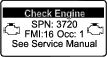
Parked Regeneration Messages
When a parked regeneration is requested by the engine computer the following messages display in the InfoCenter:
-
Engine warning SPN 3720, FMI 16 (Figure 43)
-
Parked regeneration required ADVISORY #188 (Figure 44)
Note: Advisory #188 displays every 15 minutes.

-
If you do not perform a parked regeneration within 2 hours, the InfoCenter displays parked regeneration required—power takeoff disabled ADVISORY #189 (Figure 45).
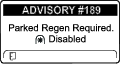
Important: Perform a parked regeneration to restore the PTO function; refer to Preparing to Perform a Parked or Recovery Regeneration and Performing a Parked or Recovery Regeneration.
Note: The Home screen displays the PTO disabled Icon (Figure 46).
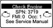
Recovery Regeneration Messages
When a recovery regeneration is requested by the engine computer, the following messages display in the InfoCenter:
-
Engine warning SPN 3719, FMI 0 (Figure 47)
-
Recovery regeneration required—power takeoff disabled ADVISORY #190 (Figure 48)
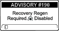
Important: Perform a recovery regeneration to restore the PTO function; refer to Preparing to Perform a Parked or Recovery Regeneration and Performing a Parked or Recovery Regeneration.
Note: The Home screen displays the PTO disabled Icon; refer to Figure 46 in Parked Regeneration Messages.
DPF Status-Limitation
-
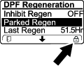
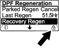
If the engine computer requests a recovery regeneration or is processing a recovery regeneration and you scroll down to the PARKED REGEN option, parked regeneration locks and the lock icon (Figure 49) appears in the lower right corner of the InfoCenter.
-
If the engine computer has not requested a recovery regeneration and you scroll down to the RECOVERY REGEN option, the recovery regeneration locks and the lock icon (Figure 50) appears in the lower right corner of the InfoCenter.
Preparing to Perform a Parked or Recovery Regeneration
-
Ensure that the machine has fuel in the tank for the type of regeneration you are performing:
-
Parked Regeneration: Ensure that you have 1/4 tank of fuel before performing the parked regeneration.
-
Recovery Regeneration: Ensure that you have 1/2 tank of fuel before performing the recovery regeneration.
-
-
Move the machine outside to an area away from combustible materials.
-
Park the machine on a level surface.
-
Ensure that the traction control or motion-control levers are in the NEUTRAL position.
-
If applicable, shut off the PTO, and lower the cutting units or accessories.
-
Engage the parking brake.
-
Set the throttle to the low IDLE position.
Performing a Parked or Recovery Regeneration
Caution
The exhaust temperature is hot (approximately 600°C (1,112°F) during DPF regeneration. Hot exhaust gas can harm you or other people.
-
Never operate the engine in an enclosed area.
-
Make sure that there are no flammable materials around the exhaust system.
-
Never touch a hot exhaust system component.
-
Never stand near or around the exhaust pipe of the machine.
Important: The computer of the machine cancels DPF regeneration if you increase the engine speed from low idle or release the parking brake.
-
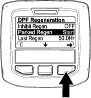
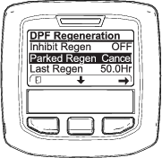
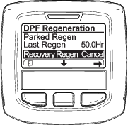
Access the DPF Regeneration menu, press the center button to scroll down to either the PARKED REGEN START option or the RECOVERY REGEN START option (Figure 51), and press the right button to select the start the regeneration (Figure 51).

-
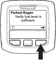
At the VERIFY FUEL LEVEL screen, verify that you have 1/4 tank of fuel if you are performing the parked regeneration or 1/2 tank of fuel if you are performing the recovery regeneration, and press the right button to continue (Figure 52).

-
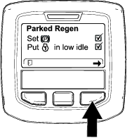
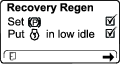
At the DPF checklist screen, verify that the parking brake is engaged and that the engine speed is set to low idle (Figure 53).
-
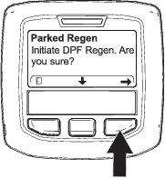
At the INITIATE DPF REGEN screen, press the right button to continue (Figure 54).

-
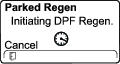
The InfoCenter displays the INITIATING DPF REGEN message (Figure 55).

-
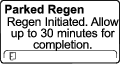
The InfoCenter displays the time to complete message (Figure 56).
-
The engine computer checks the engine state and fault information. The InfoCenter may display the following messages found in the table that follows:
Check Message and Corrective Action Table

Corrective Action: Exit the regeneration menu and run the machine until the time since last regeneration is greater than 50 hours; refer to Time Since Last Regeneration. 

Corrective Action: Troubleshoot the engine fault and retry DPF regeneration. 

Corrective Action: Start and run the engine. 

Corrective Action: Run the engine to warm the coolant temperature to 60°C (140°F). 

Corrective Action: Change the engine speed to low idle. 

Corrective Action: Troubleshoot the engine computer condition and retry DPF regeneration. -
The InfoCenter displays the home screen and the regeneration acknowledge icon (Figure 57) appears in the lower right corner of the screen as the regeneration processes.
Note: While the DPF regeneration runs, the InfoCenter displays the high exhaust-temperature icon
. -
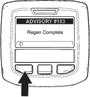
When the engine computer completes a parked or recovery regeneration, the InfoCenter displays ADVISORY #183 (Figure 58). Press the left button to exit to the home screen.
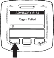
Note: If the regeneration fails to complete, the InfoCenter displays Advisory #184 (Figure 58). Press the left button to exit to the home screen.
Canceling a Parked or Recovery Regeneration
Use the Parked Regen Cancel or Recovery Regen Cancel setting to cancel a running parked or recovery regeneration process.
Operating Tips
Using the Fast Throttle Setting
To maintain enough power for the machine and deck while mowing, operate the engine at the fast throttle position and adjust your ground speed for conditions.
Selecting the Ground Speed
To improve cut quality, use a slower ground speed. Decrease the ground speed as the load on the cutting blades increases, and increase ground speed as load on the blades decreases.
Alternating Mowing Direction
Alternate mowing direction to avoid making ruts in the turf over time. This also helps disperse clippings which enhances decomposition and fertilization.
Avoiding Cutting Too Low
If the cutting width of the mower is wider than the mower you previously used, raise the cutting height to ensure that uneven turf is not cut too short.
Selecting the Proper Height of Cut to Suit Conditions
Remove approximately 25 mm (1 inch) or no more than 1/3 of the grass blade when cutting. In exceptionally lush and dense grass, you may have to slow down the forward speed and/or raise the height of cut to the next higher setting.
Important: If cutting more than 1/3 of the grass blade off, or in sparse long grass or dry conditions, the use of flat sail blades is recommended to reduce air-borne chaff, debris, and unnecessary strain on deck-drive components.
Cutting Long Grass
If the grass is ever allowed to grow slightly longer than normal, or if it contains a high degree of moisture, raise the cutting height higher than usual and cut the grass at this setting. Then cut the grass again using the lower, normal setting.
Keeping the Mower Clean
Clean clippings and dirt from the underside of the mower after each use. If grass and dirt build up inside the mower, cutting quality will eventually become unsatisfactory.
To reduce the risk of fire, keep the engine, muffler, battery compartment, parking brake, cutting units, and fuel storage compartment free of grass, leaves, or excessive grease. Clean up any spilled oil or fuel.
Maintaining the Blades
Maintain sharp blades throughout the cutting season because sharp blades cut cleanly without tearing or shredding the grass blades. Tearing and shredding turns grass brown at the edges, which slows growth and increases the chance of disease. Check the blades daily for sharpness and for any wear or damage. Sharpen the blades as necessary. If a blade is damaged or worn, replace it immediately with a genuine Toro replacement blade. Refer to Servicing the Cutting Blades in the mower-deck manual.
After Operation
After Operation Safety
-
Clean grass and debris from the cutting units, mufflers, and engine compartment to help prevent fires. Clean up oil or fuel spills.
-
If the cutting units are in the transport position, use the positive mechanical lock (if available) before you leave the machine unattended.
-
Allow the engine to cool before storing the machine in any enclosure.
-
Remove the key and shut off the fuel (if equipped) before storing or transporting the machine.
-
Never store the machine or fuel container where there is an open flame, spark, or pilot light, such as on a water heater or on other appliances.
-
Keep all parts of the machine in good working condition and all hardware tightened, especially blade-attachment hardware.
-
Replace all worn or damaged decals.
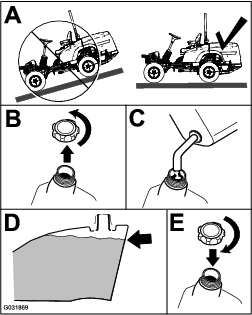
Pushing the Machine by Hand
If the machine stalls or runs out of fuel, you may need to push it. You must first open both of the hydraulic bypass valves.
Important: Always push the machine by hand and never a long distance. Never tow the machine, because damage to the hydraulic system may occur.
Pushing the Machine
-
Disengage the power takeoff (PTO), turn the key to the OFF position, remove the key, and engage the parking brake.
-
Lift the seat.
-
Rotate each bypass valve counterclockwise 1 turn (Figure 62).
Note: This allows hydraulic fluid to bypass the pump, enabling the wheels to turn.
Important: Do not rotate the bypass valves more than 1 turn. This prevents the valves from coming out of the body and causing fluid to run out.
-
Disengage the parking brake before pushing the machine.
Hauling the Machine
-
Use care when loading or unloading the machine into a trailer or a truck.
-
Use full-width ramps for loading the machine into a trailer or a truck.
-
Tie the machine down securely using straps, chains, cable, or ropes. Both front and rear straps should be directed down and outward from the machine.
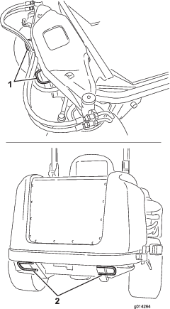
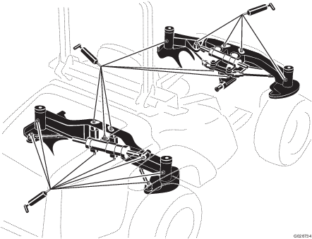
Locating the Tie-Down Points
There are tie downs located at the front and rear sides of the machine (Figure 63).
Note: Use properly-rated DOT-approved straps in 4 corners to tie down the machine.
-
2 on the front of the operator's platform
-
Rear tire
Maintenance
Note: Determine the left and right sides of the machine from the normal operating position.
Recommended Maintenance Schedule(s)
| Maintenance Service Interval | Maintenance Procedure |
|---|---|
| After the first 10 hours |
|
| After the first 200 hours |
|
| Before each use or daily |
|
| Every 50 hours |
|
| Every 100 hours |
|
| Every 200 hours |
|
| Every 250 hours |
|
| Every 400 hours |
|
| Every 800 hours |
|
| Every 1,500 hours |
|
| Every 6,000 hours |
|
| Every 2 years |
|
Important: Refer to your engine owner's manual for additional maintenance procedures. A detailed Service Manual is also available for purchase from your authorized Toro distributor.
Note: To obtain an electrical schematic or a hydraulic schematic for your machine, visit www.Toro.com.
Pre-Maintenance Procedures
Maintenance Safety
-
Before adjusting, cleaning, repairing, or leaving the machine, do the following:
-
Park the machine on a level surface.
-
Move the throttle switch to the low-idle position.
-
Disengage the cutting units.
-
Lower the cutting units.
-
Ensure that the traction is in neutral.
-
Engage the parking brake.
-
Shut off the engine and remove the key.
-
Wait for all moving parts to stop.
-
Allow machine components to cool before performing maintenance.
-
-
If the cutting units are in the transport position, use the positive mechanical lock (if available) before you leave the machine unattended.
-
If possible, do not perform maintenance while the engine is running. Keep away from moving parts.
-
Use jack stands to support the machine or components when required.
-
Carefully release pressure from components with stored energy.
Preparing the Machine for Maintenance
-
Ensure that the PTO is disengaged.
-
Park the machine on a level surface.
-
Engage the parking brake.
-
Lower the mower deck(s) and/or attachments if necessary.
-
Shut off the engine and wait for all moving parts to stop.
-
Turn the key to the STOP position and remove it.
-
Allow machine components to cool before performing maintenance.
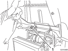
Using the Hood-Prop Rod
-
Release the hood latches.
-
Lift up the hood until you can position the prop rod behind the frame tube (Figure 64).
-
Lower the hood until the prop rod is in front of and resting against the frame tube.
-
To lower the hood, raise the hood until you can raise the prop rod above the frame tube, then lower the hood.
-
Secure the hood latches.
Lubrication
Greasing the Bearings and Bushings
| Maintenance Service Interval | Maintenance Procedure |
|---|---|
| Every 50 hours |
|
The machine has grease fittings that you must lubricate regularly with No. 2 lithium grease. Lubricate the grease fittings immediately after every washing, regardless of interval specified.
-
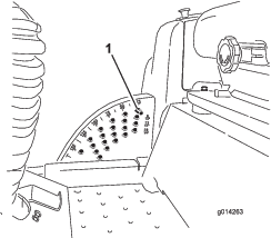
Wipe the grease fittings clean so that foreign matter cannot be forced into the bearing or bushing (Figure 65).
-
Pump the grease into the fittings.
-
Wipe off any excess grease.
Note: To access the grease fittings for the rear-steering linkage, remove the storage compartment.
Note: Raise the machine off the floor to allow better grease migration through both the upper and lower king-pin bushings. You should see grease purging out of both the top and the bottom of the axle casting/bushing assembly areas of all 4 kingpin assemblies (Figure 66).
Note: The bearing life can be negatively affected by improper washing procedures. Do not wash the machine when it is still hot and avoid directing high-pressure or high-volume spray at the bearings or seals.
Engine Maintenance
Engine Safety
-
Shut off the engine and remove the key before checking the oil or adding oil to the crankcase.
-
Do not change the governor speed or overspeed the engine.
Servicing the Air Cleaner
| Maintenance Service Interval | Maintenance Procedure |
|---|---|
| Before each use or daily |
|
| Every 400 hours |
|
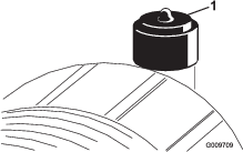
Check the air-cleaner body for damage, which could cause an air leak. Replace it if it is damaged. Check the whole intake system for leaks, damage, or loose hose clamps.
Service the air-cleaner filter only when the service indicator requires it (Figure 67). Changing the air filter before it is necessary only increases the chance of dirt entering the engine when you remove the filter.
Important: Be sure that the cover is seated correctly and seals with the air-cleaner body.
-
Replace the air cleaner (Figure 68).
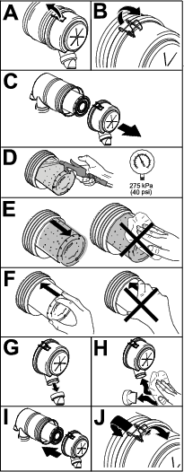
Note: Do not clean the used element due to the possibility of damage to the filter media.
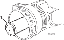
Important: Never attempt to clean the safety filter (Figure 69). Replace the safety filter after every 3 primary filter services.
-
Reset the indicator (Figure 67) if it shows red.
Servicing the Engine Oil
Oil Specification
Use high-quality, low-ash engine oil that meets or exceeds the following specifications:
-
API service category CJ-4 or higher
-
ACEA service category E6
-
JASO service category DH-2
Important: Using engine oil other than API CJ-4 or higher, ACEA E6, or JASO DH-2 may cause the diesel particulate filter to plug or cause engine damage.
Use the following engine oil viscosity grade:
-
Preferred oil: SAE 15W-40 (above 0°F)
-
Alternate oil: SAE 10W-30 or 5W-30 (all temperatures)
Toro Premium Engine Oil is available from your Authorized Toro Distributor in either 15W-40 or 10W-30 viscosity grades. See the parts catalog for part numbers.
Checking the Engine-Oil Level
| Maintenance Service Interval | Maintenance Procedure |
|---|---|
| Before each use or daily |
|
The engine is shipped with oil in the crankcase; however, the oil level must be checked before and after the engine is first started.
Important: Check the engine oil daily. If the engine-oil level is above the Full mark on the dipstick, the engine oil may be diluted with fuel;If the engine oil level is above the Full mark, change the engine oil.
The best time to check the engine oil is when the engine is cool before it has been started for the day. If it has already been run, allow the oil to drain back down to the sump for at least 10 minutes before checking. If the oil level is at or below the Add mark on the dipstick, add oil to bring the oil level to the Full mark. Do not overfill the engine with oil.
Important: Keep the engine oil level between the upper and lower limits on the dipstick; the engine may fail if you run it with too much or too little oil.
-
Park the machine on a level surface.
-
Check the engine-oil level (Figure 70).
Note: When using different oil, drain all old oil from the crankcase before adding new oil.
Crankcase Oil Capacity
5.2 L (5.5 US qt) with the filter.
Changing the Engine Oil and Filter
| Maintenance Service Interval | Maintenance Procedure |
|---|---|
| Every 250 hours |
|
-
Start the engine and let it run 5 minutes to allow the oil to warm up.
-
Park the machine on a level surface, engage the parking brake, shut off the engine, remove the key.
-
Replace the engine oil and filter (Figure 71).
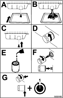
-
Add oil to the crankcase; refer to Checking the Engine-Oil Level.
Servicing the Diesel-Oxidation Catalyst (DOC) and the Soot Filter
| Maintenance Service Interval | Maintenance Procedure |
|---|---|
| Every 6,000 hours |
|
-
If advisory message displays in the InfoCenter, the DPF is nearing the recommended point for servicing the diesel-oxidation catalyst and the soot filter.
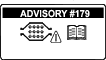
-
If engine faults , , or in the InfoCenter (Figure 73) display in the InfoCenter, clean the soot filter using the steps that follow:
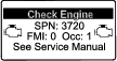
-
Refer to the Engine section in the Service Manual for information on disassembling and assembling the diesel-oxidation catalyst and the soot filter of the DPF.
-
Refer to your Authorized Toro Distributor for diesel-oxidation catalyst and the soot filter replacement parts or service.
-
Contact your Authorized Toro Distributor to have them reset the engine ECU after you install a clean DPF.
-
Fuel System Maintenance
Note: Refer to Fuel Specification for the proper fuel recommendations.
Danger
Under certain conditions, diesel fuel and fuel vapors are highly flammable and explosive. A fire or explosion from fuel can burn you and others and can cause property damage.
-
Use a funnel and fill the fuel tank outdoors, in an open area, when the engine is off and is cold. Wipe up any fuel that spills.
-
Do not fill the fuel tank completely full. Add fuel to the fuel tank until the level is to the bottom of the filler neck.
-
Never smoke when handling fuel and stay away from an open flame or where a spark my ignite fuel fumes.
-
Store fuel in a clean, safety-approved container and keep the cap in place.
Servicing the Water Separator
| Maintenance Service Interval | Maintenance Procedure |
|---|---|
| Before each use or daily |
|
| Every 400 hours |
|
Service the water separator as shown in Figure 74.
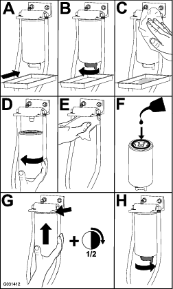
Servicing the Engine Fuel Filter
| Maintenance Service Interval | Maintenance Procedure |
|---|---|
| Every 400 hours |
|
-
Clean the area around the filter head (Figure 75).
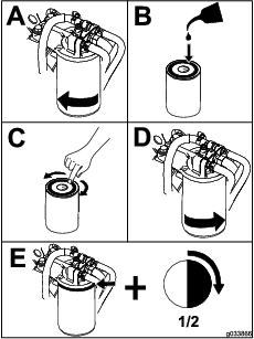
-
Start the engine and check for fuel leaks around the filter head.
Checking the Fuel Lines and Connections
| Maintenance Service Interval | Maintenance Procedure |
|---|---|
| Every 400 hours |
|
Inspect the fuel lines and connections for deterioration, damage, or loose connections.
Cleaning the Fuel Pick-Up Tube Screen
The fuel pick-up tube, located inside the fuel tank, is equipped with a screen to help prevent debris from entering the fuel system. Remove the fuel pick-up tube and clean the screen as required.
Electrical System Maintenance
Important: Whenever working with the electrical system, always disconnect the battery cables, negative (-) cable first, to prevent possible wiring damage from short-outs.
Electrical System Safety
Warning
Battery posts, terminals, and related accessories contain lead and lead compounds, chemicals known to the State of California to cause cancer and reproductive harm. Wash hands after handling.
-
Disconnect the battery before repairing the machine. Disconnect the negative terminal first and the positive last. Connect the positive terminal first and the negative last.
-
Charge the battery in an open, well-ventilated area, away from sparks and flames. Unplug the charger before connecting or disconnecting the battery. Wear protective clothing and use insulated tools.
Checking the Fuses
If the machine stops or has other electrical-system issues, check the fuses. Grasp each fuse in turn and remove them 1 at a time, checking to see if any are blown. If you need to replace a fuse, always use the same type and amperage rated fuse as the 1 you are replacing; otherwise, you could damage the electrical system (refer to the decal next to the fuses for a diagram of each fuse and its amperage).
Tilt the seat forward, and pull the panel off to access the fuses (Figure 76).
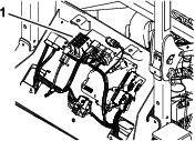
The fuse block for attachments are located under the seat (Figure 77).
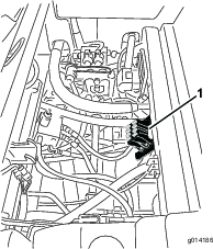
The cab fuses are located in the fuse box on the cab headliner (Figure 78).
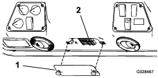
Servicing the Battery
| Maintenance Service Interval | Maintenance Procedure |
|---|---|
| Every 50 hours |
|
Keep the top of the battery clean. If you store the machine in a location where temperatures are extremely high, the battery will run down more rapidly than if the machine is stored in a location where temperatures are cool.
Keep the top of the battery clean by washing it periodically with a brush dipped in ammonia or baking-soda solution. Flush the top surface with water after cleaning it. Do not remove the fill caps while cleaning the battery.
The battery cables must be tight on the terminals to provide good electrical contact.
If corrosion occurs at the terminals, disconnect the cables, negative (-) cable first, and scrape the clamps and terminals separately. Connect the cables, positive (+) cable first, and coat the terminals with petroleum jelly.
Warning
Battery terminals or metal tools could short against metal machine components, causing sparks. Sparks can cause the battery gasses to explode, resulting in personal injury.
-
When removing or installing the battery, do not allow the battery terminals to touch any metal parts of the machine.
-
Do not allow metal tools to short between the battery terminals and metal parts of the machine.
Warning
Incorrect battery cable routing could damage the machine and cables causing sparks. Sparks can cause the battery gasses to explode, resulting in personal injury.
-
Always disconnect the negative (black) battery cable before disconnecting the positive (red) cable.
-
Always connect the positive (red) battery cable before connecting the negative (black) cable.
Storing the Battery
If the machine will be stored more than 30 days, remove the battery and charge it fully. Either store it on a shelf or on the machine. Leave the cables disconnected if it is stored on the machine. Store the battery in a cool atmosphere to avoid quick deterioration of the charge in the battery. To prevent the battery from freezing, make sure that it is fully charged. The specific gravity of a fully charged battery is 1.265 to 1.299.
Drive System Maintenance
Checking the Tire Pressure
| Maintenance Service Interval | Maintenance Procedure |
|---|---|
| Every 50 hours |
|
Maintain the air pressure in the front and rear tires. The correct air pressure is 172 kPa (25 psi) in the rear tires and 103 kPa (15 psi) in the front tires. If a cab is installed on the machine, the front and rear tires should be inflated to 172 kPa (25 psi). Uneven tire pressure can cause an uneven cut. Check the tires when they are cold to get the most accurate pressure reading.
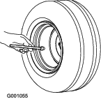
Correcting Steering Misalignment
-
Press the steering selector switch to the rearward 4-wheel-steer position (Figure 80).
-
On a paved or dirt surface, turn the steering wheel to the left or right and continue turning until all 4 wheels have stopped turning. Automatic synchronization of wheel alignment should occur.
Important: Doing this procedure on turf can result in turf directly under each of the turning tires.
Cooling System Maintenance
Cooling System Safety
-
Swallowing engine coolant can cause poisoning; keep out of reach from children and pets.
-
Discharge of hot, pressurized coolant or touching a hot radiator and surrounding parts can cause severe burns.
-
Always allow the engine to cool at least 15 minutes before removing the radiator cap.
-
Use a rag when opening the radiator cap, and open the cap slowly to allow steam to escape.
-
-
Do not operate the machine without the covers in place.
-
Keep your fingers, hands and clothing clear of rotating fan and drive belt.
-
Shut off the engine and remove the key before performing maintenance.
Checking the Cooling System
| Maintenance Service Interval | Maintenance Procedure |
|---|---|
| Before each use or daily |
|
The cooling system is filled with a 50/50 solution of water and permanent ethylene glycol anti freeze. Check the level of the coolant in the expansion tank at the beginning of each day before starting the engine. The capacity of the cooling system is 7.5 L (6 US qt).
-
Check the level of the coolant in the expansion tank (Figure 81). The coolant level should be between the marks on the side of the tank.
-
If coolant level is low, remove the expansion tank cap and replenish the system. Do not overfill.
-
Install the expansion-tank cap.
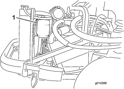
Cleaning the Radiator
| Maintenance Service Interval | Maintenance Procedure |
|---|---|
| Before each use or daily |
|
| Every 200 hours |
|
| Every 1,500 hours |
|
| Every 2 years |
|
Keep the radiator clean to prevent the engine from overheating.
Note: If the attachment or engine shuts off due to overheating, first check the radiator for an excessive buildup of debris.
-
Open the hood and secure the prop rod.
-
Loosen the flange nut securing the clean-out cover to the underside of the rear frame (Figure 82). Rotate the cover to the side to expose the clean-out hole in the frame.
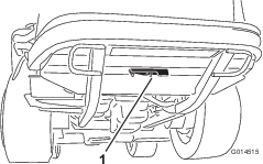
-
Working from the fan side of the radiator, blow out debris with low-pressure (50 psi) compressed air (do not use water). Repeat this step from the front of the radiator, again from the fan side.
-
After you have thoroughly cleaned the radiator, remove any debris from the channel at the radiator base and around the frame.
-
Clean the engine compartment and the brake linkage.
-
Close the clean-out cover and secure the flange nut.
-
Close the hood.
Brake Maintenance
Adjusting the Brakes
Adjust the service brakes when there is more than 25 mm (1 inch) of free travel of the brake pedal, or when the brakes do not work effectively. Free travel is the distance that the brake pedal moves before you feel braking resistance.
Note: Use the wheel-motor backlash to rock the drums back and forth to ensure that the drums are free prior to and after adjustment.
-
To reduce free travel of the brake pedals, tighten the brakes by loosening the front nut on the threaded end of the brake cable (Figure 83).
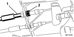
-
Tighten the rear nut to move the cable backward until brake pedals have 1.27 to 1.9 cm (1/2 to 3/4 inch) of free travel before the wheels lock up.
-
Tighten the front nuts, ensuring that both cables actuate the brakes simultaneously.
Adjusting the Parking Brake
If the parking brake fails to engage, an adjustment to the brake pawl is required.
-
Loosen the 2 screws securing the parking-brake pawl to the frame (Figure 84).
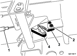
-
Press the parking-brake pedal forward until the brake detent completely engages on the brake pawl (Figure 84).
-
Tighten the 2 screws to lock the adjustment.
-
Press the brake pedal to release the parking brake.
-
Check the adjustment and adjust it again as required.
Belt Maintenance
Checking the Alternator Belt
| Maintenance Service Interval | Maintenance Procedure |
|---|---|
| After the first 10 hours |
|
| Every 100 hours |
|
Check the condition and tension of the belt (Figure 85) after every 100 operating hours.
-
Ensure that the proper tension allows 10 mm (3/8 inch) deflection when a force of 4.4 kg (10 lb) is applied on the belt midway between the pulleys.
-
If the deflection is not 10 mm (3/8 inch), loosen the alternator mounting bolts (Figure 85). Increase or decrease the tension of the alternator belt and tighten the bolts. Check the deflection of the belt again to ensure that the tension is correct.
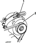
Controls System Maintenance
Adjusting the Traction Drive for Neutral
Note: If the machine has recently had the hydraulic fluid changed or the traction motors or hoses replaced, work out any air trapped in the system prior to performing this procedure. To do this, operate the machine in forward and reverse for a few minutes and then replenish the oil as required.
Note: When positioned on a level surface, the machine must not creep when you release the traction pedal.
-
Park the machine on a level surface, engage the parking brake, lower the cutting unit to the floor, and shut off the engine.
-
Jack up the rear of the machine until the rear tires are off the shop floor. Support the machine with jack stands to prevent it from falling.
Note: On 4-wheel-drive models, the front tires must also be off the shop floor and supported by jack stands.
Warning
The engine must be running so that you can perform this adjustment. This could cause personal injury.
Keep your hands, feet, face, and other body parts away from any hot parts of the engine and any rotating parts.
-
Start the engine, set the throttle to the SLOW position, and observe which direction the rear tires rotate.
Important: Make sure that the traction pedal is in the NEUTRAL position.
-
If the left rear tire is rotating, loosen the jam nuts on the left side transmission control rod (Figure 86).
Note: The forward end of the control rod has a left-hand thread. The rear end of the rod, which is connected to the transmission, has a right-hand thread.
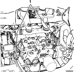
-
If the left rear tire is rotating in reverse, lengthen the rod by slowly turning the rod counterclockwise (as viewed from the front) until the left rear tire stops rotating or has minimal rotation in reverse.
-
If the left rear tire is rotating forward, shorten the rod by slowly turning the rod clockwise (as viewed from the front) until the left rear tire stops rotating.
-
-
Move the throttle to the FAST position. Make sure that the wheel remains stopped or has minimal rotation in reverse. Adjust it as required.
-
Tighten the jam nuts.
-
Repeat the procedure for the right rear tire, if required, by using the right-side transmission control rod.
-
Shut off the engine, remove the jack stands, and lower the machine to the shop floor.
-
Test drive the machine to make sure that it does not creep.
Adjusting the Maximum Ground Speed
-
Park the machine on a level surface, disengage the PTO, release the traction pedal to the NEUTRAL position, and engage the parking brake.
-
Move the throttle lever to the SLOW position, shut off the engine, remove the key, and wait for all moving parts to stop before leaving the operating position.
-
Loosen the jam nut on the stop bolt for the traction pedal (Figure 87).
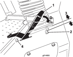
-
Adjust the stop bolt all the way in (away from the traction pedal).
-
Using your hand, push the traction pedal all the way forward, with light pressure, until it stops and hold it there.
Note: Maintain only light pressure on the pedal when pushing it to the full forward position.
-
With the seat in the raised position, verify that you are not over loading the linkage by making sure the transmission does not move when you press the pedal to the stop.
-
Adjust the stop bolt out (toward the traction pedal) until there is a gap of 1.5 mm (0.060 inch) between the head of the stop bolt and the bottom of the traction pedal.
-
Tighten the jam nut to secure the stop bolt in place.
-
To change the reverse speed, you can adjust the reverse stop bolt. To increase the reverse speed, adjust the stop bolt in; to decrease the reverse speed, adjust the stop bolt out.
Hydraulic System Maintenance
Hydraulic System Safety
-
Seek immediate medical attention if fluid is injected into skin. Injected fluid must be surgically removed within a few hours by a doctor.
-
Ensure that all hydraulic-fluid hoses and lines are in good condition and all hydraulic connections and fittings are tight before applying pressure to the hydraulic system.
-
Keep your body and hands away from pinhole leaks or nozzles that eject high-pressure hydraulic fluid.
-
Use cardboard or paper to find hydraulic leaks.
-
Safely relieve all pressure in the hydraulic system before performing any work on the hydraulic system.
Checking the Hydraulic System
| Maintenance Service Interval | Maintenance Procedure |
|---|---|
| Before each use or daily |
|
The reservoir is filled at the factory with approximately 17 L (18 US qt) of high-quality tractor transmission/hydraulic fluid. The recommended replacement fluid is as follows:
Toro Premium Transmission/Hydraulic Tractor Fluid (Available in 19 L (5 gallon) pails or 208 L (55 gallon) drums. See the Parts Catalog or your Toro Distributor for part numbers).
Alternate fluids: If the Toro fluid is not available, Mobil® 424 hydraulic fluid may be used.
Note: Toro will not assume responsibility for damage caused by improper substitutions.
Note: Many hydraulic fluids are almost colorless, making it difficult to spot leaks. A red dye additive for the hydraulic system oil is available in 20 ml (2/3 fl oz) bottles. One bottle is sufficient for 15 to 22 L (4 to 6 US gallons) of hydraulic fluid. Order Part No. 44-2500 from your authorized Toro distributor.
-
Park the machine on a level surface, release the traction pedal to the NEUTRAL position, and start the engine.
-
Run the engine at the lowest possible speed to purge the system of air.
Important: Do not engage the PTO.
-
Raise the deck to extend the lift cylinders, shut off the engine, and remove the key.
-
Remove the hydraulic-filler cap (Figure 88) from the filler neck.
-
Remove the dipstick and wipe it with a clean rag (Figure 88).
-
Screw the dipstick all the way into the filler neck; then remove it, and check the level of the fluid (Figure 88).
If the level is not within the notched area of the dipstick, add enough high-quality hydraulic fluid to raise the level to within the notched area. Do not overfill the hydraulic system.
-
Replace the dipstick and thread the fill cap finger-tight onto the filler neck.
-
Check all hoses and fittings for leaks.
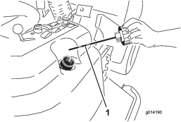
Changing the Hydraulic Fluid And Filter
| Maintenance Service Interval | Maintenance Procedure |
|---|---|
| After the first 200 hours |
|
| Every 800 hours |
|
-
Disengage the PTO, release the traction pedal to the NEUTRAL position, and engage the parking brake.
-
Move the throttle lever to the SLOW position, shut off the engine, remove the key, and wait for all moving parts to stop before leaving the operating position.
-
Place a large pan under the hydraulic reservoir and transmission case and remove the plugs, draining all of the hydraulic fluid (Figure 89).
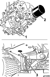
-
Clean the area around the hydraulic-fluid filter and remove the filter (Figure 89).
-
Immediately install a new hydraulic-fluid filter.
-
Install the drain plugs in the hydraulic reservoir and the transmission case.
-
Fill the reservoir to the proper level; refer to Checking the Hydraulic System.
-
Start the engine and check for fluid leaks. Allow the engine to run for about 5 minutes, then shut it off.
-
After 2 minutes, check the level of the hydraulic fluid; refer to Checking the Hydraulic System.
Cab Maintenance
Filling the Washer-Fluid Bottle
-
Perform the pre-maintenance procedure; refer to Preparing the Machine for Maintenance.
-
Open the hood and locate the washer-fluid bottle (Figure 90).
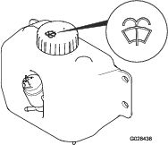
-
Fill the bottle with washer fluid as needed.
-
Close the hood.
Cleaning the Cab Air Filters
| Maintenance Service Interval | Maintenance Procedure |
|---|---|
| Every 250 hours |
|
-
Remove the screws and grates from over both the in-cab and rear cab air filters (Figure 91 and Figure 92).
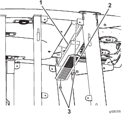
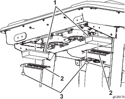
-
Clean the filters by blowing clean, oil-free, compressed air through them.
Important: If either filter has a hole, tear, or other damage, replace it.
-
Install the filters and grate, securing them with the thumbscrews.
Cleaning the Air-Conditioning Coil
| Maintenance Service Interval | Maintenance Procedure |
|---|---|
| Every 50 hours |
|
-
Perform the pre-maintenance procedure; refer to Preparing the Machine for Maintenance.
-
Lift the 4 tabs on the air-conditioning screen (Figure 93) and remove the screen from the top of the cab.
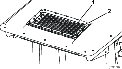
-
Disconnect the plug and cord for the fans from the outlet (Figure 94).
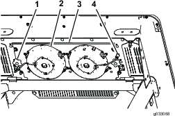
-
Remove the 2 knobs that secure the fan-panel assembly and fans to the underside of the cab top (Figure 94) and remove the assembly.
-
Clean the screen, air-conditioning duct, fans, and fan panel using low-pressure air no greater than 276 kPa (40 psi).
Important: Do not use water to clean the condenser because moisture on the components attracts dirt and dust, which make the components more difficult to clean.
-
Install the fan-panel assembly and fans to the underside of the cab top with the 2 knobs that you loosened and removed in step 4.
-
Connect the cord for the fans that you disconnected in step 3 into the outlet.
-
Install the air-conditioning screen in the opening in the top of the cab and secure it by closing the 4 tabs on the screen.
Cleaning
Cleaning the Cab
Important: Use care around the cab seals and lights (Figure 95). If you are using a pressure washer, keep the washer wand at least 0.6 m (2 ft) away from the machine. Do not use the pressure washer directly on the cab seals and lights or under the rear overhang.
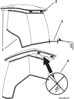
Disposing of Waste
Engine oil, batteries, hydraulic fluid, and engine coolant are pollutants to the environment. Dispose of these according to your state and local regulations.
Storage
Preparing the Engine
-
Drain the engine oil from the oil pan and install the drain plug.
-
Change the engine oil and filter; refer to Changing the Engine Oil and Filter.
-
Fill the engine with the designated quantity of engine oil; refer to Crankcase Oil Capacity.
-
Start the engine and run it at idle speed for 2 minutes.
-
Drain the fuel from the fuel tank, fuel lines, pump, filter, and separator. Flush the fuel tank with clean diesel fuel and connect all fuel lines.
-
Thoroughly clean and service the air-cleaner assembly.
-
Seal the air-cleaner inlet and the exhaust outlet with weatherproof masking tape.
-
Check the oil-filler cap and fuel-tank cap to ensure that they are securely in place.
Preparing the Machine
-
Thoroughly clean the machine, the deck, and the engine, paying special attention to the following areas:
-
Radiator and radiator screen
-
Counterbalance springs
-
PTO-shaft assembly
-
All grease fittings and pivot points
-
Inside of the control box (Remove the control panel for access.)
-
Beneath the seat plate and the top of the transmission
-
-
Check and adjust the tire pressure; refer to Checking the Tire Pressure.
-
Check all fasteners for looseness and tighten them as necessary.
-
Grease or oil all grease fittings, pivot points, and transmission bypass-valve pins. Wipe off any excess lubricant.
-
Lightly sand and use touch-up paint on painted areas that are scratched, chipped, or rusted. Repair any dents in the metal body.
-
Service the battery and cables as follows:
-
Remove the battery terminals from the battery posts.
-
Clean the battery, terminals, and posts with a wire brush and baking-soda solution.
-
Coat the cable terminals and battery posts with Grafo 112X skin-over grease (Toro Part No. 505-47) or petroleum jelly to prevent corrosion.
-
Slowly charge the battery for 24 hours every 60 days to prevent lead sulfation of the battery.
-