| Maintenance Service Interval | Maintenance Procedure |
|---|---|
| Every 50 hours |
|
| Every 400 hours |
|
Introduction
This rotary-blade lawn cutting deck is mounted to a ride-on machine and is intended to be used by professional, hired operators in commercial applications. It is primarily designed for cutting grass on well-maintained lawns in parks, sports fields, and on commercial grounds. It is not designed for cutting brush.
Important: To maximize the safety, performance, and proper operation of this machine, carefully read and fully understand the contents of this Operator’s Manual. Failing to follow these operating instructions or to receive proper training may result in injury. For more information on safe operating practices, including safety tips and training materials, go to www.Toro.com.
You may contact Toro directly at www.Toro.com for product and accessory information, help finding a dealer, or to register your product.
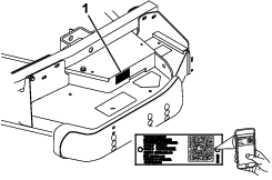
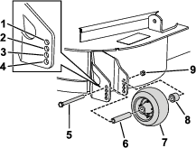
Whenever you need service, genuine Toro parts, or additional information, contact an Authorized Service Dealer or Toro Customer Service and have the model and serial numbers of your product ready. Figure 1 identifies the location of the model and serial numbers on the product. Write the numbers in the space provided.
Important: With your mobile device, you can scan the QR code on the serial number decal (if equipped) to access warranty, parts, and other product information.
This manual identifies potential hazards and has safety messages identified by the safety-alert symbol (Figure 2), which signals a hazard that may cause serious injury or death if you do not follow the recommended precautions.

This manual uses 2 words to highlight information. Important calls attention to special mechanical information and Note emphasizes general information worthy of special attention.
This product complies with all relevant European directives. For details, please see the Declaration of Incorporation (DOI) at the back of this publication.
Warning
CALIFORNIA
Proposition 65 Warning
Use of this product may cause exposure to chemicals known to the State of California to cause cancer, birth defects, or other reproductive harm.
Safety
This machine has been designed in accordance with EN ISO 5395-3:2013 and ANSI B71.4-2017.
General Safety
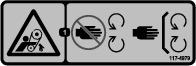
This product is capable of amputating hands and feet and of throwing objects. Always follow all safety instructions to avoid serious personal injury.
Using this product for purposes other than its intended use could prove dangerous to you and bystanders.
-
Read and understand the contents of this Operator’s Manual before starting the engine.
-
Use your full attention while operating the machine. Do not engage in any activity that causes distractions; otherwise, injury or property damage may occur.
-
Do not put your hands or feet near moving components of the machine.
-
Do not operate the machine without all guards and other safety protective devices in place and working on the machine.
-
Keep clear of any discharge opening. Keep bystanders and pets a safe distance away from the machine.
-
Keep children out of the operating area. Never allow children to operate the machine.
-
Park the machine on a level surface, lower the cutting units, disengage the drives, engage the parking brake (if provided), shut off the engine, and remove the key before leaving the operator's position for any reason.
Improperly using or maintaining this machine can result in injury. To reduce the potential for injury, comply with these safety instructions and always pay attention to the safety-alert symbol, which means Caution, Warning, or Danger—personal safety instruction. Failure to comply with these instructions may result in personal injury or death.
You can find additional safety information where needed throughout this Operator’s Manual.
Safe Operating Practices
-
Read the Operator’s Manual for the traction unit and other training material carefully. Be familiar with the controls, safety signs, and the proper use of the equipment. If the operator or mechanic cannot read the language of this manual, it is the owner's responsibility to explain this material to them.
-
Become familiar with the safe operation of the equipment, operator controls, and safety signs.
-
The owner/operator can prevent and is responsible for accidents that may cause personal injury or property damage.
-
Wear appropriate clothing, including eye protection; substantial, slip-resistant footwear; long pants, and hearing protection. Tie back long hair and do not wear loose jewelry.
-
Inspect the area where the equipment is to be used and remove all objects, such as rocks, toys, and wire, that the machine can throw.
-
Check that operator's presence controls, safety switches, and shields are attached and functioning properly. Do not operate the machine unless they are functioning properly.
-
Stop the machine, remove the key, and wait for all moving parts to stop before inspecting the attachment after striking an object or if there is an abnormal vibration in the machine. Make all necessary repairs before resuming operation.
-
Keep your hands and feet away from the cutting units.
-
Keep all parts in good working condition and all hardware tightened. Replace all worn or damaged decals.
-
A worn or damaged blade can break, and a piece of the blade could be thrown toward you or bystanders, resulting in serious personal injury or death.
-
Inspect the blade periodically for wear or damage.
-
Use care when checking the blades. Wrap the blades or wear gloves, and use caution when servicing the blades. Only replace or sharpen the blades; never straighten or weld them.
-
On multi-bladed machines, take care as rotating 1 blade can cause other blades to rotate.
-
Check the blade mounting bolts frequently to be sure that they are tightened to specification.
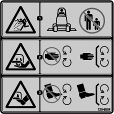
Safety and Instructional Decals
 |
Safety decals and instructions are easily visible to the operator and are located near any area of potential danger. Replace any decal that is damaged or missing. |


Setup
Warning
If you leave the key in the ignition switch, someone could accidentally start the engine and seriously injure you or other bystanders.
Remove the key from the ignition switch before you do any maintenance.
Danger
If the engine is started and the PTO shaft is allowed to rotate, serious injury could result.
Do not start the engine and engage the PTO switch when the PTO shaft is not connected to the gearbox on the cutting unit.
Note: Determine the left and right sides of the machine from the normal operating position.
Important: If the 72-inch Side-Discharge Cutting Unit (Model 31336) is being mounted to a Model 30307, 30308, 30309, 30343, 30344 or 30345 traction unit with a serial number prior to 311000301, install the Cutting Unit Alignment Kit (Part No. 120-6599) to mounting the cutting unit to the traction unit.
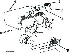
Securing the Grass Deflector
Model 31336 Only
Warning
An uncovered discharge opening could allow the machine to throw objects toward you or bystanders, resulting in serious injury. Also, contact with the blade could occur.
-
Do not operate the machine unless you install a cover plate, a mulch plate, or a grass chute and catcher.
-
Ensure that the grass deflector is in the down position.
-
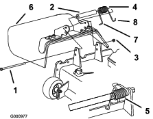
Remove the cable tie securing the grass deflector to the top of the deck and lower the deflector.
-
Place the left J-hook end of the spring around the deck edge
-
Place the right J-hook end of the spring around the grass deflector (Figure 3).
Important: You must be able to lower the grass deflector into position. Lift the deflector up to ensure that it lowers into the full down position.
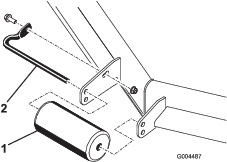
Installing the Lift Arms to the Traction Unit
Parts needed for this procedure:
| Right lift arm | 1 |
| Left lift arm | 1 |
-
On 1 side of the traction unit, loosen (but do not remove) the wheel nuts securing the wheel and tire assembly to the front wheel studs.
-
Jack up the machine until the front wheel is off the floor. Use jack stands or block the machine to prevent it from accidentally falling.
-
Remove the wheel nuts and slide the wheel and tire assembly off of the studs.
-
Remove the lift arms from the pallet.
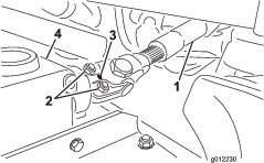
-
Remove the pivot pin and cotter pin from each lift arm.
-
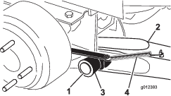
Mount a lift arm to the pivot bracket with a pivot pin and a cotter pin (Figure 4). Mount the lift arm with the bend positioned outward.
-
Hook the brake return spring to the tab on the lift arm (Figure 4).
-
Install the wheel and tire assembly. Torque the wheel nuts to 102 to 108 N∙m (75 to 80 ft-lb).
-
Repeat the procedure on the opposite side of the machine.
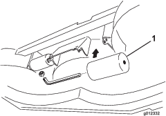
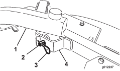
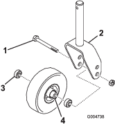
Connecting the Lift Arms to the Cutting Unit
-
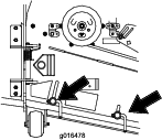
Remove the 2 thrust washers, clevis pin and hairpin cotter from each castor arm bracket on the cutting unit (Figure 5).
-
Move the cutting unit into position in front of the traction unit.
-
Press the lift switch forward to the FLOAT position. Push a lift arm down until the holes in the lift arm line up with the holes in the castor arm bracket (Figure 5).
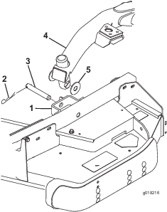
-
Secure the lift arm to the castor arm with the 2 thrust washers, a clevis pin and a hairpin cotter.
Position the thrust washers between the lift arm and the castor arm bracket (Figure 5) and insert end of cotter pin into the slot in the castor arm tab to retain cotter pin.
-
Repeat the procedure on the opposite lift arm.
-
Start the traction unit and raise the cutting unit.
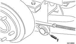
Connecting the PTO Shaft to the Cutting Unit Gearbox
-
Slide the male PTO shaft into the female PTO shaft, align the mounting holes in the gear case input shaft with the holes in the PTO shaft, and slide them together.
-
Secure them with a roll pin.
-
Tighten the bolts and nuts.
Greasing the Machine
Before operating the machine, it must be greased to ensure proper lubricating characteristics; refer to Lubrication. Failure to properly grease the machine will result in premature failure of critical parts.
Product Overview
Note: Specifications and design are subject to change without notice.
| Width of Cut | 1.829 m (72 inches) |
| Height of Cut | Adjustable from 25 to 127 mm (1 to 5 inches ) in 13 mm (1/2 inch) increments |
| Net Weight | Model 31335: 251 kg (553 lb) Model 31336: 292 kg (643 lb) |
Attachments/Accessories
A selection of Toro approved attachments and accessories is available for use with the machine to enhance and expand its capabilities. Contact your Authorized Service Dealer or Distributor or go to www.Toro.com for a list of all approved attachments and accessories.
To ensure optimum performance and continued safety certification of the machine, use only genuine Toro replacement parts and accessories. Replacement parts and accessories made by other manufacturers could be dangerous, and such use could void the product warranty.
Operation
Note: Determine the left and right sides of the machine from the normal operating position.
Caution
If you leave the key in the ignition switch, someone could accidently start the engine and seriously injure you or other bystanders.
Remove the key from the ignition before you do any maintenance.
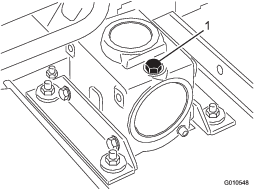
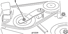
Checking the Lubricant in the Gearbox
The gearbox in designed to operate on SAE 80–90 weight gear lube. Although the gearbox comes with lubricant from the factory, check the level before operating the cutting unit. The gearbox capacity is 283 ml (12 fl oz).
-
Park the machine and cutting unit on a level surface.
-
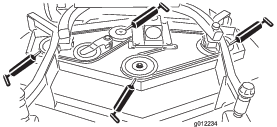
Remove the dipstick/fill plug from the top of the gearbox (Figure 7) and ensure that the lubricant is between the marks on the dipstick. If the lubricant level is low, add enough lubricant until the level is between the marks.
Adjusting the Height of Cut
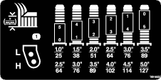
The height-of-cut is adjustable from 25 to 127 mm (1 to 5 inches) in 13 mm (1/2 inch) increments. To adjust the height-of-cut, position the castor wheel axles in the upper or lower holes of the castor forks and add or remove an equal number of spacers from the castor forks.
-
Start the engine and raise the cutting unit off the floor so that the height-of-cut can be changed. Shut off the engine and remove the key after the cutting unit is raised.
-
Position the castor wheel axles in the same holes in all castor forks. Refer to Figure 8, Figure 9 and Figure 10 to determine the correct holes for the setting.
Note: When operating in 64 mm (2-1/2 inch) height of cut or higher, the axle bolt must be installed in the lower castor fork hole to prevent grass buildup between the wheel and the fork. When operating in height of cuts lower than 64 mm (2-1/2 inches) and grass buildup is detected, reverse the machines direction to pull any clippings away from the wheel/fork area.
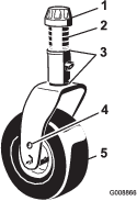
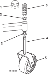
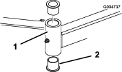
Front Castor Wheels
-
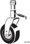
Remove the tensioning cap from the spindle shaft (Figure 8) and slide the spindle out of the castor arm.
-
Put the 2 shims (1/8 inch) onto the spindle shaft as they were originally installed. These shims are required to achieve a level across the entire width of the cutting units. Slide the appropriate number of 1/2-inch spacers onto the spindle shaft to get the desired height-of-cut, then slide the washer onto the shaft.
Refer to Figure 9 to determine the combinations of spacers for the setting.
-
Push the castor spindle through the castor arm. Install the shims (as they were originally installed) and the remaining spacers onto the spindle shaft. Install the tensioning cap to secure the assembly.
Note: When using 25 mm (1 inch), 38 mm (1-1/2 inch), or occasionally 51 mm (2 inch) height of cut, move the skids and roller to the highest holes.
Rear Castor Wheels
-
Remove the tensioning cap from the spindle shaft (Figure 10).
Note: The rear castor fork assembly does not need to be removed from the castor arm to change the height of cut.
-
Remove or add C-shaped spacers at the narrow portion of the spindle shaft, below the castor arm, to get the desired height of cut. Ensure that the shims, not the spacers, contact the top and bottom of the castor arm.
-
Install the tensioning cap to secure the assembly.
-
Ensure that all four castor wheels are set at the same height of cut.
Note: When using 25 mm (1 inch), 38 mm (1-1/2 inch), or occasionally 51 mm (2 inch) height of cut, move the skids and roller to the highest holes.
Adjusting the Rollers
Note: If you use the cutting unit at the 25 or 38 mm (1 or 1-1/2 inch) height-of-cut setting, reposition the cutting unit rollers in the top bracket holes.
-
Adjust the front rollers as follows:
-
Remove the screw and nut securing the roller shaft to the deck bracket (Figure 11).
-
Slide the shaft out of the lower bracket holes, align the roller with the top holes, and install the shaft.
-
Install the screw and nut to secure the assemblies.
-
-
Adjust the rear (internal) rollers as shown in Figure 12.
Adjusting the Skids
The skids should be mounted in the lower position when operating in height of cuts greater than 64 mm (2-1/2 inches) and in the higher position when operating in heights of cut lower than 64 mm (2-1/2 inches).
Adjust the skids by removing the flange bolt and nuts, positioning them as desired, and installing the fasteners (Figure 13).
Adjusting the Anti-Scalp Rollers
Model 31336 Only
Whenever you change the height-of-cut, adjust the height of the anti-scalp rollers.
-
After adjusting the height-of-cut, adjust the rollers by removing the flange nut, bushing, spacer, and bolt (Figure 14).
-
Select a hole so that the anti-scalp roller is positioned to the nearest corresponding height of cut desired.
-
Install the flange nut, bushing, spacer, and bolt. Torque to 54 to 61 N∙m (40 to 45 ft-lb) (Figure 14).
Adjusting the Flow Baffle
Model 31336 Only
You can adjust the mower discharge flow for different types of mowing conditions. Position the cam locks and baffle to give the best quality of cut.
-
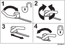
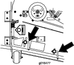
Adjust the cam locks by swinging the lever up to loosen the cam lock (Figure 15).
-
Adjust the baffle and cam locks in the slots to the desired discharge flow.
-
Swing the lever back over to tighten the baffle and cam locks (Figure 15).
-
If the cam locks do not lock the baffle into place or it is too tight, loosen the lever and then rotate the cam lock. Adjust the cam lock until you achieve the desired locking pressure.
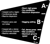
Positioning the Flow Baffle
Model 31336 Only
The following figures are recommendations only. Adjustments will vary by grass type, moisture content, and height of grass.
Note: If the engine power draws down and the mower ground speed is the same, open up the baffle.
Position A
This is the full rear position. The suggested use for this position is a follows:
-
Use for short, light grass mowing conditions
-
Use in dry conditions
-
For smaller grass clippings
-
Propels grass clippings farther away from the mower
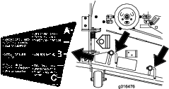
Position B
Use this position when bagging. Always align it with the blower opening.
Position C
This is the full open position. The suggested use for this position is as follows:
-
Use in tall, dense grass mowing conditions
-
Use in wet conditions
-
Lowers the engine power consumption
-
Allows increased ground speed in heavy conditions
Adjusting the Cutting Unit Pitch
Cutting unit pitch is the difference in height-of-cut from the front of the blade plane to the back of the blade plane. Use a blade pitch of 8 mm (5/16 inch). That is the back of the blade plane is 8 mm (5/16 inch) higher than the front.
-
Position the machine on a level surface on the shop floor.
-
Set the cutting unit to the desired height-of-cut.
-
Rotate 1 blade so that it points straight forward.
-
Use a short ruler to measure from the floor to the front tip of the blade. Rotate the blade tip to the rear and measure from the floor to the tip of the blade.
-
Subtract the front dimension from the rear dimension to calculate the blade pitch.
-
Adjust the shims, on the front or rear castor arms, to attain the required cutting unit pitch (Figure 19).
Correcting a Cutting Unit Mismatch
Due to differences in grass conditions and the counterbalance setting of the traction unit, it is advised that grass be cut and appearance checked before formal cutting is started.
-
Set the cutting unit to the desired height of cut; refer to Adjusting the Height of Cut.
-
Check and adjust front and rear tractor tire pressure to 138 kPa (20 psi).
-
Check and adjust all castor tire pressures to 345 kPa (50 psi).
-
Check for bent blades; refer to Checking for a Bent Blade.
-
Cut grass in a test area to determine if all cutting units are cutting at the same height.
-
If cutting unit adjustments are still needed, find a flat surface using a 2 m (6 ft) or longer straight edge.
-
To ease measuring blade plane, raise the height of cut to the highest position; refer to Adjusting the Height of Cut.
-
Lower the cutting unit onto the flat surface. Remove the covers from the top of the cutting units.
-
Rotate the blade on each spindle until the ends face forward and backward.
-
Measure from the floor to the front tip of the cutting edge.
-
Adjust the shims on the castor fork(s) to match the height of cut to the decal; refer to Adjusting the Height of Cut.
Using the Side Discharge
Model 31336 Only
The mower has a hinged grass deflector that disperses clippings to the side and down toward the turf.
Danger
Without a grass deflector, discharge cover, or complete grass catcher assembly mounted in place, you and others are exposed to blade contact and thrown debris. Contact with rotating mower blade(s) and thrown debris will cause injury or death.
-
Do not remove the grass deflector from the mower because the grass deflector routes material down toward the turf. If the grass deflector is ever damaged, replace it immediately.
-
Never put your hands or feet under the mower.
-
Never try to clear the discharge area or mower blades unless you move the power takeoff (blade-control switch (PTO) to the OFF position, rotate the ignition key to off and remove the key.
-
Ensure that the grass deflector is in the down position.
Operating Tips
Mowing only when the Grass Is Dry
Mow either in the late morning to avoid the dew, which causes grass clumping, or in late afternoon to avoid the damage that the direct sunlight can cause on the sensitive, freshly mowed grass.
Selecting the Proper Height-of-Cut Setting
Remove approximately 25 mm (1 inch) or no more than 1/3 of the grass blade when cutting. In exceptionally lush and dense grass, you may have to raise the height-of-cut to the next setting.
Mowing at the Proper Intervals
Under most normal conditions you will need to mow approximately every 4 or 5 days. But remember, grass grows at different rates at different times. This means that in order to maintain the same height of cut, which is a good practice, you will need to cut more frequently in early spring; as the grass growth rate slows in mid summer, cut only every 8 to 10 days. If you are unable to mow for an extended period due to weather conditions or other reasons, mow first at a higher height of cut; then mow again 2 or 3 days later with a lower height setting.
Mowing with Sharp Blades Only
A sharp blade cuts cleanly and without tearing or shredding the grass blades like a dull blade. Tearing and shredding causes the grass to turn brown at the edges, which impairs growth and increases susceptibility to diseases.
Cleaning the Underside of the Machine
To ensure optimum performance, clean the underside of the mower housing after each use. If residue is allowed to build up in the mower housing, cutting performance will decrease.
Setting the Cutting Unit Pitch
We recommend a blade pitch of 8 mm (5/16 inch). A pitch larger than 8 mm (5/16 inch) will result in less power required, larger clippings, and a poorer quality of cut. A pitch less than 8 mm (5/16 inch) will result in more power required, smaller clippings and a better quality of cut.
Maintenance
Recommended Maintenance Schedule(s)
| Maintenance Service Interval | Maintenance Procedure |
|---|---|
| After the first 2 hours |
|
| After the first 10 hours |
|
| Before each use or daily |
|
| Every 50 hours |
|
| Every 400 hours |
|
Caution
If you leave the key in the ignition switch, someone could accidentally start the engine and seriously injure you or other bystanders.
Remove the key from the ignition switch before you do any maintenance.
Lubrication
| Maintenance Service Interval | Maintenance Procedure |
|---|---|
| Before each use or daily |
|
| Every 50 hours |
|
The machine has grease fittings that you must lubricate regularly with No. 2 lithium grease.
-
Lubricate the following areas:
-
Position the machine and cutting unit on a level surface and lower the cutting unit. Remove the dipstick/fill plug from the top of the gearbox (Figure 24) and ensure that the lubricant is between the marks on the dipstick. If the lubricant level is low, add SAE 80-90 weight gear lube until the level is between the marks. The gearbox capacity is 283 ml (12 fl oz).
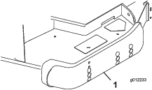
Removing the Cover
Important: The fasteners on the covers of this machine are designed to remain on the cover after removal. Loosen all the fasteners on each cover a few turns so that the cover is loose but still attached, then go back and loosen them until the cover comes free. This prevents you from accidentally stripping the bolts free of the retainers.
Separating the Cutting Unit from the Traction Unit
-
Park the machine on level surface, lower the cutting unit to the floor, move the lift lever to the FLOAT position, shut off the engine, and engage the parking brake.
-
Remove the hairpin cotters and clevis pins securing the lift arms to the castor arm brackets (Figure 25).
-
Roll the cutting unit away from the traction unit, separating the male and female sections of the PTO shaft (Figure 26).
Danger
If you start the engine and the PTO shaft is allowed to rotate, serious injury could result.
Do not start the engine and engage the PTO lever when the PTO shaft is not connected to the gearbox on the cutting unit.
Mounting the Cutting Unit to the Traction Unit
-
Position the machine on a level surface and shut the engine off.
-
Move the cutting unit into position in front of the traction unit.
-
Slide the male PTO shaft into the female PTO shaft (Figure 26).
-
Press the lift switch forward to the FLOAT position. Push a lift arm down until the holes in the lift arm line up with the holes in the castor arm bracket and you can insert the height-of-cut rod into the lift arm pads (Figure 27).
-
Secure the lift arm to the castor arm with 2 thrust washers, a clevis pin, and a hairpin cotter, position the thrust washers between the lift arm and the castor arm bracket (Figure 27), and insert end of cotter pin into the slot in the castor arm tab to retain cotter pin.
-
Repeat the procedure on the opposite lift arm.
-
Start the traction unit and raise the cutting unit.
Servicing the Bushings in the Castor Arms
The castor arms have bushings pressed into the top and bottom of the tube, and after many hours of operation, the bushings will wear.
To check the bushings, move the castor fork back and forth and from side to side. If the castor spindle is loose inside the bushings, the bushings are worn; replace them.
-
Raise the cutting unit so that the wheels are off of the floor. Block the cutting unit so that it cannot accidentally fall.
-
Remove the tensioning cap, spacer(s), and thrust washer from the top of the castor spindle.
-
Pull the castor spindle out of the mounting tube. Allow the thrust washer and spacer(s) to remain on the bottom of the spindle.
-
Insert a pin punch into the top or bottom of the mounting tube and drive the bushing out of the tube (Figure 28). Also, drive the other bushing out of the tube. Clean the inside of the tubes to remove dirt.
-
Apply grease to the inside and outside of the new bushings. Use a hammer and flat plate to drive the bushings into the mounting tube.
-
Inspect the castor spindle for wear and replace it if damaged.
-
Push the castor spindle through the bushings and mounting tube, slide the thrust washer and spacer(s) onto the spindle, and install the tensioning cap on the castor spindle.
Servicing the Castor Wheels and Bearings
| Maintenance Service Interval | Maintenance Procedure |
|---|---|
| After the first 2 hours |
|
| After the first 10 hours |
|
| Every 50 hours |
|
-
Remove the locknut from the bolt holding the castor wheel assembly between the castor fork (Figure 29). Grasp the castor wheel and slide the bolt out of the fork or pivot arm.
-
Remove the bearing from the wheel hub and allow the bearing spacer to fall out (Figure 29). Remove the bearing from the opposite side of the wheel hub.
-
Check the bearings, spacer, and inside of the wheel hub for wear. Replace any damaged parts.
-
To assemble the castor wheel, push the bearing into the wheel hub. When installing the bearings, press on the outer race of the bearing.
-
Slide the bearing spacer into the wheel hub. Push the other bearing into the open end of the wheel hub to captivate the bearing spacer inside the wheel hub.
-
Install the castor wheel assembly between the castor fork and secure it in place with the bolt and locknut.
Checking for a Bent Blade
-
Position the machine on a level surface. Raise the cutting unit, engage the parking brake, put the traction pedal in neutral, put the PTO lever in the OFF position, shut off the engine, and remove the ignition key. Block the cutting unit to prevent it from accidentally falling.
-
Rotate the blade until the ends face forward and backward. Measure from the inside of the cutting unit to the cutting edge at the front of the blade (Figure 30), and remember this dimension.

-
Rotate the opposite end of the blade forward. Measure between the cutting unit and cutting edge of the blade at the same position as in step 2 The difference between the dimensions obtained in steps 2 and 3 must not exceed 3 mm (1/8 inch). If the dimension exceeds 3 mm (1/8 inch), replace the blade because it is bent; refer to Removing and Installing the Blade(s).
Removing and Installing the Blade(s)
The blade must be replaced if a solid object is hit, the blade is out-of-balance, worn, or bent. Always use genuine Toro replacement blades to ensure safety and optimum performance. Never use blades made by other manufacturers because they could be dangerous.
-
Raise the cutting unit to the highest position, engage the parking brake, stop the engine, and remove the ignition key. Block the cutting unit to prevent it from accidentally falling.
-
Grasp the end of the blade using a rag or thickly padded glove. Remove the blade bolt, anti-scalp cup, and blade from the spindle shaft (Figure 31).
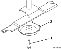
-
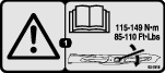
Install the blade-sail facing toward the cutting unit-with the anti-scalp cup and blade bolt. Tighten the blade bolt to 115 to 149 N∙m (85 to 110 ft-lb).
Important: The curved part of the blade must point toward the inside of the cutting unit to ensure proper cutting.
Inspecting and Sharpening the Blade(s)
| Maintenance Service Interval | Maintenance Procedure |
|---|---|
| After the first 10 hours |
|
| Before each use or daily |
|
| Every 50 hours |
|
Danger
A worn or damaged blade can break, and a piece of the blade could be thrown toward you or bystanders, resulting in serious personal injury or death.
-
Inspect the blade periodically for wear or damage.
-
Do not try to straighten a blade that is bent.
-
Do not weld a broken or cracked blade.
-
Replace a worn or damaged blade with a new Toro blade to ensure continued safety certification of the product.
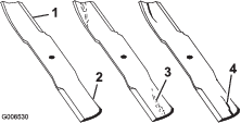
Both cutting edges and the sail, which is the turned up portion opposite the cutting edge, contribute to a good quality-of-cut. The sail is important because it pulls grass up straight, thereby producing an even cut. However, the sail will gradually wear down during operation, and this condition is normal. As the sail wears down, the quality-of-cut will degrade somewhat, although the cutting edges are sharp. The cutting edge of the blade must be sharp so that the grass is cut rather than torn. A dull cutting edge is evident when the tips of the grass appear brown and shredded. Sharpen the cutting edges to correct this condition.
-
Park the machine on a level surface. Raise the cutting unit, engage the parking brake, put the traction pedal in neutral, put the PTO lever in the OFF position, shut off the engine, and remove the key.
-
Examine the cutting ends of the blade carefully, especially where the flat and curved parts of the blade meet (Figure 32). Since sand and abrasive material can wear away the metal that connects the flat and curved parts of the blade, check the blade before using the machine. If you see wear (Figure 32), replace the blade; refer to Removing and Installing the Blade(s).
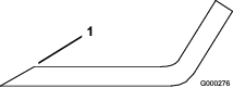
Warning
If the blade is allowed to wear, a slot will form between the sail and flat part of the blade (Figure 32). Eventually, a piece of the blade may break off and be thrown from under the housing, possibly resulting in serious injury to yourself or bystanders.
-
Inspect the blade periodically for wear or damage.
-
Replace a worn or damaged blade with a new Toro blade to ensure continued safety certification of the product.
-
-
Examine the cutting edges of all blades. Sharpen the cutting edges if they are dull or nicked. Sharpen only the top side of the cutting edge and maintain the original cutting angle to ensure sharpness (Figure 33). The blade will remain balanced if the same amount of metal is removed from both cutting edges.
Note: Remove the blades and sharpen them on a grinder; refer to Removing the Cutting Blades. After sharpening the cutting edges, install the blade with the anti-scalp cup and blade bolt. The blade sails must be on top of the blade. Tighten the blade bolt to 115 to 149 N·m (85 to 110 ft-lb).
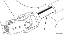
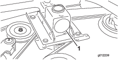
Replacing the Drive Belt
| Maintenance Service Interval | Maintenance Procedure |
|---|---|
| Every 50 hours |
|
The blade drive belt, tensioned by the spring loaded idler pulley, is very durable. However, after many hours of use, the belt will show signs of wear. Signs of a worn belt are squealing when belt is rotating, blades slipping when cutting grass, frayed edges, burn marks, and cracks. Replace the belt if any of these conditions occur.
-
Lower the cutting unit to the shop floor. Remove the belt covers from the top of the cutting unit and set the covers aside.
-
Using a torque wrench or similar tool, move the idler pulley (Figure 34) away from the drive belt to release the belt tension and allow the belt to be slipped off the gearbox pulley (Figure 35).
-
Remove the old belt from around the spindle pulleys and idler pulley.
-
Route the new belt around the spindle pulleys and idler pulley assembly as shown in Figure 36.
-
Install the belt covers.
Replacing the Grass Deflector
Warning
An uncovered discharge opening could allow the machine to throw objects toward you or bystanders, resulting in serious injury. Also, contact with the blade could occur.
-
Do not operate the machine unless you install a cover plate, a mulch plate, or a grass chute and catcher.
-
Ensure that the grass deflector is in the down position.
-
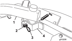
Remove the locknut, bolt, spring and spacer holding the deflector to the pivot brackets (Figure 37). Remove the damaged or worn grass deflector.
-
Place the spacer and spring onto grass deflector. Place the L end of spring behind deck edge.
Note: Ebsure that the L-end of the spring is installed behind the deck edge before installing the bolt as shown in Figure 37.
-
Install the bolt and nut. Place the J-hook end of the spring around the grass deflector (Figure 37).
Important: You must be able to lower the grass deflector into position. Lift the deflector up to test that it lowers into the full down position.