


Maintenance
Note: Determine the left and right sides of the machine from the normal operating position.
Note: Looking for an Electrical Schematic or Hydraulic Schematic for your machine? Download a free copy of the schematic by visiting www.Toro.com and searching for your machine from the Manuals link on the home page.
Caution
If you leave the key in the ignition switch, someone could accidently start the engine and seriously injure you or other bystanders.
Remove the key from the ignition.
Recommended Maintenance Schedule(s)
| Maintenance Service Interval | Maintenance Procedure |
|---|---|
| After the first operating hour |
|
| After the first 8 operating hours |
|
| After the first 50 operating hours |
|
| Before each use or daily |
|
| Every 25 hours |
|
| Every 50 hours |
|
| Every 150 hours |
|
| Every 200 hours |
|
| Every 400 hours |
|
| Every 800 hours |
|
| Every 2 years |
|
Important: Refer to your engine operator’s manual for additional maintenance procedures.
Lubrication
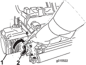
Greasing the Generator Belt Tensioner
Lubricate the grease fitting regularly with No. 2 lithium grease.
-
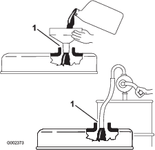
Wipe the grease fitting clean so that foreign matter cannot be forced into the bearing or bushing (Figure 44).
-
Pump grease into the bearing or bushing until the grease is visible. Wipe up excess grease.
Engine Maintenance
Servicing the Air Cleaner
-
Check the air-cleaner body for damage which could cause an air leak. Replace if damaged. Check the whole intake system for leaks, damage or loose hose clamps.
-
Service the air-cleaner filter before 200 hours if the engine performance suffers due to extremely dusty, dirty conditions. Changing the air filter before it is necessary only increases the chance of dirt entering the engine when the filter is removed.
-
Be sure the cover is seated correctly and seals with the air cleaner body.
-
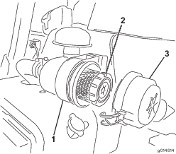
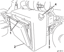
Release the latches securing the air cleaner cover to the air cleaner body (Figure 45).
-
Remove the cover from the air-cleaner body. Before removing the filter, use low pressure air (40 psi, clean and dry) to help remove large accumulations of debris packed between outside of primary filter and the canister. Avoid using high pressure air which could force dirt through the filter into the intake tract. This cleaning process prevents debris from migrating into the intake when the primary filter is removed.
-
Remove and replace the primary filter. Cleaning of the used element is not recommended due to the possibility of damage to the filter media. Inspect the new filter for shipping damage, checking the sealing end of the filter and the body. Do not use a damaged element. Insert the new filter by applying pressure to the outer rim of the element to seat it in the canister. Do not apply pressure to the flexible center of the filter.
-
Clean the dirt ejection port located in the removable cover. Remove the rubber outlet valve from the cover, clean the cavity and replace the outlet valve.
-
Install the cover orienting the rubber outlet valve in a downward position—between approximately 5:00 to 7:00 when viewed from the end.
-
Secure the latches (Figure 45).
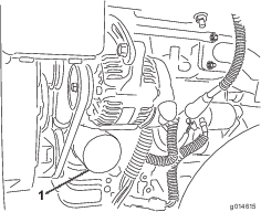
Changing the Engine Oil and Filter
-
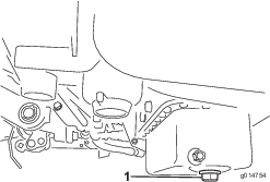
Remove the drain plug and let oil flow into a drain pan. When the oil stops, install the drain plug (Figure 46).
-
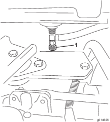
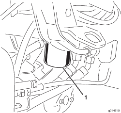
Remove the oil filter (Figure 47). Apply a light coat of clean oil to the new filter gasket.
-
Screw the filter on by hand until the gasket contacts the filter adapter, then tighten 1/2 to 3/4 turn further. Do not overtighten.
-
Add oil to the crankcase; refer to Checking the Engine Oil.
-
Dispose of the used oil properly.
Fuel System Maintenance
Servicing the Fuel Filter/Water Separator
Servicing the Fuel Filter
-
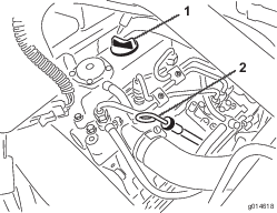
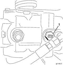
Close the fuel-shutoff valve (Figure 48) below the fuel tank.
-
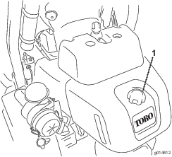
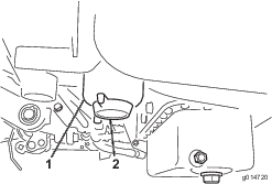
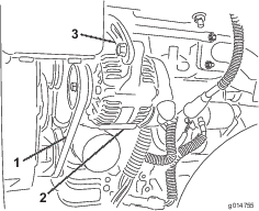
Clean the area where the filter canister mounts (Figure 49).
-
Place a drain pan under the fuel filter.
-
Open the filter-drain plug (Figure 49).
-
Unscrew the filter canister and dispose of it according to local regulations.
-
Screw the filter on by hand until the gasket contacts the filter adapter, then tighten 1/2 to 3/4 turn further.
-
Make sure the filter-drain plug is closed. Open the fuel-shutoff valve.
Inspecting the Fuel Lines and Connections
Inspect the fuel lines for deterioration, damage, or loose connections.
Close sectionElectrical System Maintenance
Servicing the Battery
Warning
CALIFORNIA
Proposition 65 Warning
Battery posts, terminals, and related accessories contain lead and lead compounds, chemicals known to the State of California to cause cancer and reproductive harm. Wash hands after handling.
Voltage: 12 V, 530 Cold Cranking Amps
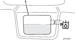
The battery electrolyte level must be properly maintained and the top of the battery kept clean. lf the machine is stored in a location where temperatures are extremely high, the battery will run down more rapidly than if the machine is stored in a location where temperatures are cool.
Maintain the cell level with distilled or demineralized water. Do not fill the cells above the bottom of the split ring inside each cell.
Danger
Battery electrolyte contains sulfuric acid which is a deadly poison and causes severe burns.
-
Do not drink electrolyte and avoid contact with skin, eyes or clothing. Wear safety glasses to shield your eyes and rubber gloves to protect your hands.
-
Fill the battery where clean water is always available for flushing the skin.
Keep the top of the battery clean by washing it periodically with a brush dipped in ammonia or bicarbonate of soda solution. Flush the top surface with water after cleaning it. Do not remove the fill caps while cleaning the battery.
The battery cables must be tight on the terminals to provide good electrical contact.
Warning
Battery terminals or metal tools could short against metal tractor components causing sparks. Sparks can cause the battery gasses to explode, resulting in personal injury.
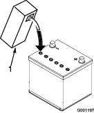
-
When removing or installing the battery, do not allow the battery terminals to touch any metal parts of the tractor.
-
Do not allow metal tools to short between the battery terminals and metal parts of the tractor.
Warning
Incorrect battery cable routing could damage the tractor and cables causing sparks. Sparks can cause the battery gasses to explode, resulting in personal injury.
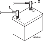
If corrosion occurs at the terminals, disconnect the cables, negative (-) cable first, and scrape the clamps and terminals separately. Reconnect the cables, positive (+) cable first, and coat the terminals with petroleum jelly.
-
Always disconnect the negative (black) battery cable before disconnecting the positive (red) cable.
-
Always connect the positive (red) battery cable before connecting the negative (black) cable.
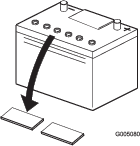
Storing the Battery
If the machine will be stored more than 30 days, remove the battery and charge it fully. Either store it on the shelf or on the machine. Leave the cables disconnected if it is stored on the machine. Store the battery in a cool atmosphere to avoid quick deterioration of the charge in the battery. To prevent the battery from freezing, make sure it is fully charged. The specific gravity of a fully charged battery is 1.265–1.299.
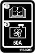
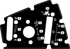
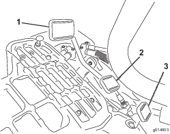
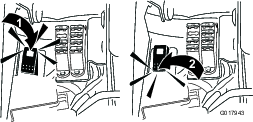
Close sectionLocating the Fuses
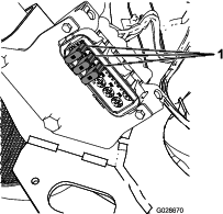
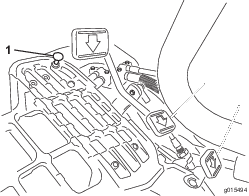
The fuses are located under the seat (Figure 50) and under the right arm cover (Figure 51).
| Fuse Layout | |
| Lift Reel | |
| Starter | E-Reel Enable |
| Over Temp | |
| 10 A | 7.5 A |
| Reel Engage | |
| Run | Lift/Lower |
| Fan | |
| 10 A | 7.5 A |
| Start/Run | |
| Lights | Diag. Lights |
| Leak Detector | Glow |
| 15 A | 7.5 A |
| ECM Logic | |
| Power | |
| 2 A |
| Fuse Layout |
| 35 A |
| 35 A |
| 35 A |
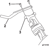
Jump Starting the Machine
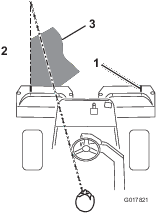
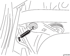
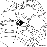
If the machine needs to be jump started, the alternate positive post (located on the starter solenoid) can be used instead of the positive battery post (Figure 52).
Drive System Maintenance
Adjusting the Transmission for Neutral
If the machine creeps when the traction control pedal is in the neutral position, the neutral return mechanism must be adjusted.
-
Block up under the frame so that one of the front wheels is off of the floor.
Note: Note: If machine is equipped with a 3 wheel drive kit, also raise and block rear wheel.
-
Start the engine, move the throttle to Slow, and check the front wheel that is off of the floor; it must not be rotating.
-
If the wheel is rotating, stop the engine and proceed as follows:
-
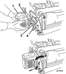
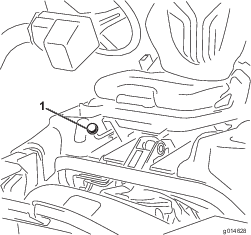
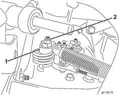
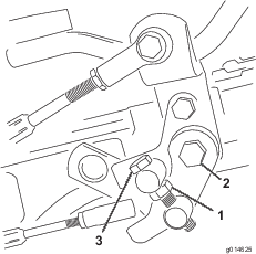
Loosen the nut securing the eccentric to the top of the hydrostat (Figure 53).
-
Move the functional control lever to Neutral and the throttle to Slow. Start the engine.
-
Rotate the eccentric until creep does not occur in either direction. When the wheel stops rotating, tighten the nut locking the eccentric and the adjustment (Figure 53). Verify the adjustment with the throttle in the Slow and Fast position.
Note: If the wheel still turns when the eccentric is at the maximum adjustment, contact your Authorized Service Distributor or refer to the Service Manual for further adjustment.
-
Adjusting the Transport Speed
The traction pedal is adjusted for maximum transport speed at the factory, but an adjustment may be required if the pedal reaches full stroke before it contacts the pedal stop, or if a decrease in transport speed is desired.
Press down on the traction pedal. If the pedal contacts the stop (Figure 54) before tension is felt on the cable, an adjustment is required:
-
Loosen flangehead locknuts securing the pedal stop to the floor plate (Figure 54).
-
Adjust the pedal stop so it contacts the pedal rod and tighten the nuts.
Adjusting the Mowing Speed
The mow speed is set to 3.8 mph at the factory.
The forward moving speed can be adjusted from 0 to 8 km/h (0 to 5 mph).
-
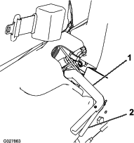
Loosen the jam nut on the trunnion bolt (Figure 55).
-
Loosen the nut securing the lock and mow brackets on the pedal pivot.
-
Rotate the trunnion bolt clockwise to reduce the mowing speed and counterclockwise to increase the mowing speed.
-
Tighten the jam nut on the trunnion bolt and the nut on the pedal pivot to lock the adjustment (Figure 55). Check the adjustment and adjust as required.
Cooling System Maintenance
Cleaning the Radiator Screen
To prevent the system from overheating, the radiator screen and radiator must be kept clean. Check and clean the screen and radiator daily or, if necessary, hourly. Clean these components more frequently in dusty, dirty conditions.
-
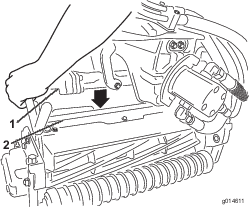
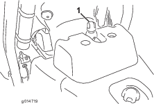
Remove the radiator screen (Figure 56).
-
Working from the fan side of the radiator, blow out the radiator with compressed air.
-
Clean the screen and install it.
Brake Maintenance
Adjusting the Brakes
If the brake fails to hold the machine while parked, you can adjust the brakes using the bulkhead fitting near the brake drum; contact your Authorized Service Distributor or refer to the Service Manual for more information.
Close sectionBelt Maintenance
Adjusting the Alternator Belt
Make sure the belt is properly tensioned to ensure proper operation of the machine and prevent unnecessary wear.
-
Stop the engine, set the parking brake, and remove the ignition key.
-
Apply moderate thumb pressure to the belt between the pulleys (10 kg or 22 lb). The belt should deflect 7 to 9 mm (0.28 to 0.35 inches). If not, complete the following procedure to adjust the belt tension:
-
Loosen the bolts securing the alternator to the engine and adjusting strap.
-
Inspect the belt for wear or damage and replace if it is worn.
-
Using a lever placed between the alternator and the engine block, pull the alternator out to obtain the correct belt tension and tighten the bolts.
-
Hydraulic System Maintenance
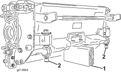
Changing the Hydraulic Oil and Filter
If the oil becomes contaminated, contact your local Toro distributor because the system must be flushed. Contaminated oil looks milky or black when compared to clean oil.
-
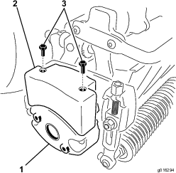
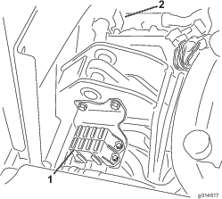
Clean the area around the filter mounting area (Figure 58). Place a drain pan under the filter and remove the filter.
Note: If the oil is not going to be drained, disconnect and plug the hydraulic line going to the filter.
-
Fill the replacement filter with the appropriate hydraulic fluid, lubricate the sealing gasket, and hand turn it until the gasket contacts the filter head. Then tighten 3/4 turn further. The filter should now be sealed.
-
Fill the hydraulic reservoir with hydraulic oil; refer to Filling the Hydraulic Tank.
-
Start the machine and run it at idle for 3 to 5 minutes to circulate the fluid and remove any air trapped in the system.
-
Stop the machine, recheck the fluid level and replenish as required.
-
Dispose of the oil and filter properly.
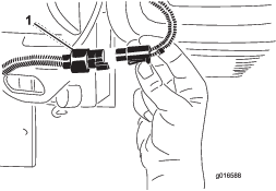
Checking the Hydraulic Lines and Hoses
Warning
Hydraulic fluid escaping under pressure can penetrate skin and cause injury.
-
Make sure all hydraulic fluid hoses and lines are in good condition and all hydraulic connections and fittings are tight before applying pressure to the hydraulic system.
-
Keep your body and hands away from pin hole leaks or nozzles that eject high pressure hydraulic fluid.
-
Use cardboard or paper to find hydraulic leaks.
-
Safely relieve all pressure in the hydraulic system before performing any work on the hydraulic system.
-
Get immediate medical help if fluid is injected into skin.
Check the hydraulic lines and hoses daily for leaks, kinked lines, loose mounting supports, wear, loose fittings, weather deterioration, and chemical deterioration. Make all necessary repairs before operating.
Close sectionBacklapping the Reels
Warning
Contact with the reels or other moving parts can result in personal injury.
-
Keep fingers, hands, and clothing away from the reels or other moving parts.
-
Never attempt to turn the reels by hand or foot while the engine is running.
-
Position the machine on a level surface, lower the cutting units, stop the engine, engage the parking brake.
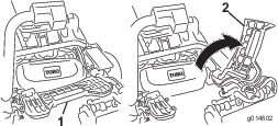
-
Remove the plastic cover to the left side of the seat.
-
Make initial reel to bedknife adjustments appropriate for backlapping on all cutting units which are to be backlapped; refer to the Cutting Unit Operator’s Manual.
-
Start the engine and run at low idle speed. If the engine stalls, increase the engine speed.
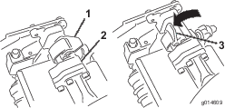
-
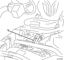
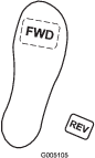
Switch the Backlap Switch to the reverse (R) position (Figure 59).
-
On the InfoCenter pull up the Main Menu and scroll down to Settings.
-
In the Settings menu scroll down to Backlap rpm and use the button to select the desired backlap speed.
-
With the functional control lever in the neutral position, move the Raise/Lower Mow control forward to start the backlapping operation on the designated reels.
-
Apply lapping compound with a long handle brush. Never use a short handled brush.
-
If the reels stall or become erratic while backlapping, select a higher reel speed setting until the speed stabilizes.
-
To make an adjustment to the cutting units while backlapping, turn the reels off by moving the Raise/Lower Mow control rearward and stop the engine. After completing adjustments, repeat steps 4 through 9.
-
Repeat the procedure for all cutting units you want to backlap.
-
When finished, return the backlap switch to the forward (F) position, replace the cover, and wash all lapping compound off of the cutting units. Adjust cutting unit reel to bedknife as needed. Move the cutting unit reel speed control to the desired mowing position.
Important: If the backlap switch is not returned to the forward (F) position after backlapping, the cutting units will not raise or function properly.