| Maintenance Service Interval | Maintenance Procedure |
|---|---|
| Before each use or daily |
|
Introduction
This machine is a walk-behind, reel-blade lawn mower intended to be used by professional, hired operators in commercial applications. It is primarily designed for cutting grass on well-maintained lawns in parks, golf courses, sports fields, and on commercial grounds. It is not designed for cutting brush, mowing grass and other growth alongside highways, or for agricultural uses.
Important: To maximize the safety, performance, and proper operation of this machine, carefully read and fully understand the contents of this Operator’s Manual. Failing to follow these operating instructions or to receive proper training may result in injury. For more information on safe operating practices, including safety tips and training materials, go to www.Toro.com.
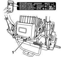
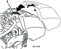
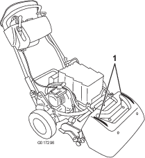
Whenever you need service, genuine Toro parts, or additional information, contact an authorized Toro distributor and have the model and serial numbers of your product ready. Figure 1 identifies the location of the model and serial numbers on the machine, and the location of the model number, serial number, and the manufacturer’s information on the battery. Write the numbers in the space provided.
Important: With your mobile device, you can scan the QR code (if equipped) on the serial number decal to access warranty, parts, and other product information.
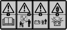
This manual identifies potential hazards and has safety messages identified by the safety-alert symbol (Figure 2), which signals a hazard that may cause serious injury or death if you do not follow the recommended precautions.

This manual uses 2 words to highlight information. Important calls attention to special mechanical information and Note emphasizes general information worthy of special attention.
This product complies with all relevant European directives; for details, please see the separate product specific Declaration of Conformity (DOC) sheet.
Warning
CALIFORNIA
Proposition 65 Warning
Use of this product may cause exposure to chemicals known to the State of California to cause cancer, birth defects, or other reproductive harm.
Safety
This machine has been designed in accordance with EN ISO 5395:2013 and ANSI B71.4-2017 and meets these standards when you add the Operator Presence kit.
General Safety
This product is capable of amputating hands and feet and of throwing objects. Always follow all safety instructions to avoid serious personal injury.
Using this product for purposes other than its intended use could prove dangerous to you and bystanders.
-
Read and understand the contents of this Operator’s Manual before starting the machine.
-
Do not put your hands or feet near moving components of the machine.
-
Do not operate the machine without all guards and other safety protective devices in place and working on the machine.
-
Keep clear of any discharge opening. Keep bystanders a safe distance away from the machine.
-
Keep children out of the operating area. Never allow children to operate the machine.
-
Shut off the machine and disconnect the battery before servicing or unclogging the machine.
Improperly using or maintaining this machine can result in injury. To reduce the potential for injury, comply with these safety instructions and always pay attention to the safety-alert symbol, which means Caution, Warning, or Danger—personal safety instruction. Failure to comply with these instructions may result in personal injury or death.
You can find additional safety information where needed throughout this manual.
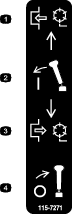
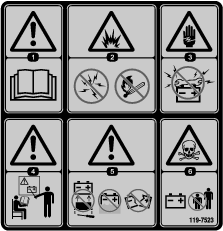
Safety and Instructional Decals
|
Safety decals and instructions are easily visible to the operator and are located near any area of potential danger. Replace any decal that is damaged or missing. |


Setup
Note: Determine the left and right sides of the machine from the normal operating position.
Note: To install the weight rod onto your machine, refer to the installation instructions in your cutting unit Operator’s Manual.
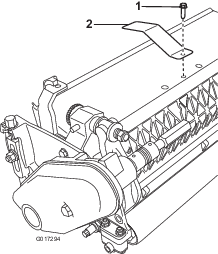
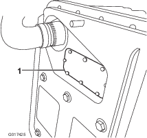
Installing the Target Plate
Preparing the Traction Unit
Optional—Cutting Unit Models 04251, 02452, 04253,
or 04254
If you are installing cutting unit Models 04251, 02452, 04253, or 04254 on this traction unit, complete the following steps:
Installing the Cutting Unit to the Traction Unit
Parts needed for this procedure:
| Bolt (3/8 x 3/4 inch) | 2 |
Note: To install the weight rod onto your machine, refer to the installation instructions in your cutting unit Operator’s Manual.
-
Place the mower on its drums on a level surface.
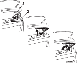
-
Lower the kickstand and push in the locking pin to lock the kickstand in the SERVICE position (Figure 6). Allow the machine to rest on the locked kickstand.
Note: Place the kickstand in the SERVICE position whenever you remove the cutting unit. This kickstand position keeps the machine from tipping backward onto the handle.
-
Push the cutting unit under the traction unit and to the left to engage the transmission coupling (Figure 7).
-
Maneuver the machine frame forward until it engages the cutting unit pivot arms Figure 8.
-
Secure the machine frame to the cutting unit pivot arms with the 2 bolts (3/8 x 3/4 inch) (Figure 8).
-
Move the kickstand to the STORAGE position by releasing the locking pin and allowing the kickstand to rotate up.
-
Set the cutting-unit height of cut; refer to your cutting unit Operator’s Manual.
Installing the Handle Retainers
Parts needed for this procedure:
| Handle retainer | 2 |
| Hairpin cotter | 2 |
-
While supporting the handle, remove the cable ties that secure the handle clamps to the side plates (Figure 9).
-
Pivot the handle to the desired operating position and insert a handle retainer over the handle clamp and into the matching holes in the side plate (Figure 9).
-
Secure the clamp in position with a hairpin cotter (Figure 9).
-
Repeat the procedure on the opposite side of the handle.
-
Adjust the handle height to the desired position; refer to Adjusting the Handle Height.
Note: The machine is shipped with the handle adjusted to the lowest position. The machine is traditionally operated with the handle telescoped out to its maximum height.
Installing the Battery Pack
Parts needed for this procedure:
| Battery pack | 1 |
| Bolt (5/16 x 1/2 inch) | 6 |
| Washer | 6 |
-
Remove the battery pack from its carton.
Save the carton and all packing materials. If you need to ship the battery for maintenance, warranty, or recycling, you will need this special packaging.
Refer to the Installation Instructions included with the Battery Shipping Kit (the instructions can be found at www.Toro.com).
-
Cut the cable tie that secures the battery charger to the battery base on the machine and remove the charger.
-
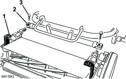
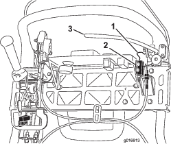
Disconnect the small connector on the pack to the machine wire harness from the main wire harness (Figure 10).
-
Remove the tall nut that secures the rear of the battery base to the machine frame (Figure 11).
-
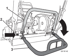
Loosen the 2 pivot bolts/nuts a half turn each (Figure 12).
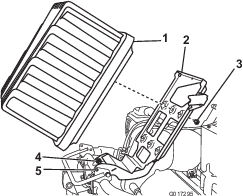
-
Raise the battery platform until the locking holes in the base and frame align (Figure 12).
Note: Slide a screwdriver or other steel rod through the holes to hold the platform in the raised position.
-
Place the battery pack on the base with the connector port toward the rear of the machine.
-
Secure the battery pack to the base with the 6 bolts (5/16 x 1/2 inch) and 6 washers.
Note: Torque each bolt to 11.3 to 14 N∙m (100 to 130 in-lb).
-
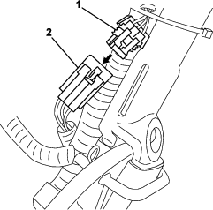
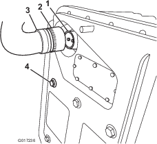
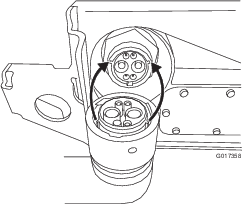
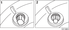
Line up the tabs on the inside of the harness power plug with the slots in the battery pack receptacle.
Note: Press the harness connector into the battery connector (Figure 13 and Figure 14).
-
Rotate the locking collar on the harness plug clockwise until it engages with the battery receptacle and begins to pull in toward the battery.
Note: Continue turning it another 120° (1/3 of a turn) until it fully seats.
Note: If you cannot mate the battery pack receptacle with the machine wire harness plug while the battery pack is installed, you can instead connect the harness to the battery pack and then install the battery pack. Remove the main power supply connector (Figure 16) from the battery base. Install the connector to the battery as described. Install the battery to the base, threading the attached wire harness through the appropriate hole, and then secure the main power supply connector to the battery base with the fasteners that you previously removed.
-
Remove the screwdriver holding the battery base in the up position, and gently lower the battery platform to the machine frame.
Important: Do not pinch the wire harness between the frame and platform.
-
Secure the battery platform to the machine frame with the tall nut removed in step 4.
-
Tighten the pivot fasteners loosened in step 5.
-
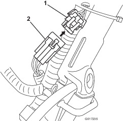
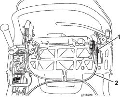
Route the pack to machine wire harness under and behind the main harness on the left side of the machine and connect the small 6-pin connector on the harness to the matching connector on the main wire harness as shown in Figure 15.
-
Turn on and turn off the machine to ensure that the battery charges completely.
-
Connect the T-handle connector from the main wire harness to the main power supply connector on the battery base (Figure 16).

-
Charge the battery; refer to the lithium battery charger Operator’s Manual.
Note: The battery is shipped with a partial charge (approximately 40%). This is enough charge for you to perform functional checks on the machine and move it as necessary to complete setup, but you should fully charge the battery before you use the machine.
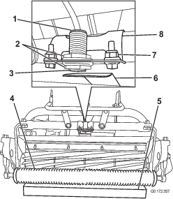
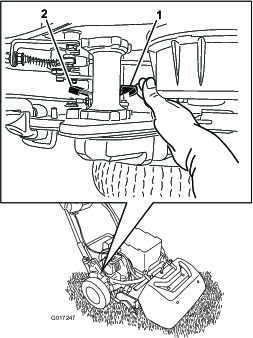
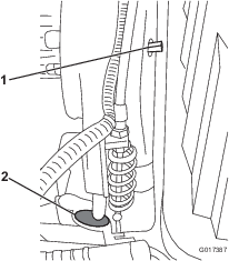
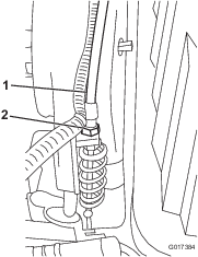
Adjusting the EZ-Turn Sensor
-
Ensure that the machine is on a flat, level surface with the traction drum on the ground.
-
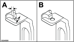
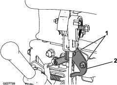
Loosen the jam nuts on the sensor and adjust the sensor so that 1 thread is visible past the lower jam nut (Figure 17).
-
Tighten the jam nuts to secure the sensor.
-
Place a 3.8 cm (1-1/2 inches) block under the front cutting unit roller (Figure 17).
-
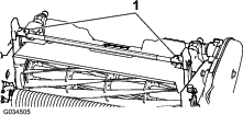
Loosen the fasteners that secure the sensor bracket to the frame (Figure 17).
-
Start the machine; refer to Starting the Machine.
-
Set the EZ-Turn switch to the ON position.
-
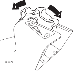
Rotate the sensor bracket toward the target plate until the light on top of the sensor illuminates (Figure 17). If the light was already illuminated, rotate it away from the target plate until it goes out and then reverse direction until it illuminates again.
-
Tighten the bracket fasteners.
-
Remove the block from under the roller and place the machine on the kickstand.
-
Ensure that the target plate does not contact the grass shield.
Note: If the plate does contact the shield, loosen the bracket fasteners and rotate the switch up until the plate is no longer touching the shield.
-
Turn off the machine.
Installing the Transport Wheels
Optional
Parts needed for this procedure:
| Transport wheels—Transport Wheel Kit (Model No. 04123 [Optional]) | 2 |
-
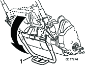
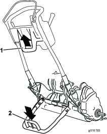
Use your foot to push the center of the kickstand down and pull up on the lower handle support until the kickstand has rotated forward and over center (Figure 18).
-
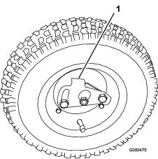
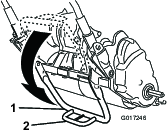
Press the wheel locking clip toward the center of wheel and slide the wheel onto the hex shaft (Figure 19).
-
Rotate the wheel back and forth until it fits onto the axle and the locking clip is secured in the groove on the axle shaft.
-
Repeat the procedure on the opposite side of the machine.
-
Inflate the tires to 83 to 103 kPa (12 to 15 psi).
-
Carefully lower the machine off of the kickstand by pushing forward slowly or by lifting the lower handle support, allowing the kickstand to spring back to the STORAGE position.
Installing the Production-Year Decal
CE Machines Only
Parts needed for this procedure:
| Production-year decal | 1 |
If you use this machine in a country that complies to CE standards, apply the production-year decal near the serial plate; refer to Figure 20.
Installing the Grass Basket
Parts needed for this procedure:
| Grass basket | 1 |
-
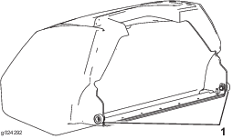
Grasp the basket by the handle.
-
Guide the basket lip between the cutting unit side plates and over the front roller (Figure 21).
-
Install the basket hooks over the frame loop (Figure 21).
Important: If you ever drop the basket, examine the pitch-arm contact points near the lower lip of the basket for damage (Figure 22). Straighten them before using the basket.Using the basket with bent pitch-arm contact points may cause contact between the basket and cutting unit, causing undesired noise and/or damage to the basket and cutting unit.
Breaking in the Machine
Only 8 hours of mowing operation is required for the break-in period.
Since the first hours of operation are critical to future dependability of the machine, monitor the machine functions and performance closely so that minor difficulties, which could lead to major problems, are noted and can be corrected. Inspect the machine frequently during break-in for signs of loose fasteners or any other malfunction.
Product Overview
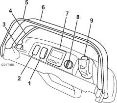
EZ-Turn Switch
The EZ-Turn switch (Figure 24) enables or disables the EZ-Turn feature. The EZ-Turn feature automatically slows the machine whenever you raise the cutting unit off the ground during mowing. This allows you to make the turns at the end of each mowing pass at a slower speed. You can use the switch at any time, even while mowing.
This feature only reduces the ground speed when the reel is engaged and lifted off the ground. It has no effect on ground speed when the reel is disengaged. If this feature is activated while mowing and you turn off the reel, the machine will speed up. If you are mowing at a slow speed already, the EZ-Turn feature will not slow the machine on a turn.
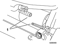
Service Brake
The service brake (Figure 25) is located on the left front side of the handle. Pulling back the lever applies the service brake.
You must disengage the brake before you engage the traction drive. If you operate the machine with the brake engaged, the machine moves, but with a high resistance and increased power consumption.
Parking-Brake Latch
Use the parking-brake latch (Figure 25) with the service brake. Rotate the parking-brake latch toward the brake handle to hold the service brake in place. Pull the brake lever to release.
Note: The traction-control lever cannot be moved while the latch is engaged.
Operator-Presence Control (OPC)
You must engage the operator-presence control (Figure 24) before you engage the traction lever. If you release the OPC during operation, the traction lever returns to neutral and the engine continues to run.
InfoCenter LCD Display
The InfoCenter LCD display shows information about your machine and battery pack, such as the current battery charge, speed, diagnostics information, and more (Figure 24).
For more information, refer to Using the InfoCenter LCD Display.
Key Switch
The key switch (Figure 24) has 3 positions: OFF, RUN, and START. With the brake off and the traction drive disengaged, move the switch to the START position until the InfoCenter display lights up, then release it to the RUN position. Turn it to the OFF position and remove the key to turn off the machine.
Speed Control
Traction and Reel-Drive Engagement Lever
The traction and reel-drive engagement lever (Figure 27) is located on the front right side of the control panel.
To transport the machine, the lever has 2 positions: NEUTRAL and FORWARD. Pushing the lever to the traction—FORWARD (transport) position or the traction—FORWARD and reel drive—ENGAGE position engages the traction drive (Figure 27).
Note: To move the lever, you must first engage the operator-presence control.
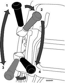
To operate the reel, the lever has 2 positions: ENGAGE and DISENGAGE. Move the top of the lever to the left, then forward to the traction—FORWARD and reel drive—ENGAGE position to engage the reel and begin mowing. Push the lever to the right to the traction—FORWARD (transport) position to disengage the reel and continue forward motion or pull back on it to the traction—NEUTRAL and reel drive—DISENGAGE position to disengage both the reel and the traction drive (Figure 27).
Note: If you release the operator-presence control, the lever returns to neutral and the machine stops.
Automatic-Motor Brake
The machine is equipped with an automatic-motor brake that prevents it from rolling when the machine is shut off. The motor brake is on whenever the traction drive is in the NEUTRAL position or you move the speed control to the ZERO position, except in the following circumstances:
-
When the machine is turned off, use the parking-brake latch to ensure that the service brake is consistently engaged.
-
When you start the machine with the key switch, the motor brake is initially disengaged. After driving the machine, the motor brake functions normally.
-
If you move the speed control to zero speed while the reels are engaged (i.e., while mowing), the brake does not engage. This feature allows you to move to the speed control to the ZERO position while mowing and pull the machine rearward to make course corrections.
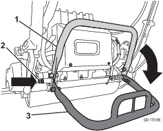
Kickstand
The kickstand (Figure 29) is mounted to the rear of the machine. Use the kickstand when you install or remove the transport wheels or the cutting unit.
-
To use the kickstand to install the transport wheels, lower the kickstand to the ground and step down on the loop while pulling up and back on the lower-center handle (Figure 28).
Caution
The machine is heavy and can cause back strain if lifted improperly.
Put your foot pressure down on the kickstand loop and use only the lower-center handle to raise the machine. Attempting to raise the machine onto the kickstand any other way can cause injury.
-
To prevent the machine from tipping backward when removing the reel, lower the kickstand and push in the locking pin to lock it in the SERVICE position (Figure 30).
| Width | 82.5 cm (32.5 inches) |
| Height | 104.8 cm (41.3 inches) |
| Length with basket | 152.4 cm (60 inches) |
| Net Weight (with 11 blade cutting unit and grass basket installed) | 129.3 kg (285 lb) |
| Width of cut | 46 cm (18 inches) |
| Height of cut | 1.5 to 7.5 mm (1/16 to 19/64 inches) with Micro-Cut bedknife |
| Clip frequency | Adjustable (Refer to Cutting Unit Operator’s Manual) |
| Width | 90.1 cm (35.5 inches) |
| Height | 104.8 cm (41.3 inches) |
| Length with basket | 152.4 cm (60 inches) |
| Net Weight (with 11 blade cutting unit and grass basket installed) | 132.9 kg (293 lb) |
| Width of cut | 53.3 cm (21 inches) |
| Height of cut | 1.5 to 7.5 mm (1/16 to 19/64 inches) with Micro-Cut bedknife |
| Clip frequency | Adjustable (Refer to the Cutting Unit Operator’s Manual) |
Attachments/Accessories
A selection of Toro approved attachments and accessories is available for use with the machine to enhance and expand its capabilities. Contact your Authorized Service Dealer or Distributor.
To best protect your investment and maintain optimal performance of your Toro equipment, count on Toro genuine parts. When it comes to reliability, Toro delivers replacement parts designed to the exact engineering specification of our equipment. For peace of mind, insist on Toro genuine parts.
Operation
Before Operation
Before Operation Safety
General Safety
-
Never allow children or untrained people to operate or service the machine. Local regulations may restrict the age of the operator. The owner is responsible for training all operators and mechanics.
-
Become familiar with the safe operation of the equipment, operator controls, and safety signs. Know how to shut off the machine quickly.
-
Check that operator-presence controls, safety switches, and shields are attached and functioning properly. Do not operate the machine unless they are functioning properly.
-
Inspect the area where you will use the machine, and remove all objects that could interfere with the operation of the machine or that the machine could throw.
-
Evaluate the terrain to determine what accessories and attachments are needed to properly and safely perform the job.
Performing Daily Maintenance
Perform the daily maintenance procedures; refer to Daily Maintenance Checklist.
Setting the Machine to Match Turf Conditions
Use the following table to set the machine to match turf conditions.
| Bedbars: Standard and Optional (Flex/eFlex 2120 Machines) | |||
| Part Number | Description | Aggressiveness | Comments |
| 106-2468-01 | Non-Aggressive | Less | Red, Standard |
| 99-3794-03 | Aggressive | More | Black |
| Bedbars: Standard and Optional (Flex/eFlex 1820 Machines) | |||
| 110-2282-01 | Non-Aggressive | Less | Red, Standard |
| 110-2281-03 | Aggressive | More | Black |
| Bedknives: Standard and Optional (Flex/eFlex 2120 Machines) | |||
| Part Number | Description | Height-of-cut Range | Comments |
| 115-1880 | Microcut-EdgeMax | 1.6 to 3.2 mm (0.062 to 0.125 inch) | Standard |
| 93-4262 | Microcut | 1.6 to 3.2 mm (0.062 to 0.125 inch) | |
| 108-4303 | Extended Microcut | 1.6 to 3.2 mm (0.062 to 0.125 inch) | Less aggressive |
| 115-1881 | Tournament- EdgeMax | 3.2 to 6.4 mm (0.125 to 0.25 inch) | |
| 93-4263 | Tournament | 3.2 to 6.4 mm (0.125 to 0.25 inch) | |
| 108-4302 | Extended Tournament | 3.2 to 6.4 mm (0.125 to 0.25 inch) | Less aggressive |
| 93-4264 | Low Cut | 6.4 mm (0.25 inch) and up | |
| Bedknives: Standard and Optional (Flex/eFlex 1820 Machines) | |||
| 117-1530 | Microcut-EdgeMax | 1.6 to 3.2 mm (0.062 to 0.125 inch) | Standard |
| 98-7261 | Microcut | 1.6 to 3.2 mm (0.062 to 0.125 inch) | |
| 110-2300 | Extended Microcut | 1.6 to 3.2 mm (0.062 to 0.125 inch) | Less aggressive |
| 98-7260 | Tournament | 3.2 to 6.4 mm (0.125 to 0.25 inch) | |
| 117-1532 | Tournament- EdgeMax | 3.2 to 6.4 mm (0.125 to 0.25 inch) | |
| 110-2301 | Low Cut | 6.4 mm (0.25 inch) and up | |
| Rollers (Flex/eFlex 2120 Machines) | |||
| Part Number | Description | Diameter/Material | Comments |
| 04255 | Narrow Wiehle | 6.4 cm (2.5 inches)/Aluminum | Narrow spaced grooves |
| 04256 | Wide Wiehle | 6.4 cm (2.5 inches)/Aluminum | More penetration, wide spaced grooves |
| 04257 | Full Roller | 6.4 cm (2.5 inches)/Steel | Least penetration |
| 04258 | Narrow Wiehle—Long | 6.4 cm (2.5 inches)/Aluminum | More edge support; 4.3 cm (1.7 inches) longer |
| 04267 | Paspalum | 6.4 cm (2.5 inches)/Aluminum | Less penetration, softened narrow spaced grooves |
| 115-7356 | Rear Roller | 5.1 cm (2.0 inches)/Aluminum | Standard rear |
| 120-9595 | Rear Roller | 5.1 cm (2.0 inches)/Steel | Steel rear |
| Rollers (Flex/eFlex 1820 Machines) | |||
| 120-9607 | Narrow Wiehle | 6.4 cm (2.5 inches)/Aluminum | Narrow spaced grooves |
| 120-9609 | Wide Wiehle | 6.4 cm (2.5 inches)/Aluminum | More penetration, wide spaced grooves |
| 120-9611 | Full Roller | 6.4 cm (2.5 inches)/Steel | Least penetration |
| 121-4681 | Narrow Wiehle—Long | 6.4 cm (2.5 inches)/Aluminum | More edge support; 4.3 cm (1.7 inches) longer |
| 120-9605 | Rear Roller | 5.1 cm (2.0 inches)/Aluminum | Standard rear |
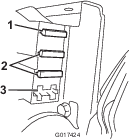
Adjusting the Handle Height
Note: The machine is shipped with the handle adjusted to the lowest position. The machine is normally operated with the handle telescoped out to its maximum height.
-
Loosen the 3 carriage bolts and nuts securing each side of the handle in the handle clamps (Figure 31).
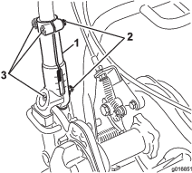
-
Pull up on the handle slowly and evenly on each side until it is in the desired operating position.
-
Tighten the carriage bolts and nuts to lock the adjustment.
Adjusting the Handle Angle
Adjusting the Throttle Control
-
Remove the console cover.
-
Loosen the 2 fasteners securing the throttle control (Figure 33).
-
Adjust the throttle control to the desired position.
-
Tighten the throttle-control fasteners.
-
Install the previously removed console cover.
Checking the Operation of the Interlock Switches
Caution
If the safety interlock switches are disconnected or damaged the machine could operate unexpectedly causing personal injury.
-
Do not tamper with the interlock switches.
-
Check the operation of the interlock switches daily and replace any damaged switches before operating the machine.
Checking the Operator-Presence Control (OPC) Interlock
-
Push the kickstand down with your foot and pull up on the handle support until the kickstand has rotated forward, over center.
-
Start the machine.
-
With the OPC released, attempt to engage the traction lever (Figure 34). The traction lever should not engage. If the traction lever engages, the interlock system needs service. Correct the problem before operating the machine; refer to Servicing the Traction Interlock Switch.
-
With the OPC pressed and the traction lever engaged, release the OPC (Figure 34). The traction lever should disengage. If the traction lever does not disengage, the interlock system needs service. Correct the problem before operating the machine. Refer to Servicing the Traction Interlock Switch.
-
With the OPC pressed and the shift lever moved to the left, engage the traction and reel drive, release the OPC (Figure 34). The traction lever should disengage. If the traction lever does not disengage, the interlock system needs service. Correct the problem before operating the machine; refer to Servicing the Traction Interlock Switch or Adjusting the Reel Control.
-
With the OPC pressed and the shift lever moved to the left, engage the traction and reel drive. Move the shift lever to the right to disengage the reel drive (Figure 23). The reel drive should disengage. If the reel drive does not disengage, the interlock system needs service. Correct the problem before operating the machine; refer to Servicing the Traction Interlock Switch.
-
Carefully lower the machine off the kickstand.
Checking the Traction-Interlock Switch
-
Ensure that the kickstand is down.
-
Press the OPC and engage the traction lever (Figure 23)
-
Use the key switch to start the machine. The InfoCenter LCD display lights up and display a message warning that the traction lever is engaged. If this warning does not appear, the interlock switch needs service. Correct the problem before operating the machine; refer to Servicing the Traction Interlock Switch.
-
Turn off the machine and return the traction lever to the NEUTRAL position.
Checking the Brake-Interlock Switch
-
Ensure that the kickstand is down.
-
With the machine on and the service brake engaged (not the parking–brake latch) with moderate force, press the OPC and engage the traction lever (Figure 23). The motor should labor to overcome the brake without producing errors on the InfoCenter LCD display. It may display a high power consumption advisory (smaller battery with a lightning bolt). If you get any other advisory, correct the problem before operating the machine.
-
With the machine on, engage the parking-brake latch, press the OPC, and engage the traction lever (Figure 23 and Figure 24). The motor should not run and you should get an advisory on the InfoCenter panel. If not, the interlock switch needs service. Correct the problem before operating the machine; refer to Servicing the Brake-Interlock Switch.
-
Turn off the machine and return the traction lever to the NEUTRAL position.
-
Carefully lower the machine off the kickstand.
Transporting the Machine to a Job Site
Transporting the Machine a Short Distance
Use the transport wheels to transport the machine a shorter distance.
-
Install the transport wheels; refer to Installing the Transport Wheels
-
Ensure that the traction and reel-drive lever is in the NEUTRAL position.
-
Ensure that the speed control is set to ZERO.
-
Start the machine; refer to Starting the Machine
-
Tip the front of the machine up, gradually move the traction control to the FORWARD position, and use the speed control to slowly increase the machine speed.
-
Adjust the speed control to operate the mower at the desired ground speed and transport the machine to the desired destination.
Transporting the Machine a Considerable Distance
Use a trailer to transport the machine a considerable distance. Use caution while loading and unloading the machine onto the trailer.
-
Carefully drive the machine onto the trailer.
-
Shut off the machine, engage the service brake, and use the parking-brake latch to hold the service brake in place.
-
Securely fasten the machine to the trailer.
Note: The Toro Trans Pro trailer can be used to transport the machine. For instructions on loading the trailer, refer to your trailer Operator’s Manual.
Important: Ensure that the machine is shut off while you transport it on a trailer, as damage can occur to the machine if it is on during transportation.
During Operation
During Operation Safety
General Safety
-
The owner/operator can prevent and is responsible for accidents that may cause personal injury or property damage.
-
Wear appropriate clothing, including eye protection; long pants; slip-resistant, substantial footwear; and hearing protection. Tie back long hair, secure loose clothing, and do not wear jewelry.
-
Do not operate the machine while ill, tired, or under the influence of alcohol or drugs. Keep bystanders, especially small children, out of the operating area. Shut off the machine if anyone enters the area.
-
Operate the machine only in good visibility and appropriate weather conditions. Do not operate the machine when there is the risk of lightning.
-
Before you start the machine, disengage all blade-attachment clutches, shift into neutral, and engage the parking brake.
-
Watch for holes, ruts, bumps, rocks, or other hidden objects. Uneven terrain could cause a slip-and-fall accident.
-
Use extreme care when approaching blind corners, shrubs, trees, or other objects that may block your view.
-
Always stand in the operating position (behind the handle) when starting and operating the machine.
-
Ensure that the grass basket is in place while mowing. Shut off the machine before emptying the basket.
-
Never leave a running machine unattended.
-
Do not tip the machine more than 25°.
-
Shut off the machine and disengage the drive to the cutting unit in the following situations:
-
Before fueling
-
Before clearing blockages
-
Before removing the grass basket
-
Before checking, cleaning, or maintaining the cutting unit
-
After striking a foreign object or if an abnormal vibration occurs. Inspect the cutting unit for damage and make repairs before starting and operating the machine
-
Before leaving the operating position
-
-
Disengage the drive to the cutting unit when transporting or not using the machine.
-
Watch out for traffic when crossing or near roadways.
-
Stop the blades whenever you are not mowing.
-
Use accessories and attachments approved by The Toro® Company only.
Slope Safety
-
Slopes are a major factor related to loss of control and rollover accidents, which can result in severe injury or death. The operator is responsible for safe slope operation. Operating the machine on any slope requires extra caution.
-
Evaluate the site conditions to determine if the slope is safe for machine operation including surveying the site. Always use common sense and good judgment when performing this survey.
-
Review the slope instructions, listed below, for operating the machine on slopes and review the conditions to determine whether you can operate the machine in the conditions on that day and at that site. Changes in the terrain can result in a change in slope operation for the machine.
-
Avoid starting, stopping, or turning the machine on slopes. Avoid making sudden changes in speed or direction. Make turns slowly and gradually.
-
Do not operate a machine under any conditions where traction, steering, or stability is in question.
-
Remove or mark obstructions such as ditches, holes, ruts, bumps, rocks, or other hidden hazards. Tall grass can hide obstructions. Uneven terrain could overturn the machine.
-
Be aware that operating the machine on wet grass, across slopes, or downhill may cause the machine to lose traction. Loss of traction may result in sliding and a loss of braking and steering.
-
Use extreme caution when operating the machine near dropoffs, ditches, embankments, water hazards, or other hazards. The machine could suddenly roll over if part of the traction goes over the edge or the edge caves in. Establish a safety area between the machine and any hazard.
-
Identify hazards at the base of the slope.
-
Starting the Machine
-
Ensure that the T-handle connector on the main wire harness is connected to the main power supply connector; refer to Figure 16.
-
Ensure that the traction and reel drive lever is in the NEUTRAL position; refer to Figure 35.
-
Insert the key into the key switch, turn the switch to the START position and hold it until the InfoCenter LCD display lights up, then release it to the RUN position.
Operating the Machine
-
Start the machine, set the speed control to the ZERO position, push down on the handle to raise the cutting unit, press the operator-presence control, move the traction lever to the FORWARD position (Figure 35), and gradually increase the speed control setting to transport the machine onto the collar of the green.
-
Return the speed control to the ZERO position.
-
Move the traction lever to the NEUTRAL position, then move the lever to the left and forward to the traction—FORWARD and reel drive—ENGAGED position (Figure 35).
-
Gradually increase the speed control setting until the machine is traveling at the desired ground speed, drive the machine out onto the green area, lower the front of the machine to the ground, and begin mowing.
Note: While mowing, you can move the speed control to the ZERO position. This stops the machine with the motor brake off, allowing you to pull the machine rearward to make course corrections. For more information on the automatic motor brake, refer to Automatic-Motor Brake.
Shutting Off the Machine
-
Move the traction and reel drive lever to the NEUTRAL position.
-
Turn the key switch to the OFF position and remove the key.
Operating Tips
Important: Grass clippings act as a lubricant when mowing. Operating the cutting unit excessively without grass clippings can damage the cutting unit.
Preparing to Mow
Ensure that the machine is carefully adjusted and is set evenly on both sides of the reel. For the best performance and battery life, set the bedknife to have a light contact with the reel. Improper mower adjustment is magnified in the appearance of the clipped turf.
If the transport wheels are installed on your machine, perform the following steps to remove the wheels:
-
Push the kickstand down with your foot and pull up on the handle support until the kickstand has rotated forward, over center.
-
Remove the transport wheels.
-
Carefully lower the machine off the kickstand.
Mowing the Green
The green should be mowed in a straight back-and-forth direction across the green. Avoid circular mowing or turning the mower on the green, as scuffing may occur.
Turning the mower should be done off the green by raising the cutting reel (pushing the handle down) and turning on the traction drum. If you enable the EZ-Turn switch, the traction unit slows down when you raise the cutting unit making the turn more manageable, especially for novice users.
Mowing should be done at a normal walking pace. Fast speeds save very little time and result in an inferior mowing job.
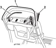
To assist in maintaining a straight line across the green and to keep the machine an equal distance from the edge of the previous cut, use the alignment stripes on the grass basket (Figure 36).
Operating the Machine in Low Light Conditions
When operating in low light conditions, use the LED Light Kit; contact your authorized Toro distributor.
Important: Do not use other light systems with this machine; they may damage the battery pack or electrical system.
Preparing to Transport the Machine after Mowing
-
Drive off the green, reduce the speed to the ZERO position, move the traction and reel drive lever to the NEUTRAL postion, and shut off the machine.
-
Empty the grass basket of clippings and install the grass basket on the mower.
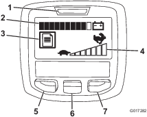
Using the InfoCenter LCD Display
The InfoCenter LCD display shows information about your machine such as the current battery charge, the speed, various diagnostics, and other information about the machine and the battery pack. Figure 37 illustrates the InfoCenter and the main information screen.
-
Power light/fault indicator—illuminates when you turn the machine on. You can return the key to the RUN position when this light illuminates. This light also blinks when there is a machine fault.
-
Battery charge indicator—when the battery has a full charge, all of the boxes in the indicator will be filled in with black. As power is used, boxes will be filled with white starting from the right and proceeding to the left as the battery drains. When only 1 box is still black, the battery pack is almost out of power and you should immediately proceed to charge the battery.
-
Fault log indicator—this icon indicates that there is a current fault log to review.
-
Speed control setting—the bars turn black from left to right the faster you set the speed control. When all bars are filled with white, the machine is at zero speed.
-
Menu access/back button—press this button to access the InfoCenter menus. You can also use it to back out of any menu you are currently using.
-
Down button—use this button to scroll down menus.
-
Right button—use this button to open a menu where a right arrow indicated additional content.
Note: The purpose of each button may change depending on what is required at the time. Each button has a label with an icon displaying its current function.
Using the Menus
To access the InfoCenter menu system, press the menu access button while at the main screen. This will bring you to the main menu. Refer to the following tables for a synopsis of the options available from the menus:
| Main Menu | |
| Menu Item | Description |
| Faults | The Faults menu contains a list of the recent machine faults. Refer to the Service Manual or your Authorized Toro Distributor for more information on the Faults menu and the information contained there. |
| Service | The Service menu contains information on the machine such as hours of use and battery usage and status. |
| Diagnostics | The Diagnostics menu lists various states that the machine currently has. You can use this to troubleshoot certain issues as it will quickly tell you which machine controls are on and which are off. |
| About | The About menu lists the model number, serial number, and software version of your machine. |
| Settings | The Settings menu allows you to customize the InfoCenter display. |
| Service Menu | |
| Menu Item | Description |
| Hours | Lists the total number of hours that the machine has been turned on. |
| Mow Time | Lists the total number of hours that the reel has been turned on. |
| Power Use | Lists the instantaneous power delivered by the battery in Watts. |
| Battery Charge | Lists the current battery charge as a percent of capacity. |
| Battery Current | Lists the instantaneous current delivered by the battery in Amps. |
| Battery Volts | Lists the battery potential in volts. |
| Energy | Lists the total energy delivered by the battery over its entire life in watt-hours. |
| Diagnostics Menu | |
| Menu Item | Description |
| Key On | Indicates whether the ignition key is on or off. |
| Key Start | Indicates whether the ignition key is in the Start position or not.. |
| PBrake Latch | Indicates whether the parking-brake latch is on or off. |
| EZ Turn | Indicates whether the EZ-Turn circuit is open or closed. |
| Traction | Indicates whether the traction lever is on or off. |
| Reel Enable | Indicates whether the reel is engaged or not. |
| Throttle | Indicates the throttle control setting in Volts (used to calculate the target rpm). |
| Target rpm | Lists the desired motor rpm as indicated by the speed control setting. |
| Motor rpm | Lists the actual motor rpm. |
| 12V Supply | Lists the sensor supply voltage #1 of the controller. |
| 5V Supply | Lists the sensor supply voltage #2 of the controller. |
| CAN Bus | Lists the machine communication bus status. |
| About Menu | |
| Menu Item | Description |
| Model | Lists the model number of the machine. |
| SN | Lists the serial number of the machine. |
| S/W Rev | Lists the revision number of the machine software. |
| Settings Menu | |
| Menu Item | Description |
| Language | Use this setting to change the language used on the InfoCenter. |
| Units | Use this setting to change the units used by the InfoCenter. The menu choices are English and Metric. |
| LCD Backlight | Use this setting to increase or decrease the brightness of the LCD display. |
| LCD Contrast | Use this setting to change the contrast between the dark and light areas of the LCD display. |
Note: If you inadvertently change the language or contrast to a setting where you can no longer understand or view the display, contact your Authorized Toro Distributor for assistance in resetting the display.
Releasing the Transmission
If the machine becomes disabled with the motor brake on, you can disengage the drum from the transmission to allow the machine to be maneuvered.
-
On the right rear corner of the machine, locate the traction engage/disengage lever next to the drive housing drum (Figure 38).
-
Rotate the lever rearward to disengage the transmission from the drum.
Important: Push the lever from the front to prevent your hand from being struck by the spring loaded lever.
-
Move the machine as needed
Important: If possible, do not tow the machine. If it is absolutely necessary, do not tow at any speed greater than 4.8 kph (3 mph); always disengage the transmission from the drum. Failing to do so will likely cause damage to the machine, especially the electrical components.
-
When finished, rotate the lever forward to engage the transmission to the drum.
Note: The service brake is still operational with the transmission disengaged from the drum.
After Operation
After Operation Safety
General Safety
-
Reduce the speed control before shutting off the machine.
-
Clean grass and debris from the machine to help prevent fires.
Transporting the Machine
After mowing, transport the machine away from the job site; refer to Transporting the Machine a Short Distance or Transporting the Machine a Considerable Distance.
Maintaining the Lithium Ion Battery Pack
Warning
The battery pack contains high voltage, which could burn or electrocute you.
-
Do not attempt to open the battery pack.
-
Do not place anything in the connector of the battery pack other than the wire harness connector that came with the product.
-
Use extreme care when handling a battery pack with a cracked case.
-
Use only the charger designed for the battery pack.
Charging the Battery Pack
Charge the battery pack when you are finished mowing for the day to ensure that it is fully charged for the next day’s mowing. Unlike other battery types, lithium ion batteries do not have a charge memory issue and do not need to be fully discharged before charging them.
Refer to the Lithium Ion Battery Charger Operator’s Manual for detailed instructions on charging the battery pack.
If you will be storing the mower for more than 10 days, ensure that you place it on the charger and leave the charger turned on. After 10 days of inactivity, the charger automatically switches to storage mode, during which it reduces and maintains the charge to 40% of the maximum charge. Refer to Before storage for more information on storing the machine and for removing the battery from storage mode.
Transporting the Battery Pack
The US Department of Transportation and international transportation authorities require that lithium ion batteries be transported using special packaging and only be transported by carriers certified to haul them. In the US, you are allowed to transport the battery when it is installed on the machine as battery powered equipment, with some regulatory requirements. Contact the US Department of Transportation or the appropriate government body in your country for detailed regulations on transportation of your eFlex or eFlex battery.
For detailed information on shipping the battery pack, refer to the Installation Instructions included with the Battery Shipping Kit (Model No. 120-4600). These instructions are available on www.Toro.com.
Caring for the Battery Pack
The lithium-ion-battery holds a sufficient charge to perform intended work during its life span. As time goes by, the total amount of work the battery is able to complete on a single charge gradually diminishes. The following table lists the approximate expected work that the machine should be capable of over the first 5 years of use:
| Year | Area Cut Per Full Charge |
| 1 | 4,240 m2 (45,600 ft2) |
| 2 | 4,070 m2 (43,800 ft2) |
| 3 | 3,900 m2 (42,000 ft2) |
| 4 | 3,790 m2 (40,800 ft2) |
| 5 | 3,600 m2 (39,000 ft2) |
Note: Your results may vary depending on the distance you need to transport the machine, the contact setting of the bedknife, and other factors as discussed in this section.
To achieve maximum life and use from your battery, apply the following care guidelines:
-
Do not open the battery pack. There are no user serviceable parts inside. If you open the pack you will void your warranty. The pack is protected by tamper-alerting devices.
-
Store/park the machine in a clean, dry garage or storage area, away from direct sunlight and heat sources. Do not store it in a location where the temperature drops below -25°C (-13°F) or rises above 45°C (113°F). Temperatures outside of this range will damage your battery. High temperatures during storage, especially at a high state of charge, reduces the life of the batteries.
-
When storing for more than 10 days, ensure that the machine is in a cool location, out of sunlight, and connected to the charger.
-
If you are mowing in hot conditions or in sunlight, the battery may overheat. If this happens, a high-temperature alert will appear on the InfoCenter LCD display. In this condition, the machine no longer operates with the reel engaged and the machine slows down.
Immediately drive the machine to a cool location out of the sun, turn off the machine, and allow the battery to cool fully before resuming operation.
-
Keep the battery pack cover clean. The white color reflects sunlight and slows the heat buildup in the battery pack. A dirty cover increases the heat in the battery pack each day and reduces the energy capacity.
-
Adjust the bed knife to reel contact to be as light as possible. This reduces the power needed to run the reel and increases the amount of work the machine performs on each charge.
Maintenance
Note: Download a free copy of the electrical or hydraulic schematic by visiting www.Toro.com and searching for your machine from the Manuals link on the home page.
Note: Determine the left and right sides of the machine from the normal operating position.
Recommended Maintenance Schedule(s)
| Maintenance Service Interval | Maintenance Procedure |
|---|---|
| Before each use or daily |
|
| After each use |
|
| Every 1,000 hours |
|
| Before storage |
|
| Yearly |
|
Important: Refer to your battery Owner’s Manual for additional maintenance procedures.
Pre-Maintenance Procedures
Pre-Maintenance Safety
-
Disengage the drives and the cutting unit, engage the parking brake, and shut off the machine. Wait for all movement to stop before adjusting, cleaning, or repairing the machine.
-
If the machine must be running to perform a maintenance adjustment, keep your hands, feet, clothing, and any parts of the body away from the cutting unit, attachments, and any moving parts. Keep bystanders away.
-
Keep all parts in good working condition and all hydraulic fittings tight. Replace all worn, damaged, or missing parts and decals. Keep all fasteners tight to ensure that the machine is in safe working condition.
-
Check the grass catcher components frequently and replace them when necessary.
-
Clean grass and debris from the cutting unit, drives, mufflers, and cooling screens to help prevent fires.
-
Carefully release pressure from components with stored energy.
-
If major repairs are ever needed or if assistance is desired, contact an authorized Toro distributor.
-
To ensure optimum performance and continued safety certification of the machine, use only genuine Toro replacement parts and accessories. Replacement parts and accessories made by other manufacturers could be dangerous, and such use could void the product warranty.
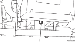
Disconnecting the Battery
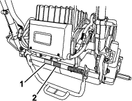
Before performing maintenance on the machine, disconnect the machine from the battery pack by pulling the T-handle connector off the main power supply connector (Figure 39).
Lubrication
Greasing the Motor Coupler
| Maintenance Service Interval | Maintenance Procedure |
|---|---|
| Yearly |
|
Grease Type: General-purpose grease.
-
Shut off the machine and disconnect the battery pack.
-
Remove the 2 bolts that secure the motor to the transmission case (Figure 40).
-
Pull the motor out and away from the transmission case.
-
Add 1 to 2 pumps of grease from a grease gun to the female coupler in the transmission case (Figure 40).
-
Install the motor and secure it with the 2 bolts that you removed previously. Torque the bolts to 29 to 33 N∙m (21 to 25 ft-lb).
Electrical System Maintenance
Electrical System Safety
Disconnect the battery before making any repairs. Disconnect the negative terminal first and the positive last. Connect the positive first and negative last.
Servicing the Battery Pack
The only user serviceable parts in the battery pack are the labels and the fuse. If you attempt to open the main compartment of the battery pack you will void your warranty. If you are having problems with your battery pack, contact your authorized Toro distributor for help.
Warning
The battery pack contains high voltage which could burn or electrocute you.
-
Do not attempt to open the battery pack.
-
Do not place anything in the connector of the battery pack other than the wire harness connector that came with the product.
-
Use extreme care when handling a battery pack with a cracked case.
-
Only use the charger designed for the battery pack
Shipping the Battery Pack for Service
If your battery pack requires service, contact your Authorized Toro Distributor for assistance. If you must ship the battery pack, obtain the Battery Shipping Kit (Part No. 120-4600). This kit contains the proper tape, labeling, and instructions you will need to ship the battery pack.
Important: Failure to correctly pack and label the battery pack for shipping can result in large fines. Refer to the instructions included in the Battery Shipping Kit (Part No. 120-4600), available for free on www.Toro.com.
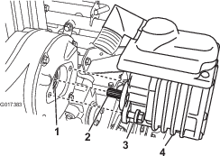
Replacing Fuses
If the machine does not turn on, even after charging, check the machine fuses as follows:
-
Turn off the machine and disconnect the battery pack.
-
Remove the 2 rear screws from the electrical box, loosen the 2 upper screws, and remove the box cover (Figure 41).
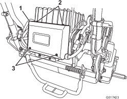
-
Check the fuses in the fuse block (Figure 42).
-
If any fuse is blown, replace them with a fuse of the appropriate voltage and amperage (Figure 42).
Important: All fuses on the machine are rated for 80 V. Do not use 12 V automotive fuses.
-
If the fuses are not blown, check the battery pack fuse as follows:
-
Raise the battery platform; refer to Installing the Battery Pack.
-
Remove the fuse cover (Figure 43).
-
Check the fuse and replace it if it is blown. Use only a Toro fuse (Part No. 119-1208) to replace this fuse. This fuse is specially designed for the battery pack. Other fuses may cause irreversible damage to the pack.
-
Replace and secure the fuse cover. Torque the cover screw to 0.34 N∙m (3 in-lb).
-
Lower and secure the battery platform.
-
-
Servicing the Traction Interlock Switch
Use the following procedure if the traction-interlock switch needs adjustment or replacement.
-
Turn off the machine and disconnect the battery pack.
-
Remove the control panel.
-
Engage the traction lever.
-
Loosen the interlock switch mounting fasteners (Figure 44).
-
Place a 1.6 mm (0.062 inch) thick shim between the traction lever and the interlock switch (Figure 44).
-
Tighten the interlock switch mounting fasteners. Recheck the gap. The traction lever must not contact the switch.
-
Engage the traction lever and check the gap. The normal operating range is between 0.76 to 3.05 mm (0.03 to 0.12 inch). With the traction lever engaged, verify that the switch loses continuity. Replace the switch if necessary.
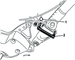
Servicing the Mow Sensor
-
Shut off the machine and disconnect the battery pack.
-
Remove the control panel.
-
Push the traction lever to the left and engage the mower.
-
Loosen the mow sensor mounting fasteners (Figure 44).
-
Place a 1.6 mm (0.062 inch) thick shim between the mow sensor flag and the mow sensor (Figure 44).
-
Tighten the sensor mounting fasteners. Check the gap. The flag must not contact the sensor.
-
Engage the traction lever in mowing mode and verify that the switch loses continuity. Replace the sensor if necessary.
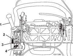
Servicing the Brake-Interlock Switch
-
Shut off the machine and disconnect the battery pack.
-
Remove the console cover.
-
Engage the service-brake lever and engage the parking-brake latch.
-
Loosen and remove the interlock switch mounting fasteners (Figure 45).
-
Place a 1.6 mm (0.062 inch) thick shim between the parking-brake latch and the interlock switch (Figure 45).
-
Install and tighten the interlock switch mounting fasteners. Check the gap. The latch must not contact the switch.
-
Engage the brake lever and rotate the latch. Verify that the switch loses continuity. Replace the switch if necessary.
Brake Maintenance
Adjusting the Service/Parking Brake
If the service/parking brake slips when operated, adjust the cable as follows:
-
Turn off the machine and disconnect the battery pack.
-
Move the service/parking brake lever to the OFF position.
-
Remove the console cover.
-
To increase the cable tension, loosen the upper cable jam nut and tighten the lower cable jam nut (Figure 45) until a force of 156 N (35 lb) applied to the brake lever handle is required to release the parking-brake latch.
Important: Do not over adjust or the brake band may drag.
Belt Maintenance
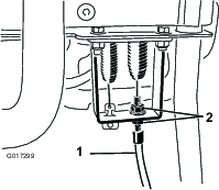
Inspecting the Reel Drive Belt
| Maintenance Service Interval | Maintenance Procedure |
|---|---|
| Every 1,000 hours |
|
Make sure that the reel drive belt is properly tensioned to ensure proper operation of the machine and unnecessary wear.
-
Turn off the machine and disconnect the battery pack.
-
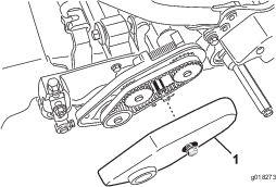
Loosen the flange bolt that secures the belt cover and remove the belt cover to expose the belt (Figure 47).
-
Adjust the belt tension by doing the following steps:
-
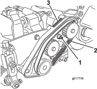
Loosen the bearing housing mounting nut (Figure 48).
-
Using a 16 mm (5/8 inch) wrench, rotate the bearing housing to ensure that it operates freely.
-
Clean any debris from inside the belt compartment and from around the compression spring (Figure 48).
-
Ensure that the compression spring is applying the proper tension on the belt.
-
Tighten the bearing housing mounting nut.
-
Install the belt cover.
-
Accessing the Transmission Cover Hole
Remove the rubber plug (Figure 49) from the hole in the front of the transmission if you need to access the reel clutch.
Important: Do not operate the machine without the rubber plug.
Engaging/Disengaging the Transmission-Belt Tensioner
The transmission belt is tensioned by a spring-loaded idler pulley. If you must engage or disengage the belt tension, use a 3/8-inch wrench to rotate the engage/disengage shaft (Figure 49) to the desired position. Rotating the shaft 1/4-turn (90°) clockwise disengages the idler from the belt (Figure 50).
Note: You must disengage the belt tension before removing the transmission cover
Note: The transmission belt is properly tensioned when the alignment marks on the transmission cover and the engagement shaft are aligned.
Controls System Maintenance
Adjusting the Reel Control
If the reel control does not properly engage, an adjustment is required.
-
Turn off the machine and disconnect the battery pack.
-
Ensure that the reel control is disengaged.
-
At the transmission bulkhead, adjust the reel-control cable (Figure 51), to attain a spring length of 70.6 to 72.4 mm (2.78 to 2.85 inches).
-
At the control handle bulkhead, loosen the reel-control cable until there is slack in the cable (Figure 52).
-
At the control handle bulkhead, tighten the reel-control cable enough to remove the slack from the cable without extending the spring.
-
Check the operation as follows:
-
Verify that the reel clutch teeth disengage when the clutch is released and the reel clutch teeth do not bottom out when engaged.
Note: Remove the rubber plug (Figure 49) from the hole in the front of the transmission to view reel clutch.
-
The reel stopping time must be less than 7 seconds with the reel to bedknife backed off.
-
Refer to the Service Manual or contact your authorized Toro distributor for further assistance.
-
Cleaning
Cleaning the Machine
| Maintenance Service Interval | Maintenance Procedure |
|---|---|
| After each use |
|
After each use, wash the machine with mild detergent and water. Do not pressure wash the machine. Avoid excessive use of water, especially near the shift-lever plate, the InfoCenter, the power center, and the machine power connector. Clean the motor to provide proper cooling during operation. Also, keep the battery pack as clean as possible so that it maintains a white color. This reflects sunlight and keeps the battery from overheating in the sun.
Important: Always store or park the machine out of direct sunlight, as heating from the sun reduces the battery-pack life span.
Storage
Storage Safety
-
Never store the machine where there is an open flame, spark, or pilot light, such as on a water heater or on other appliances.
-
Allow the machine to cool before you store the machine in any enclosure.
Storing the Machine
-
Clean the machine; refer to Cleaning the Machine.
Important: You can wash the machine with mild detergent and water. Do not pressure-wash the machine. Avoid excessive use of water, especially near the shift-lever plate, the InfoCenter, the power center, and the machine power connector.
-
Store the machine in a cool, clean, dry garage or storage area, away from direct sunlight. Do not store it in a location where the temperature drops below -25°C (-13°F) or rises above 45°C (113°F). Temperatures outside of this range will damage your battery.
Important: The temperature that the battery pack is stored at will affect its long-term life. Storage for long periods of time at high temperatures will reduce the life of the battery pack, especially if the pack is stored with a high charge. Where possible store the machine in a cool (not below freezing) location.
-
Connect the battery to the charger and keep the charger plugged into a power outlet and turned on for the duration of storage.
Important: After 10 days, the charger enters a storage maintenance mode, adjusting the battery to a charge of 40% of maximum. This charge level during long-term storage ensures the full life of the battery. If you do not keep the battery pack on the charger and allow it to enter storage mode, the high state of charge in the pack will shorten the life of the battery, especially if stored in warm conditions.
-
Check and tighten all the bolts, nuts, and screws. Repair or replace any part that is worn or damaged.
-
Paint all scratched or bare metal surfaces. Paint is available from your Authorized Service Dealer.
-
Cover the machine to protect it and keep it clean.
Removing the Machine from Storage
-
Turn off and disconnect the charger from the machine.
-
Connect the T-handle connector to the main power connector.
-
Turn on the machine and wait for 20 seconds.
-
Turn off the machine and disconnect the battery.
-
Connect the battery to the charger and turn on the charger.
Note: The charger will enter the normal charge mode and charge the battery to full capacity.