Introduction
Important: The term PTO switch is the equivalent to cutting unit engagement switch.
Warning
CALIFORNIA
Proposition 65 Warning
This product contains a chemical or chemicals known to the State of California to cause cancer, birth defects, or reproductive harm.
Setup
Preparing to Install the PTO Switch Kit
Warning
Battery terminals or metal tools could short against metal component, causing sparks. Sparks can cause the battery gasses to explode, resulting in personal injury.
-
When removing or installing the battery, do not allow the battery terminals to touch any metal parts of the machine.
-
Do not allow metal tools to short between the battery terminals and metal parts of the machine.
Warning
Incorrect battery cable routing could damage the machine and cables, causing sparks. Sparks can cause the battery gasses to explode, resulting in personal injury.
-
Always disconnect the negative (black) battery cable before disconnecting the positive (red) cable.
-
Always connect the positive (red) battery cable before connecting the negative (black) cable.
-
Locate the wiring schematic for your machine; refer to the Operator’s Manual, Parts Catalog, Service Manual, or Electrical Schematic Manual for your product.
-
Move the machine to a level surface.
-
Lower the cutting units, engage the parking brake, shut off the engine, and remove the key.
-
Disconnect the negative-battery cable from the battery; refer to the Operator’s Manual for your machine.
-
Access the PTO switch in the control panel of the machine.
Removing the 5-Socket Connector
-
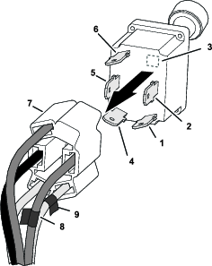
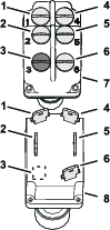
In the circuit identification table that follows, record the insulation colors for the wires assembled to the 5-socket connector (Figure 1) for the related PTO switch contact letters:
Note: Your machine may have either 4 wires or 5 wires at the 5-socket connector for the PTO switch.
Circuit Identification Table Switch contact circuits Record the wire insulation color in the space below: (example) (example) A B (mark the 5-socket connector wire) C (mark the 5-socket connector wire) D E -
Use electrical tape to mark the wires of the 5-socket connector aligned with the PTO switch circuit B and C contacts (Figure 1).
-
Remove the 5-socket connector from the PTO switch.
Removing the PTO Switch
-
Remove the jam nut and lock internal-tooth washer that secures the PTO switch to the control panel.
-
Remove the PTO switch from the control panel.
Installing the Adapter Wire Harness
Parts needed for this procedure:
| Adapter wire harness | 1 |
| PTO Switch | 1 |
Preparing the Adapter Wire Harness
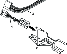
Note: The Adapter wire harness has wires with insulation colors for a variety of machines. You need no more than 5 wires of the adapter wire harness.
-
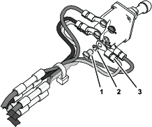
Identify the wire colors of the adapter wire harness that are not in the machine wire harness at the 5-socket connector for the PTO switch (Figure 2).
-
Remove the wires with insulation colors that you found in step 1.
Installing the Harness Adapter
-
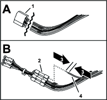
At the 5-socket connector for the PTO, cut the wires close to the connector (Figure 3).
-
Strip 9 mm (3/8 inch) of the insulations from the ends of the wires that you cut in step 1.
-
Match the insulation color of the wires you striped in step 2 to the insulation color of wires in the wire-harness adapter (Figure 3).
-
Insert the wire into the butt-splice connector and crimp the connector (Figure 3).
-
Use a heat gun to shrink the insulator of the butt-splice connector
-
Repeat steps 3 through 5 for the remaining wires of the PTO switch circuits (Figure 3).
Assembling the Wire-Harness Adapter to the PTO Switch
-
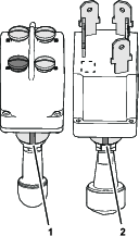
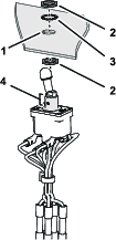
Identify the keyway slots in the new and old PTO switches (Figure 4).
-
With the keyway slots aligned, identify the contact locations of the new and old PTO switches (Figure 5).
-
Remove the screw and lock washer for circuit B from the new PTO switch (Figure 5).
-
Using the circuit identification table in Removing the PTO Switch, assemble the ring terminals of the wire-harness adapter for switch contact circuits B (marked with tape) onto the new PTO switch with the machine screw and lock washer (Figure 6).
-
Remove the screw and lock washer for circuit C from the new PTO switch (Figure 5).
-
Using the circuit identification table in Removing the 5-Socket Connector, assemble the ring terminals of the wire-harness adapter for switch contact circuits C (marked with tape) onto the new PTO switch with the machine screw and lock washer (Figure 6).
-
Using the circuit identification table, assemble the ring terminals for contact circuits A, D, and if applicable E to the new PTO switch with the machine screws and lock washers (Figure 5 and Figure 6).
Installing the PTO Switch
Connecting the Battery
Connect the negative-battery cable to the battery; refer to the Operator’s Manual for your machine.
Testing the PTO Switch and Finishing the Installation
-
Set the PTO switch to the ON position.
-
Start the engine.
The engine should not start when the PTO switch is in the ON position.
Important: If the engine starts, engage the parking brake, shut off the engine, remove the key, and check the wire connections at the PTO switch.
-
Set the PTO switch to the OFF position.
-
Start the engine.
-
Cycle the PTO switch to the ON and OFF position several times to check the function of the switch.
-
Set the PTO switch to the ON position and lift out of the seat.
The engine should shut off.
Important: If the engine continues to run, engage the parking brake, shut off the engine, remove the key, and check the wire connections.
-
Set the PTO switch to the OFF position, engage the parking brake, move the key switch to the OFF position, and remove the key.
-
Assemble the control panel that you remove in step 5 of Preparing to Install the PTO Switch Kit to the machine.