


Maintenance
Note: Determine the left and right sides of the machine from the normal operating position.
Important: Refer to your engine Operator's Manual for additional maintenance procedures.
Recommended Maintenance Schedule(s)
| Maintenance Service Interval | Maintenance Procedure |
|---|---|
| After the first 50 operating hours |
|
| Before each use or daily |
|
| Every 25 hours |
|
| Every 100 hours |
|
| Every 200 hours |
|
| Every 600 hours |
|
| Before storage |
|
Lubrication
Lubrication
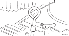
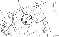
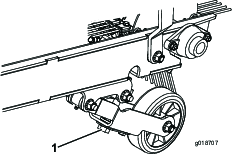
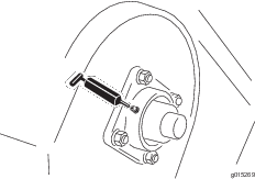
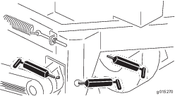
The Rake-O-Vac has grease fittings that must be lubricated regularly with No. 2 General Purpose Lithium Base Grease. Lubricate the bearings after every 30 hours of operation or whenever machine is washed with water. Bearings and bushings must be lubricated daily when operating conditions are extremely dusty and dirty. Dusty and dirty operating conditions could cause dirt to get into the bearings and bushings, resulting in accelerated wear. The grease fittings that must be lubricated are: the gauge wheel bearings, the reel shaft bearings, the impeller shaft bearings, the jackshaft bearings, and the left and right trailing arms.
-
Wipe the grease fittings clean to ensure that foreign matter cannot be forced into the bearing or bushing.
-
Pump grease into the bearing or bushing (Figure 11, Figure 12, and Figure 13).
-
Wipe up any excess grease.
Engine Maintenance
Servicing the Air Cleaner
Check the air cleaner housing for damage which could cause an air leak. Replace if damaged. Check the whole intake system for leaks, damage or loose hose clamps
Removing the Air Filters
-
Stop the engine, remove the key, and wait for all moving parts to stop before leaving the operating position.
-
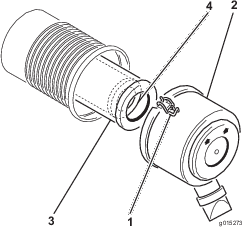
Release latches securing air cleaner cover to air cleaner body. Separate cover from body (Figure 14).
-
Clean the inside of the air cleaner cover with compressed air.
-
Gently slide the primary filter out of the air cleaner housing (Figure 14).
Note: Avoid knocking the filter into the side of the housing.
-
Remove the safety filter only if you intend to replace it.
Important: Never attempt to clean the safety filter. If the safety filter is dirty, then the primary filter is damaged. Replace both filters.
-
Inspect the primary filter for damage by looking into the filter while shining a bright light on the outside of the filter. Holes in the filter will appear as bright spots. If the filter is damaged, discard it.
Servicing the Primary Air Filter
-
If the primary air filter is dirty, bent, or damaged, replace it.
-
Do not clean the primary air filter.
Servicing the Safety Air Filter
Important: Never attempt to clean the safety air filter. If the safety air filter is dirty, then the primary air filter is damaged. Replace both filters.
Installing the Filters
Important: To prevent engine damage, always operate the engine with both air filters and cover installed.
-
If installing new filters, check each filter for shipping damage. Do not use a damaged filter.
-
If the safety filter is being replaced, carefully slide it into the filter body (Figure 14).
-
Carefully slide the primary filter over the safety filter (Figure 14).
Note: Ensure that the primary filter is fully seated by pushing on its outer rim while installing it.
Important: Do not press on the soft inside area of the filter.
-
Clean the dirt ejection port located in the removable cover. Remove the rubber outlet valve from the cover, clean the cavity and replace the outlet valve.
-
Install the air cleaner cover with the side indicated as up facing upward and secure the latches (Figure 14).
Changing the Engine Oil and Filter
Note: Change the oil and filter more frequently when operating conditions are extremely dusty or sandy.
Oil Type: Detergent oil (API service SJ, SK, SL, or higher)
Crankcase Capacity: w/filter, 1.9 liters (2.0 quarts)
-
Start the engine and let it run for five minutes. This warms the oil so it drains better.
-
Park the machine so that the drain side is slightly lower than the opposite side to ensure that the oil drains completely.
-
Set the parking brake, stop the engine, and remove the key.
-
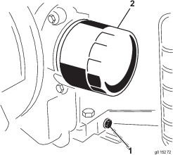
Place a pan below the oil drain. Remove the oil drain plug to allow the oil to drain (Figure 15).
-
When the oil has drained completely, replace the plug.
Note: Dispose of the used oil at a certified recycling center.
-
Place a shallow pan or rag under the filter to catch oil.
-
Remove the old filter and wipe the surface of the filter adapter gasket.
-
Pour the new oil of the proper type through the center hole of the filter. Stop pouring when the oil reaches the bottom of the threads.
-
Allow a minute or two for the oil to be absorbed by filter material, then pour off the excess oil.
-
Apply a thin coat of new oil to the rubber gasket on the replacement filter.
-
Install the replacement oil filter to the filter adapter. Turn the oil filter clockwise until the rubber gasket contacts the filter adapter, then tighten the filter an additional 1/2 turn. Do not over tighten.
-
Check the oil level.
-
Slowly add additional oil to bring the level to the full mark on the dipstick.
-
Replace the fill cap.
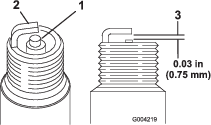
Servicing the Spark Plugs
Ensure that the air gap between the center and side electrodes is correct before installing each spark plug. Use a spark plug wrench for removing and installing the spark plugs and a gapping tool/feeler gauge to check and adjust the air gap. Install new spark plugs if necessary.
Type: Champion RC12YC or equivalent. Air Gap: 0.75 mm (0.03 inch)
Removing the Spark Plugs
-
Stop the engine, set the parking brake, and remove the key.
-
Pull the wires off of the spark plugs.
-
Clean around the spark plugs.
-
Remove both spark plugs and metal washers.
Checking the Spark Plugs
-
Look at the center of both spark plugs (Figure 16). If you see light brown or gray on the insulator, the engine is operating properly. A black coating on the insulator usually means the air cleaner is dirty.
Important: Never clean the spark plugs. Always replace the spark plugs when they have a black coating, worn electrodes, an oily film, or cracks.
-
Check the gap between the center and side electrodes (Figure 16).
-
Bend the side electrode (Figure 16) if the gap is not correct.
Installing the Spark Plugs
-
Thread the spark plugs into the spark plug holes.
-
Tighten the spark plugs to 27 N-m (20 ft-lb).
-
Push the wires onto the spark plugs.
Remove Debris from the Engine
To ensure proper cooling, keep the grass screen, cooling fins, and other external surfaces of the engine clean at all times.
Every 100 hours of operation (more often under extremely dusty, dirty conditions) remove the blower housing and other cooling shrouds. Clean the cooling fins and external surfaces as necessary. Make sure the cooling shrouds are reinstalled.
Note: Operating the engine with a blocked grass screen, dirty or plugged cooling fins, or cooling shrouds removed, will cause engine damage due to overheating.
Close sectionFuel System Maintenance
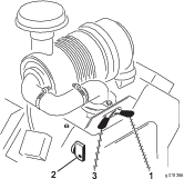
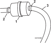
Replacing the Fuel Filter
Important: Never re-install a dirty filter if it is removed from the fuel line.
-
Stop the engine, remove the key, and wait for all moving parts to stop before leaving the operating position.
-
Allow the machine to cool down.
-
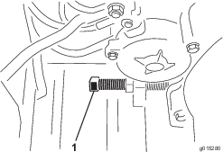
Place a clean container under the fuel filter (Figure 17).
-
Loosen the clamps securing the fuel filter to the fuel lines.
-
Remove the filter from the fuel lines.
-
Install a new filter to the fuel lines with the clamps previously removed. Filter is to be mounted so that the arrow points toward the carburetor.
-
Wipe up any spilled fuel.
Electrical System Maintenance
Servicing the Battery
Warning
Battery posts, terminals, and related accessories contain lead and lead compounds, chemicals known to the State of California to cause cancer and reproductive harm. Wash hands after handling.
Danger
Battery electrolyte contains sulfuric acid which is a deadly poison and causes severe burns.
-
Do not drink electrolyte and avoid contact with skin, eyes, or clothing. Wear safety glasses to shield your eyes and rubber gloves to protect your hands.
-
Fill the battery where clean water is always available for flushing the skin.
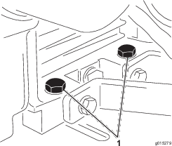
The battery electrolyte level must be properly maintained and the top of the battery kept clean. If the machine is stored in a location where temperatures are extremely high, the battery will run down more rapidly than if the machine is stored in a location where temperatures are cool.
Check the electrolyte level every 25 operating hours or, if machine is in storage, every 30 days.
Maintain the cell level with distilled or demineralized water. Do not fill the cells above the bottom of the split ring inside each cell.
Keep the top of the battery clean by washing it periodically with a brush dipped in ammonia or bicarbonate of soda solution. Flush the top surface with water after cleaning. Do not remove the fill caps while cleaning.
The battery cables must be tight on the terminals to provide good electrical contact.
Warning
Incorrect battery cable routing could damage the machine and cables causing sparks. Sparks can cause the battery gasses to explode, resulting in personal injury.
-
Always disconnect the negative (black) battery cable before disconnecting the positive (red) cable.
-
Always connect the positive (red) battery cable before connecting the negative (black) cable.
If corrosion occurs at the terminals, disconnect the cables (negative (–) cable first) and scrape clamps and terminals separately. Reconnect the cables (positive (+) cable first) and coat the terminals with petroleum jelly.
Warning
Battery terminals or metal tools could short against metal tractor components causing sparks. Sparks can cause the battery gasses to explode, resulting in personal injury.
-
When removing or installing the battery, do not allow the battery terminals to touch any metal parts of the machine.
-
Do not allow metal tools to short between the battery terminals and metal parts of the machine.
Drive System Maintenance
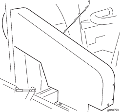
Tire Maintenance
Checking the Tire Pressure
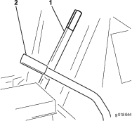
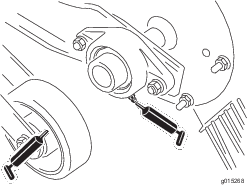
Maintain the air pressure in the front and rear tires at 193 kPa (28 psi). Check the pressure at the valve stem (Figure 18) before each use.

Changing the Tires
-
Park the machine on a flat, level surface. Block the other tire to prevent accidental rolling or injury.
-
Place the jack under the frame or axle shaft behind the wheel and jack up the wheel until it just contacts the floor.
Warning
A 2000 lb. capacity hydraulic jack should be used when changing a tire.
-
Loosen all lug bolts and continue to jack up until the tire can be removed.
-
Reverse the above procedure to install a tire. Torque the lug bolts to 95–122 N-m (70–90 ft-lb).
Belt Maintenance
Inspecting the Belts
Note: It is not necessary to remove the upper belt guard (Figure 19) to check the belt tension. If for some reason the belt guard must be removed, remove the 4 bolts, washers, and nuts securing the guard to the frame. Never operate the machine without the guards in place.
Inspecting the Impeller Drive Belt
Check the tension by depressing the belt at the mid span of the impeller and clutch pulleys with 18–22 N (4–5 lbs) of force. The belt should deflect 1.27 cm (.5 inches). If the deflection is incorrect, proceed to Adjusting the Impeller Drive Belt. If the deflection is correct, continue normal operation (Figure 19).
Close sectionInspecting the Jackshaft Belt
Check the tension by depressing the belt at mid span of the jackshaft and clutch pulleys with 18–22 N (4–5 lbs) of force. The belt should deflect 6.35 mm (.25 inches). If the deflection is incorrect, proceed to Adjusting the Jackshaft Belt. If the deflection is correct, continue normal operation (Figure 19).
Close sectionInspecting the Reel Drive Belt
Check the tension by depressing the belt at mid span of the idler pulley and the reel driver pulley with 111–129 N (25–29 lbs) of force. The belt should deflect 6.35 mm (.25 inches). If the deflection is incorrect, proceed to Adjusting the Reel Drive Belt. If the deflection is correct, continue normal operation.
Close sectionAdjusting the Belts
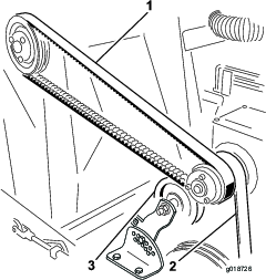
Adjusting the Impeller Drive Belt
-
Loosen the engine mounting bolts (Figure 21).
-
Turn the belt adjusting bolt until the desired belt tension is obtained. Slightly tighten the engine mounting bolts. Adjust the engine so that it is parallel with frame. Continue tightening the engine mounting bolts (Figure 22).
-
Whenever the impeller belt is adjusted it is necessary to readjust the jackshaft belt (engine drive) or chain (PTO drive).
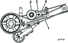
Adjusting the Jackshaft Belt
-
Remove the 4 bolts, washers and nuts securing the upper shroud to the frame (Figure 19).
-
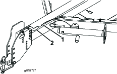
Remove the nut and bolt securing the idler pulley bracket to the tension adjusting bracket (Figure 23).
-
Press down on the idler pulley until the desired tension is obtained and the holes in the idler pulley bracket and the tension adjusting bracket are aligned.
-
Install the bolt and nut to secure the adjustment.
-
Reinstall the upper shroud.
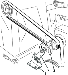
Adjusting the Reel Drive Belt
-
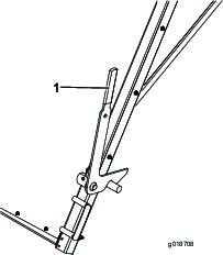
Remove the nut and bolt securing the idler pulley bracket (bolt in slotted hole in bracket) to the tension adjusting bracket (Figure 24).
-
Press down on the idler pulley until the desired tension is obtained and the holes in the idler pulley bracket and the tension adjusting bracket are aligned.
-
Install the bolt and nut to secure the adjustment.
Replace the rubber flap when it becomes worn or damaged.
Caution
Change rubber flap on a flat, level surface and block wheels to prevent sweeper from rolling. Failure to do so may result in personal injury.
-
Remove the 10 bolts, washers, and nuts on the mounting flap and flap retainer (Figure 25).
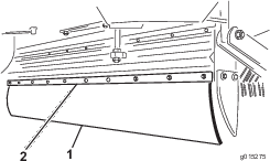
-
Replace with the new rubber flap and fasten it securely.
-
Remove the bolts and lockwashers one at a time and screw them into the adjoining holes (Figure 26).
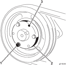
-
Turn each bolt the same number of times until the lock separates. The pulley will now slide off of the shaft.
-
Place the machine on a hard and level surface.
-
Raise the front of the sweeper as high as possible by lowering the jack.
-
Raise the reel to the highest position.
-
Remove the lower belt guard and reel drive belt (Figure 24).
-
Remove the 2 bolts, lockwashers, and nuts securing the reel shaft bearings to the reel support arms on each side of the sweeper. Lower the flex tip reel to the ground.
-
Lift the reel support arms to the highest position.
-
Slide the end of the rake rearward and pull it out from under the machine.
-
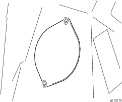
Remove the bolt and locknut from one end of the reel (Figure 27).
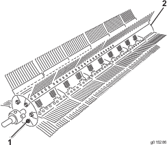
-
Remove the locknut only from the opposite end of the reel.
-
Drive the rod from the end plate. Drive the rod from the end without the tab welded to it.
-
Remove the finger plates or rods as required and replace.
-
Line up the finger plate with the rod and drive the rod back through the end plate.
-
Attach the bolt, locknuts, and hook up the springs.
-
Remove the tine retainer and slide the damaged tine out (Figure 28).
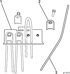
-
Bend the new tine in half and slide it into position.
-
Place the tine bracket over the curved end of the tine and fasten it securely with the bolt and lockwasher.
-
Remove the brush from the sweeper.
-
Loosen the clamps with an Allen wrench and remove it from the brush halves (Figure 29).
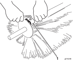
-
Separate the brush halves and discard the damaged section(s) (Figure 30).
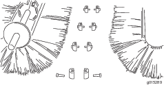
-
Install the new brush section by pushing them together and securing both ends with the brush clamps. When the ends have been secured, fasten the brush with the remaining clamps.
Cleaning the Blower Housing
Warning
Before removing any debris from blower housing, disengage P.T.O. drive, stop engine(s) and make certain all moving parts have stopped or personal injury may occur.
-
Make sure the impeller has stopped rotating before removing the access plates.
-
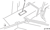
Loosen the 2 wing nuts securing the access plate (Figure 31).
-
Swing the access plate to one side allowing the removal of debris.
-
After the debris has been removed, lower the access plate and secure with the wing nuts. Repeat the procedure on the other access plate.