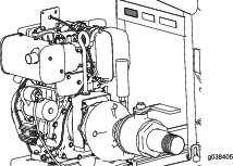


Maintenance
Important: Before performing any maintenance procedures, first shut off the engine and wait 5 minutes to allow all moving parts to come to a complete stop and cool.
Recommended Maintenance Schedule(s)
| Maintenance Service Interval | Maintenance Procedure |
|---|---|
| After the first 25 hours |
|
| After the first 50 hours |
|
| Before each use or daily |
|
| After each use |
|
| Every 50 hours |
|
| Every 100 hours |
|
| Every 200 hours |
|
| Every 400 hours |
|
Important: Refer to your engine owner's manual for additional maintenance procedures.
Pre-Maintenance Procedures
Pre-Maintenance Safety
-
Before adjusting, cleaning, repairing, or leaving the machine, do the following:
-
Move the machine on a level surface.
-
Shut off the engine and remove the key.
-
Wait for all moving parts to stop.
-
Allow machine components to cool before performing maintenance.
-
-
If possible, do not perform maintenance while the engine is running. Keep away from moving parts.
-
Use adequate support to support the machine or components when required.
-
Carefully release pressure from components with stored energy.
Preparing the Machine for Maintenance
-
Park the transport vehicle on a level surface and chock the tires, or remove the machine from the transport vehicle.
-
Ensure that the engine and muffler are cool.
-
Turn the electric-start switch to the OFF position.
Lubrication
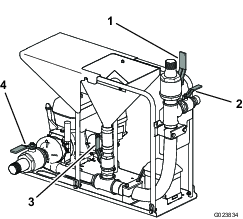
Lubricating the Pump
| Maintenance Service Interval | Maintenance Procedure |
|---|---|
| Every 100 hours |
|
Grease Type: NLGI #1 heavy-duty EP grease
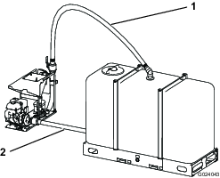
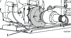
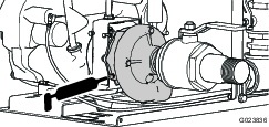
Use a grease gun to pump grease into the grease fitting on the side of the pump (Figure 19).
Engine Maintenance
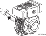
Servicing the Air Cleaner
| Maintenance Service Interval | Maintenance Procedure |
|---|---|
| Before each use or daily |
|
| Every 50 hours |
|
| Every 200 hours |
|
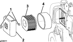
Important: Do not operate the engine without the air filter assembly; extreme engine damage will occur.
-
Set the throttle to slow, shut off the engine, and wait for all moving parts to stop.
-
Turn the fuel shutoff lever to the OFF position.
-
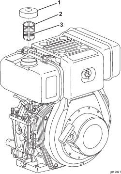
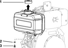
Remove the wing nut that secures the air-cleaner cover (Figure 20).
-
Remove the air-cleaner cover.
-
Remove the internal wing nut.
-
Remove the foam and paper elements from the base (Figure 20).
-
Remove the foam element from the paper element (Figure 20).
-
Inspect the foam and paper elements, and replace them if they are damaged or excessively dirty.
Note: Never try to brush dirt off the paper element; brushing forces the dirt into the fibers.
-
Wipe dirt from the base and the cover with a moist rag.
Note: Be careful to prevent dirt and debris from entering the air duct inside the air-cleaner housing.
-
Slide the outer foam element over the paper element.
-
Install the air cleaner elements and ensure that they are properly positioned.
-
Install the internal wing nut
-
Securely install the cover with the other wing nut.
Servicing the Engine Oil
| Maintenance Service Interval | Maintenance Procedure |
|---|---|
| After the first 25 hours |
|
| Every 100 hours |
|
Checking the Engine-Oil Level
| Maintenance Service Interval | Maintenance Procedure |
|---|---|
| Before each use or daily |
|
Important: Use 4-cycle engine oil that meets or exceeds the following guidelines and classifications:
-
API Service Categories CJ-4 or higher
-
ACEA Service Categories E-3, E-4, and E-5
Note: Toro Premium Engine Oil is available from your Authorized Toro Dealer.
Crankcase Capacity: 1.6 L (1.7 US qt)
Important: If the oil level in the crankcase is too low or too high and you run the engine, you may damage the engine. This type of damage is not covered by the warranty.
Viscosity: SAE 5W-30
Note: If the ambient temperature is above 35°C (95°F), use SAE 5W-40 or SAE 10W-40.
-
Place the machine on a flat, level surface.
-
Run the engine for a few minutes to warm the oil.
Note: Warm oil flows better and carries more contaminants.
-
Shut off the engine and wait for all moving parts to stop.
-
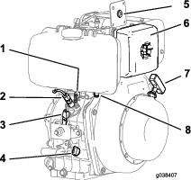
Clean around the dipstick (Figure 21) so that dirt cannot fall into the filler hole and damage the engine.
-
Remove the dipstick and wipe the end clean (Figure 21).
-
Slide the dipstick fully into the fill port without threading it into the port.
-
Remove the dipstick and look at the end.
Note: If the engine oil level is below the halfway point on the hatchmarks, slowly pour only enough oil into the fill port to raise the level to the halfway point on the dipstick.
-
Install the dipstick.
Changing the Engine Oil
-
Ensure that the machine is on a level surface.
-
Run the engine for a few minutes to warm the oil.
Note: Warm oil flows better and carries more contaminants.
-
Shut off the engine and wait for all moving parts to stop.
-
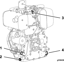
Place a suitable receptacle under the oil drain plug (Figure 22).
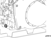
-
Remove the drain plug.
-
Allow the oil to drain and replace the drain plug.
-
Remove the dipstick (Figure 21) and slowly pour oil into the fill hole until the oil is between the upper and lower limit on the dipstick; refer to Checking the Engine-Oil Level.
-
Install and secure the dipstick.
-
Wipe up any spilled oil.
Inspecting and Cleaning the Engine-Oil Filter
| Maintenance Service Interval | Maintenance Procedure |
|---|---|
| After the first 50 hours |
|
| Every 400 hours |
|
-
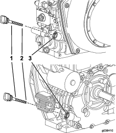
Remove the oil-filter retaining bolt.
-
Pull the oil-filter cap out and remove the oil filter.
-
Clean the oil filter or replace it if it is damaged.
-
Install the oil filter.
-
Make sure that the oil-filter cap is fully seated.
-
Install and tighten the oil-filter retaining bolt.
-
Add new engine oil; refer toServicing the Engine Oil.
-
Warm up the engine by running it for 5 minutes, and check for any engine oil leaks.
-
After the engine is warm, turn it off and let it sit for 10 minutes.
-
Check the engine oil level by fully inserting, but not screwing in, the dipstick.
-
Add engine oil as needed; refer to Servicing the Engine Oil.
Fuel System Maintenance
Servicing the Fuel System
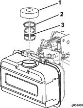
Cleaning the Inlet Fuel Screen
| Maintenance Service Interval | Maintenance Procedure |
|---|---|
| Every 50 hours |
|
-
Clean the area around the fuel cap.
-
Remove the fuel cap.
-
Lift the inlet fuel screen out of the fuel tank.
-
Clean the inlet fuel screen or replace it if it is damaged.
-
Install the inlet fuel screen.
-
Install the fuel cap and hand tighten it.
Note: Overtightening the fuel cap will damage it.
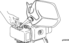
Draining the Fuel Tank and Replacing the Outlet Fuel Filter
| Maintenance Service Interval | Maintenance Procedure |
|---|---|
| Every 200 hours |
|
-
Shut off the engine and wait for all moving parts to stop.
-
Place an approved container under the fuel tank to collect the fuel.
-
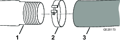
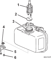
Remove the fuel cap (Figure 25).
-
Remove the drain plug and gasket to drain the fuel (Figure 25).
-
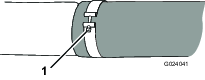
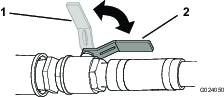
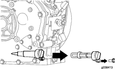
Loosen the nuts under the fuel-shutoff lever (Figure 26).
-
Remove and discard the O-ring (Figure 26).
-
Pull the outlet fuel filter and gasket out of the filler port (Figure 26).
-
Install a new outlet fuel filter and gasket through the filler port, and seat them in the fuel tank (Figure 26).
-
Install a new O-ring on the fuel shutoff lever, and install the assembly to the fuel tank using the nuts under the fuel shutoff lever (Figure 26).
-
Install the drain plug with a new gasket (Figure 25).
-
Install the fuel cap and hand tighten it.
Note: Overtightening the fuel cap will damage it.
Electrical System Maintenance
Replacing the Battery
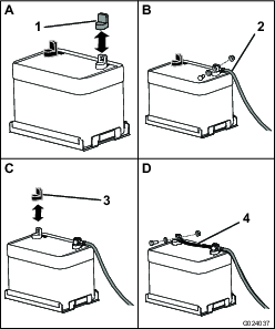
-
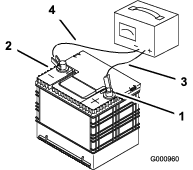
Remove the cover of the battery box.
-
Disconnect the negative (black) ground cable from the battery post.
Warning
Incorrect battery cable routing could damage the machine and cables, causing sparks. Sparks can cause the battery gases to explode, resulting in personal injury.
-
Always disconnect the negative (black) battery cable before disconnecting the positive (red) cable.
-
Always connect the positive (red) battery cable before connecting the negative (black) cable.
Warning
Battery terminals or metal tools could short against metal machine components, causing sparks. Sparks can cause the battery gases to explode, resulting in personal injury.
-
When removing or installing the battery, do not allow the battery terminals to touch any metal parts of the machine.
-
Do not allow metal tools to short between the battery terminals and metal parts of the machine.
-
-
Remove the positive (red) battery cable.
-
Remove the battery.
-
Place the new battery in the tray.
-
Install the positive (red) battery cable to the positive (+) battery terminal, and tighten the nut onto the bolt.
-
Install the negative (black) ground cable to the negative (-) battery terminal, and tighten the nut onto the bolt.
-
Install the cover of the battery box, and secure it with the strap.
-
Recycle the old battery at an authorized facility.
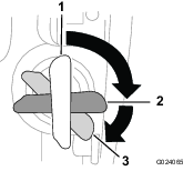
Charging the Battery
Warning
Charging the battery produces gases that can explode, seriously injuring you or bystanders.
Never smoke near the battery, and keep sparks and flames away from the battery.
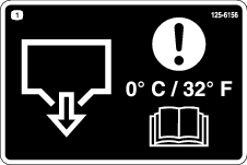
Important: Always keep the battery fully charged. This is especially important to prevent battery damage when the temperature is below 0°C (32°F).
-
Charge the battery for 10 to 15 minutes at 25 to 30 A, or 30 minutes at 10 A.
-
When the battery is fully charged, unplug the charger from the electrical outlet, and disconnect the charger leads from the battery posts (Figure 27).
-
Install the battery in the machine and connect the battery cables; refer to Connecting the Battery.
Important: Do not run the machine with the battery disconnected; electrical damage may occur.
If the battery no longer holds a charge, replace it; refer to Checking and Cleaning the Battery.
Checking and Cleaning the Battery
| Maintenance Service Interval | Maintenance Procedure |
|---|---|
| Every 100 hours |
|
Keep the top of the battery clean. If the machine is stored in a location where temperatures are extremely high, the battery discharges more rapidly than if the machine is stored in a cooler location.
Keep the top of the battery clean by washing it with a brush dipped in ammonia or a solution of sodium bicarbonate. Flush the top surface with water after cleaning. Do not remove the fill cap while cleaning the battery.
The battery cables must be tight on the terminals to provide good electrical contact.
If corrosion occurs at the battery terminals, disconnect the cables, negative (-) cable first, and scrape the clamps and terminals separately. Connect the cables, positive (+) cable first, and coat the terminals with petroleum jelly.
Cleaning
Cleaning the Machine
| Maintenance Service Interval | Maintenance Procedure |
|---|---|
| After each use |
|
Regular cleaning and washing increases the life span of the machine. Clean the machine after each use, before the dirt hardens.
Ensure that the fuel-tank cap and oil cap/dipstick are secure to avoid getting water in the engine.
Use care when using a high-pressure sprayer, because it can damage warning decals, instruction signs, and the engine.