| Maintenance Service Interval | Maintenance Procedure |
|---|---|
| Before each use or daily |
|
Introduction
This utility vehicle is intended to be primarily used off-highway to transport people and material loads.
Read this information carefully to learn how to operate and maintain your product properly and to avoid injury and product damage. You are responsible for operating the product properly and safely.
You may contact Toro directly at www.Toro.com for product safety and operation training materials, accessory information, help finding a dealer, or to register your product.
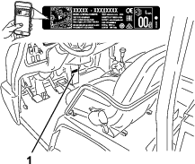
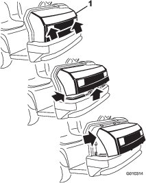
Whenever you need service, genuine Toro parts, or additional information, contact an Authorized Service Dealer or Toro Customer Service and have the model and serial numbers of your product ready. Figure 1 identifies the location of the model and serial numbers on the product. Write the numbers in the space provided.
Important: With your mobile device, you can scan the QR code on the serial number decal (if equipped) to access warranty, parts, and other product information.
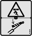
This manual identifies potential hazards and has safety messages identified by the safety-alert symbol (Figure 2), which signals a hazard that may cause serious injury or death if you do not follow the recommended precautions.

This manual uses 2 words to highlight information. Important calls attention to special mechanical information and Note emphasizes general information worthy of special attention.
This product complies with all relevant European directives; for details, please see the separate product specific Declaration of Conformity (DOC) sheet.
Warning
CALIFORNIA
Proposition 65 Warning
The engine exhaust from this product contains chemicals known to the State of California to cause cancer, birth defects, or other reproductive harm.
It is a violation of California Public Resource Code Section 4442 or 4443 to use or operate the engine on any forest-covered, brush-covered, or grass-covered land unless the engine is equipped with a spark arrester, as defined in Section 4442, maintained in effective working order or the engine is constructed, equipped, and maintained for the prevention of fire.
The enclosed engine owner's manual is supplied for information regarding the US Environmental Protection Agency (EPA) and the California Emission Control Regulation of emission systems, maintenance, and warranty. Replacements may be ordered through the engine manufacturer.
Safety
Improper use or maintenance by the operator or owner can result in injury. To reduce the potential for injury, comply with these safety instructions and always pay attention to the safety-alert symbol (Figure 2), which means Caution, Warning, or Danger—personal safety instruction. Failure to comply with the instruction may result in personal injury or death.
The machine meets the requirements of SAE J2258.
General Safety
This product is capable of causing personal injury. Always follow all safety instructions to avoid serious personal injury.
Using this product for purposes other than its intended use could prove dangerous to you and bystanders.
-
Read and understand the contents of this Operator’s Manual before you start the engine. Ensure that everyone using this product knows how to use it and understands the warnings.
-
Use your full attention while operating the machine. Do not engage in any activity that causes distractions; otherwise, injury or property damage may occur.
-
Do not put your hands or feet near moving components of the machine.
-
Do not operate the machine without all guards and other safety protective devices in place and working on the machine.
-
Keep the machine a safe distance away from bystanders while it is moving.
-
Keep children out of the operating area. Never allow children to operate the machine.
-
Stop the machine, shut off the engine, and remove the key before servicing or fueling.
Improperly using or maintaining this machine can result in injury. To reduce the potential for injury, comply with these safety instructions and always pay attention to the safety-alert symbol, which means Caution, Warning, or Danger—personal safety instruction. Failure to comply with these instructions may result in personal injury or death.
You can find additional safety information where needed throughout this manual.
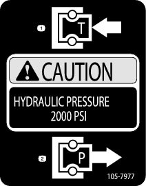
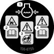
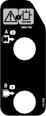
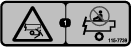
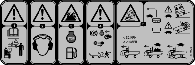
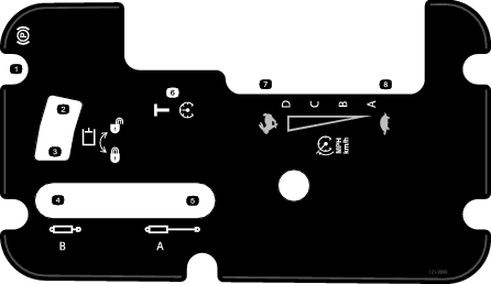
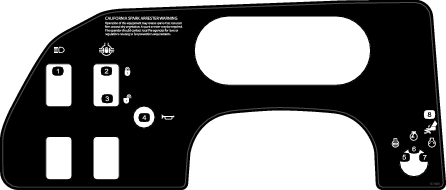
Safety and Instructional Decals
|
Safety decals and instructions are easily visible to the operator and are located near any area of potential danger. Replace any decal that is damaged or missing. |


Setup
Note: Determine the left and right side of the machine from the normal operating position.
Installing the Steering Wheel
TC and H Models Only
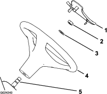
Parts needed for this procedure:
| Steering wheel | 1 |
| Cover | 1 |
| Washer (5/8 inch) | 1 |
-
If the cover is installed, remove it from the hub of the steering wheel (Figure 3).
-
Remove the nut from the steering shaft (Figure 3).
-
Slide the steering wheel and washer onto the steering shaft (Figure 3).
-
Secure the steering wheel to the shaft with the nut and tighten it to 27 to 34 N∙m (20 to 25 ft-lb).
-
Install the cover on the steering wheel (Figure 3).
Connecting the Battery
TC and H Models Only
Warning
Incorrectly routing the battery cable could damage the machine and cables, causing sparks. Sparks can cause the battery gasses to explode, resulting in personal injury.
-
Always disconnect the negative battery cable (black) before disconnecting the positive battery cable (red).
-
Always connect the positive battery cable (red) first.
-
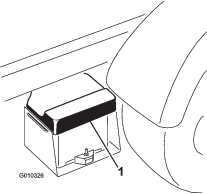
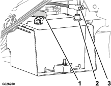
Squeeze the battery cover to release the tabs from the battery base (Figure 4).
-
Remove the battery cover from the battery base (Figure 4).
-
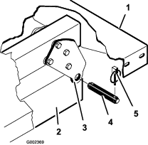
Connect the positive battery cable (red) to the positive (+) terminal of the battery and secure the cable with the bolts and nuts (Figure 5).
-
Slide the insulator boot over the positive terminal.
Note: The insulator boot prevents a possible short-to-ground from occurring.
-
Connect the negative battery cable (black) to the negative (–) terminal of the battery and secure the cable with bolts and nuts.
-
Align the battery cover to the battery base (Figure 4).
-
Squeeze the battery cover, align the tabs to the battery base, and release the battery cover (Figure 4).
Checking the Fluid Levels and Tire Pressure
-
Check the engine-oil level before and after you first start the engine; refer to Checking the Engine-Oil Level.
-
Check the transmission-fluid level before you first start the engine; refer to Checking the Transmission-Fluid Level.
-
Check the engine-coolant level before you first start the engine; refer to Checking the Engine-Coolant Level.
-
Check the brake-fluid level before you first start the engine; refer to Checking the Brake-Fluid Level.
-
Check the air pressure in the tires; refer to Checking the Tire Pressure.
Installing the Rollover Protection System (ROPS)
Parts needed for this procedure:
| ROPS frame | 1 |
| Flange-head bolt (1/2 x 1-1/4 inches) | 6 |
-
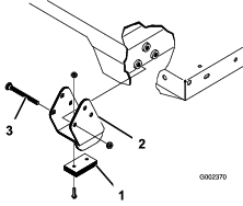
Apply medium-grade (service-removable) thread-locking compound to the threads of the 6 flange-head bolts (1/2 x 1-1/4 inches).
-
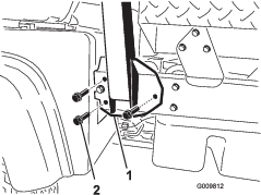
Align each side of the ROPS with the mounting holes on each side of the machine frame (Figure 6).
-
Secure the ROPS mounting bracket to the machine frame using 3 flange-head bolts (1/2 x 1-1/4 inches) on each side (Figure 6).
-
Torque the flange-head bolts (1/2 x 1-1/4 inches) to 115 N∙m (85 ft-lb).
Connecting the CVT-Intake Duct
Important: Remove the plastic bag covering the end of the CVT duct before starting the engine.
The CVT Kit (Part No. 121-9853) and Adapter Kit (Part No. 127-8750) are required for this procedure.
-
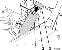
Loosen the hose clamp securing the plastic bag at the end of the CVT-intake hose and remove the bag.
-
Raise the cargo bed by performing the following:
-
Engage the parking brake.
-
Start the engine.
-
Move the hydraulic-lift lever rearward to raise the cargo box.
-
Shut off the engine.
-
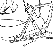
Remove the bed support from the storage brackets on the back of the ROPS panel and install the support onto the cylinder rod of the bed-lift cylinder; refer to Using the Bed Support.
-
-
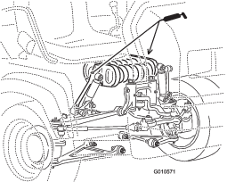
Align the CVT-intake hose onto the intake-tube connector at the back side of the ROPS panel and tighten the hose clamp (Figure 7).
-
Remove the bed support, lower the bed, shut off the engine, and remove the key.
Burnishing the Brakes
To ensure optimum performance of the brake system, burnish the brakes before use.
-
Bring the machine up to full speed, apply the brakes to rapidly stop the machine without locking up the tires.
-
Repeat this procedure 10 times, waiting 1 minute between stops, to avoid overheating the brakes.
Important: This procedure is most effective if the machine is loaded with 454 kg (1,000 lb).
Product Overview
Note: Determine the left and right sides of the machine from the normal operating position.
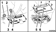
Accelerator Pedal
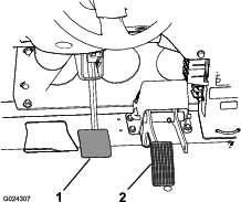
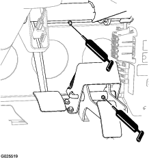
Use the accelerator pedal (Figure 8) to vary the ground speed of the machine when the transmission is in gear. Pressing down the accelerator pedal increases the engine speed and ground speed. Releasing the pedal decreases the engine speed and ground speed.
Brake Pedal
Use the brake pedal to stop or slow the machine (Figure 8).
Caution
Operating a machine with worn or incorrectly adjusted brakes can may result in personal injury.
If the brake pedal travels to within 25 mm (1 inch) of the machine floor board, adjust or repair the brakes.
Transmission Lever
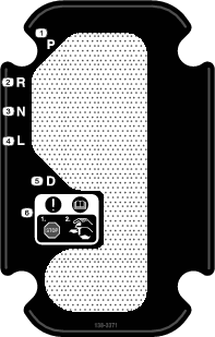
Use the transmission lever (Figure 9) to shift the transmission between (PARK), (REVERSE), (NEUTRAL), (LOW FORWARD), and (DRIVE) ground operation.
Important: Do not shift the transmission to the REVERSE, LOW, or DRIVE gear unless the machine is motionless and the engine is at low idle; otherwise, you could damage the transmission.
Parking-Brake Lever
Whenever you shut off the engine, engage the parking brake (Figure 10) to prevent the machine from accidentally moving. If the machine is parked on a steep grade, ensure that you engage the parking brake.
-
To engage the parking brake, pull back on the parking-brake lever.
-
To disengage the parking brake, push the parking-brake lever forward.
Note: Disengage the parking brake before moving the machine.
-
If you park the machine on a steep uphill or downhill grade, shift the transmission into (PARK) and engage the parking brake. Place chocks at the downhill side of the wheels.
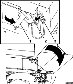
Hydraulic-Lift Lever
The hydraulic lift raises and lowers the bed. Move the hydraulic-lift lever rearward to raise the bed, and forward to lower it (Figure 11).
Important: When lowering the bed, hold the lever in the forward position for 1 to 2 seconds after the bed contacts the frame to secure it in the lowered position. Do not hold the hydraulic lift in the raise or lower position for more than 5 seconds, once the cylinders reach the end of their travel.
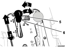
Hydraulic-Lift Lock
The hydraulic-lift lock secures the lift lever, so that the hydraulic cylinders do not operate when the machine is not equipped with a bed (Figure 11). It also locks the lift lever in the ON position when using the hydraulics for attachments.
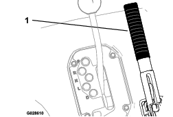
Speed-Range Lever
Use the speed-range lever (Figure 12) to select 1 of the 4 work-speed ranges for precise control of the maximum ground speed or a transport speed range for moving the machine between job sites.
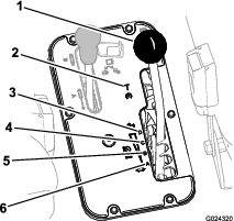
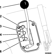
Control Panel
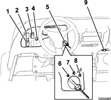
High-Flow Hydraulics Switch
TC Models Only
Push the switch down to start the high-flow hydraulics and push the switch up to shut off the hydraulics (Figure 13).
Note: You must set the high-flow hydraulics switch to the OFF position to start the engine.
Light Switch
Push the light switch (Figure 13) to toggle the headlights on or off.
Differential-Lock Switch
The differential-lock switch allows you to lock the rear axle for increased traction. Push the differential-lock switch (Figure 13) to toggle the differential lock on or off.
Note: You may lock and unlock the differential while the machine is in motion.
Horn Button
International Models Only
The horn button is located on the control panel (Figure 13). Press the horn button to sound the horn.
Key Switch
Use the key switch (Figure 13) to start and shut off the engine. To shut off the engine, rotate the key switch counterclockwise to the OFF position.
The key switch has 3 positions: OFF, RUN, and START. Rotate the key switch clockwise to the START position to engage the starter motor. Release the key switch when the engine starts. The key switch moves automatically to the ON position.
Power Point
Use the power point (Figure 13) to power optional 12 V electrical accessories.
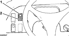
Instrument Cluster
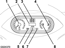
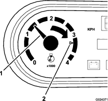
Tachometer
The tachometer displays the speed of the engine (Figure 14).
Note: The white triangle indicates the desired engine speed for 540 rpm PTO operation.
Hour Meter
The hour meter indicates the total hours of machine operation. The hour meter (Figure 14) starts to function whenever you rotate the key switch to the ON position or if the engine is running.
Speedometer
The speedometer registers the ground speed of the machine (Figure 14). The speedometer is in mph, but you can easily convert it to km/h; refer to Converting the Speedometer.
Check-Engine Light
The check-engine light (Figure 14) illuminates to notify the operator of an engine malfunction.
Contact your authorized Toro distributor.
Oil-Pressure-Warning Light
The oil-pressure-warning light (Figure 14) illuminates if the engine-oil pressure drops below a safe level while the engine is running.
Important: If the light flickers or remains on, stop the machine, shut off the engine, and check the oil level. If the oil level is low, but adding oil does not cause the light to go out when the engine is started, shut off the engine immediately, and contact your Authorized Service Dealer for assistance.
Check the operation of the warning lights as follows:
-
Engage the parking brake.
-
Turn the key switch to the ON/PREHEAT position, but do not start the engine.
Note: The oil-pressure light should glow red. If the light does not function, either a bulb is burned out or there is a malfunction in the system that you must repair.
Note: If engine was just shut off, it may take 1 to 2 minutes for the light to come on.
Coolant-Temperature Gauge and Light
The coolant-temperature gauge and light registers the coolant temperature in the engine and operates only when the key switch is in ON position (Figure 14). The indicator light blinks red if the engine overheats.
Fuel Gauge
The fuel gauge shows the amount of fuel in the tank. It displays only when key switch is in the ON position (Figure 14). The red segment of the display indicates a low-fuel level and the flashing red light indicates that the fuel in the tank is near empty.
Passenger Handhold
The passenger handhold is located on the dashboard (Figure 16).
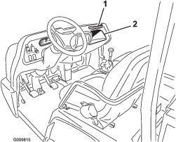
Seat-Adjustment Lever
You can adjust the seat forward and rearward for your comfort (Figure 17).
Note: Specifications and design are subject to change without notice.
| Overall width | 160 cm (63 inches) |
| Overall length | Without bed: 326 cm (128 inches) |
| With full bed: 331 cm (130 inches) | |
| With 2/3 bed in rear-mounting location: 346 cm (136 inches) | |
| Base weight (dry) | Model 07390: 866 kg (1,905 lb) |
| Model 07390H: 866 kg (1,905 lb) | |
| Model 07390TC: 887 kg (1,951 lb) | |
| Rated capacity (includes 91 kg (200 lb) operator, 91 kg (200 lb) passenger, and loaded attachment) | Model 07390: 1498 kg (3,295 lb) |
| Model 07390TC: 1477 kg (3,249 lb) | |
| Model 07090H: 1498 kg (3,298 lb) | |
| Maximum gross vehicle weight (GVW) | 2363 kg (5,210 lb) |
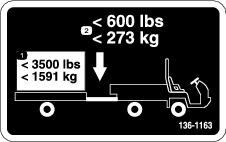
| Tow capacity | Tongue weight: 272 kg (600 lb) |
| Maximum trailer weight: 1587 kg (3,500 lb) | |
| Ground clearance | 18 cm (7 inches) with no load |
| Wheel base | 118 cm (70 inches) |
| Wheel tread (center line to center line) | Front: 117 cm (46 inches) |
| Rear: 121 cm (48 inches) | |
| Height | 191 cm (75 inches) to top of ROPS |
Attachments/Accessories
A selection of Toro approved attachments and accessories is available for use with the machine to enhance and expand its capabilities. Contact your Authorized Service Dealer or Distributor or go to www.Toro.com for a list of all approved attachments and accessories.
To ensure optimum performance and continued safety certification of the machine, use only genuine Toro replacement parts and accessories. Replacement parts and accessories made by other manufacturers could be dangerous, and such use could void the product warranty.
Operation
Before Operation
Before Operation Safety
General Safety
-
Never allow children or untrained people to operate or service the machine. Local regulations may restrict the age of the operator. The owner is responsible for training all operators and mechanics.
-
Become familiar with the safe operation of the equipment, operator controls, and safety signs.
-
Know how to stop the machine and shut off the engine quickly.
-
Ensure that you and your passengers do not exceed the number of handholds equipped on the machine.
-
Check that all safety devices and decals are in place. Repair or replace all safety devices and replace all illegible or missing decals. Do not operate the machine unless they are present and functioning properly.
Fuel Safety
-
Use extreme care in handling fuel. It is flammable and its vapors are explosive.
-
Extinguish all cigarettes, cigars, pipes, and other sources of ignition.
-
Use only an approved fuel container.
-
Do not remove the fuel cap or fill the fuel tank while the engine is running or hot.
-
Do not add or drain fuel in an enclosed space.
-
Do not store the machine or fuel container where there is an open flame, spark, or pilot light, such as on a water heater or other appliance.
-
If you spill fuel, do not attempt to start the engine; avoid creating any source of ignition until the fuel vapors have dissipated.
Performing Daily Maintenance
Before starting the machine each day, perform the Each Use/Daily procedures listed in .
Checking the Tire Pressure
Front tires air pressure specification: 220 kPa (32 psi)
Tear tires air pressure specification: 124 kPa (18 psi)
Important: Check the tire pressure frequently to ensure proper inflation. If the tires are not inflated to the correct pressure, the tires will wear prematurely and may cause the 4-wheel drive to bind.
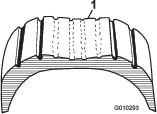
Figure 18 shows an example of tire wear caused by under-inflation.

Figure 19 shows an example of tire wear caused by over-inflation.
Adding Fuel
-
For best results, use only clean, fresh (less than 30 days old), unleaded gasoline with an cetane rating of 87 or higher ((R+M)/2 rating method).
-
Ethanol: Gasoline with up to 10% ethanol (gasohol) or 15% MTBE (methyl tertiary butyl ether) by volume is acceptable. Ethanol and MTBE are not the same. Gasoline with 15% ethanol (E15) by volume is not approved for use. Never use gasoline that contains more than 10% ethanol by volume, such as E15 (contains 15% ethanol), E20 (contains 20% ethanol), or E85 (contains up to 85% ethanol). Using unapproved gasoline may cause performance problems and/or engine damage which may not be covered under warranty.
-
Do not use gasoline containing methanol.
-
Do not store fuel either in the fuel tank or fuel containers over the winter unless you use a fuel stabilizer.
-
Do not add oil to gasoline.
Using Stabilizer/Conditioner
Use a fuel stabilizer/conditioner in the machine to provide the following benefits:
-
Keeps fuel fresh during storage of 90 days or less; for longer storage, drain the fuel tank
-
Cleans the engine while it runs
-
Eliminates gum-like varnish buildup in the fuel system, which causes hard starting
Important: Do not use fuel additives containing methanol or ethanol.
Add the correct amount of fuel stabilizer/conditioner to the fuel.
Note: A fuel stabilizer/conditioner is most effective when mixed with fresh fuel. To minimize the chance of varnish deposits in the fuel system, use fuel stabilizer at all times.
Filling the Fuel Tank
Fuel-tank capacity: 25 L (6.5 US gallons).
-
Clean the area around the fuel-tank cap.
-
Remove the fuel-tank cap (Figure 20).
-
Fill the tank to approximately 25 mm (1 inch) below the bottom of the filler neck, and install the cap.
Note: Do not overfill the fuel tank.
-
Wipe up any spilled fuel to prevent a fire hazard.
Breaking in a New Machine
| Maintenance Service Interval | Maintenance Procedure |
|---|---|
| After the first 100 hours |
|
Perform the following to provide proper performance for the machine:
-
Ensure that the brakes are burnished; refer to Burnishing the Brakes.
-
Check the fluid and engine-oil levels regularly. Remain alert for signs that the machine or its components are overheating.
-
After starting a cold engine, let it warm up for about 15 seconds before using the machine.
Note: Allow more time for the engine to warm up when operating in cold temperatures.
-
Vary the machine speed during operation. Avoid fast starts and quick stops.
-
A break-in oil for the engine is not required. Original engine oil is the same type specified for regular oil changes.
-
Refer to for any special, low-hour checks.
Checking the Safety-Interlock System
| Maintenance Service Interval | Maintenance Procedure |
|---|---|
| Before each use or daily |
|
The purpose of the safety-interlock system is to prevent the engine from cranking or starting, unless you press the clutch pedal.
Caution
If the safety-interlock switches are disconnected or damaged, the machine could operate unexpectedly, causing personal injury.
-
Do not tamper with the safety-interlock switches.
-
Check the operation of the safety-interlock switches daily, and replace any damaged switches before operating the machine.
Note: Refer to the attachment Operator’s Manual for procedures on checking the attachment interlock system.
Verifying the Clutch-Interlock Switch
-
Sit on the operator’s seat and engage the parking brake.
-
Move the shift lever to the NEUTRAL position.
Note: The engine does not start if the hydraulic-lift lever is locked in the forward position.
-
Without pressing the clutch pedal, rotate the key switch clockwise to the START position.
Note: If the engine cranks or starts, there is a malfunction in the interlock system that you must repair before operating the machine.
Verifying the Hydraulic-Lift Lever Safety-Interlock Switch
-
Sit on the operator’s seat and engage the parking brake.
-
Move the shift lever to the NEUTRAL position and ensure that the hydraulic-lift lever is in the center position.
-
Press the clutch pedal.
-
Move the hydraulic-lift lever forward and rotate the key switch to the START position.
Note: If the engine cranks or starts, there is a malfunction in the interlock system that you must repair before operating the machine.
During Operation
During Operation Safety
General Safety
-
The owner/operator can prevent and is responsible for accidents that may cause personal injury or property damage.
-
Passengers should sit in the designated seating positions only. Do not carry passengers in the cargo bed. Keep bystanders and pets away from the machine during operation.
-
Wear appropriate clothing, including eye protection; long pants; substantial, slip-resistant footwear; and hearing protection. Tie back long hair and do not wear loose jewelry.
-
Do not operate the machine while ill, tired, or under the influence of alcohol or drugs.
-
Operate the machine outdoors or in a well-ventilated area only.
-
Do not exceed the maximum gross vehicle weight (GVW) of the machine.
-
Use extra caution when operating the machine with a heavy load in the cargo bed. The heavier the load, the more difficult it is to turn or stop.
-
Carrying oversized loads in the cargo bed reduces the stability of the machine.
-
Carrying material that cannot be bound to the machine, such as a large tank of liquid, adversely affects the steering, braking, and stability of the machine.
-
Before you start the engine, ensure that the transmission is in neutral, the parking brake is engaged, and you are in the operating position.
-
You and your passengers should remain seated whenever the machine is moving. Keep your hands on the steering wheel; your passengers should use the handholds provided. Keep your arms and legs within the machine body at all times.
-
Operate the machine only in good visibility. Watch for holes, ruts, bumps, rocks, or other hidden objects. Uneven terrain could overturn the machine. Tall grass can hide obstacles. Use care when approaching blind corners, shrubs, trees, or other objects that may obscure your vision.
-
Always watch out for and avoid low overhangs such as tree limbs, door jambs, overhead walkways, etc.
-
Look behind and down before reversing the machine to be sure of a clear path.
-
Do not drive the machine near drop-offs, ditches, or embankments. The machine could suddenly roll over if a wheel goes over the edge or if the edge gives way.
-
When using the machine on public roads, follow all traffic regulations and use any additional accessories that may be required by law, such as lights, turn signals, slow-moving vehicle (SMV) signs, and others as required.
-
If the machine ever vibrates abnormally, stop the machine immediately, shut off the engine, remove the key, wait for all movement to stop, and inspect for damage. Repair all damage to the machine before resuming operation.
-
Carry a reduced load and reduce the ground speed of the machine when operating on rough, uneven terrain, and near curbs, holes, and other sudden changes in terrain. Loads may shift, causing the machine to become unstable.
-
It can take longer to stop the machine on wet surfaces than on dry surfaces. To dry out wet brakes, drive slowly on level ground while putting light pressure on the brake pedal.
-
Sudden changes in terrain may move the steering wheel unexpectedly, which could result in hand and arm injuries. Reduce your speed and grip the steering wheel loosely around the perimeter, keeping your thumbs out of the way of the steering wheel spokes.
-
Reduce the speed when you operate the machine with the cargo bed removed. Operating the machine at high speed and then quickly stopping may cause the rear wheels to lock up, which impairs your control of the machine.
-
Do not touch the engine, transmission, muffler, or muffler manifold while the engine is running, or soon after you shut off the engine, because these areas may be hot enough to cause burns.
-
Do not leave a running machine unattended.
-
Before leaving the operating position, do the following:
-
Park the machine on level ground.
-
Engage the parking brake.
-
Lower the cargo bed.
-
Shut off the engine and remove the key.
-
-
Do not operate the machine when there is the risk of lightning.
-
Use accessories and attachments approved by The Toro® Company only.
Rollover Protection System (ROPS) Safety
-
Do not remove the ROPS from the machine.
-
Ensure that the seat belt is attached and that you can release it quickly in an emergency.
-
Check carefully for overhead obstructions and do not contact them.
-
Keep the ROPS in safe operating condition by thoroughly inspecting it periodically for damage and keeping all the mounting fasteners tight.
-
Replace damaged ROPS components. Do not repair or alter them.
Machines with a Fixed Roll Bar
-
The ROPS is an integral safety device.
-
Always wear your seat belt.
Slope Safety
Slopes are a major factor related to loss-of-control and tip-over accidents, which can result in severe injury or death.
-
Survey the site to determine which slopes are safe for operating the machine and establish your own procedures and rules for operating on those slopes. Always use common sense and good judgment when performing this survey.
-
If you feel uneasy operating the machine on a slope, do not do it.
-
Keep all movement on slopes slow and gradual. Do not suddenly change the speed or direction of the machine.
-
Avoid operating the machine on wet terrain. Tires may lose traction. A rollover can occur before the tires lose traction.
-
Travel straight up and down a slope.
-
If you begin to lose momentum while climbing a slope, gradually engage the brakes and slowly reverse the machine straight down the slope.
-
Turning while going up or down a slope can be dangerous. If you must turn on a slope, do it slowly and cautiously.
-
Heavy loads affect stability on a slope. Carry a reduced load and reduce your ground speed when operating on a slope or if the load has a high center of gravity. Secure the load to the cargo bed of the machine to prevent the load from shifting. Take extra care when hauling loads that shift easily (e.g., liquids, rock, sand, etc.).
-
Avoid starting, stopping, or turning the machine on a slope, especially with a load. Stopping while going down a slope takes longer than stopping on level ground. If you must stop the machine, avoid sudden speed changes, which can cause the machine to tip or roll over. Do not engage the brakes suddenly when rolling rearward, as this may cause the machine to overturn.
Loading and Dumping Safety
-
Do not exceed the gross vehicle weight (GVW) of the machine when operating it with a load in the cargo bed and/or towing a trailer; refer to Specifications.
-
Distribute the load in the cargo bed evenly to improve the stability and control of the machine.
-
Before dumping, ensure that there is no one behind the machine.
-
Do not dump a loaded cargo bed while the machine is sideways on a slope. The change in weight distribution may cause the machine to overturn.
Operating the Cargo Bed
Raising the Cargo Bed
Warning
A raised bed could fall and injure persons that are working beneath it.
-
Always use the prop rod to hold the bed up before working under the bed.
-
Remove any load material from the bed before raising it.
Warning
Driving the machine with the cargo bed raised could cause the machine to tip or roll easier. You could damage the structure of the cargo bed if you operate the machine with the bed raised.
-
Operate the machine when the cargo bed is down.
-
After emptying the cargo bed, lower it.
Caution
If a load is concentrated near the back of the cargo bed when you release the latches, the bed may unexpectedly tip open, injuring you or bystanders.
-
Center loads in the cargo bed, if possible.
-
Hold the cargo bed down and ensure that no one is leaning over the bed or standing behind it when releasing the latches.
-
Remove all cargo from the bed before lifting the bed up to service the machine.
Move the lever rearward to raise the cargo bed (Figure 21).
Lowering the Cargo Bed
Warning
The weight of the bed may be heavy. Hands or other body parts could be crushed.
Keep your hands and other body parts away when lowering the bed.
Move the lever forward to lower the cargo bed (Figure 21).
Opening the Tailgate
-
Ensure that the cargo bed is down and latched.
-
Open the latches on the left and right side of the cargo bed and lower the tailgate (Figure 22).
Starting the Engine
Important: Do not attempt to push or tow the machine to get it started. Damage to the drive train could result.
-
Sit on the operator seat and engage the parking brake.
-
Disengage the PTO and the high-flow hydraulics (if equipped) and move the hand-throttle lever to the OFF position (if equipped).
-
Move the transmission lever to the (PARK) position.
-
Ensure that the hydraulic-lift lever is in the OFF position (center).
-
Press the brake pedal.
Note: Keep your foot off the accelerator pedal.
-
Insert the key into the key switch and rotate it clockwise to start the engine.
Note: Release the key switch when the engine starts.
Note: The oil-pressure warning light should turn off.
Important: To prevent overheating of the starter motor, do not engage starter longer than 15 seconds. After 15 seconds of continuous cranking, wait 60 seconds before engaging starter motor again.
Driving the Machine
-
Press the brake pedal.
-
Disengage the parking brake.
-
Move the transmission lever to the desired gear.
-
Release the service brake and gradually press in the accelerator pedal.
Important: Always stop the machine before shifting to reverse a forward gear or to a forward gear from reverse.
Use the chart below to determine the ground speed of each gear when operating the machine with the speed-range control in the (TRANSPORT) position.
Gear Speed (km/h) Speed (mph) (REVERSE) 0 to 21 0 to 13 (LOW FORWARD) 0 to 18 0 to 11 (DRIVE) 0 to 32 0 to 20 Note: Avoid idling the engine for long periods of time.
Note: Leaving the key switch in the ON position for long periods of time without starting the engine discharges the battery.
Stopping the Machine
To stop the machine, remove your foot from the accelerator pedal, then press the brake pedal.
Shutting Off the Engine
-
Stop the machine.
-
Move the transmission lever to the (PARK) position.
-
Engage the parking brake.
-
Rotate the key switch to the OFF position and remove the key.
Using the Speed-Range Control
Use the lever of the speed-range control to limit the maximum ground speed of the machine for operations that require a constant speed like spraying and top dressing. The speed-range lever (Figure 23) is used to select 1 of the 4 work-speed ranges that are used to limit maximum ground speed or a transport-speed range that is used when you move the machine between job sites.
Note: You must release the accelerator pedal in order to shift between speed ranges, but you do not need to stop the machine in order to shift.
-
Move the speed-range lever into the detent for speed ranges A, B, C, and D when precise control of maximum-ground speed is desired.
-
Move the speed-range lever to the T (TRANSPORT) position by moving the speed-range lever out of the detent for range A, B, C, or D, then forward to the T (TRANSPORT) position.
Note: Use the speed-range control to limit the maximum ground speed in each range by 4 to 18 km/h (2.5 to 11 mph) with the transmission lever in the (LOW FORWARD) position or 8 to 32 km/h (5 to 20 mph) with the transmission lever in the in the (DRIVE) position.
Using the Differential Lock
Warning
Tipping or rolling the machine on a hill can cause a serious injury.
-
The extra traction available with the differential lock can be enough to get you into dangerous situations such as climbing slopes that are too steep to turn around. Be extra careful when operating with the differential lock on, especially on steeper slopes.
-
If the differential lock is on when making a sharp turn at a higher speed and the inside rear wheel lifts off the ground, there may be a loss of control, which could cause the machine to skid. Use the differential lock only at slower speeds.
Caution
Turning with the differential lock on can result in loss of machine control. Do not operate with differential lock on when making sharp turns or at high speeds.
The differential lock increases the traction of the machine by locking the rear wheels so that a wheel does not spin out. This can help when you have heavy loads to haul, on wet turf or slippery areas, going up hills, and on sandy surfaces. It is important to remember that this extra traction is only for temporary, limited use. Its use does not replace the safe operation already discussed concerning steep hills and heavy loads.
The differential lock causes the rear wheels to spin at the same speed. When using the differential lock, your ability to make sharp turns is somewhat restricted and may scuff the turf. Use the differential lock only when needed and at slower speeds.
Note: Machine motion plus a slight turn is required to engage or disengage differential lock.
-
Press the differential-lock switch up to lock the differential (Figure 24).
Note: The light in the differential-lock switch illuminates when the switch is in the lock position.
-
Press the differential-lock switch up to unlock the differential (Figure 24).
Using the Hydraulic Control
The hydraulic control supplies hydraulic power from the machine pump whenever the engine runs. You can use the power through the quick couplers at the rear of the machine.
Warning
Hydraulic fluid escaping under pressure can have sufficient force to penetrate skin and can cause serious injury.
Use care when connecting or disconnecting hydraulic quick couplers. Shut off the engine, engage the parking brake, lower the attachment, and place the remote hydraulic valve in the float detent position to relieve the hydraulic pressure before connecting or disconnecting the quick couplers.
Important: If multiple machines use the same attachment, cross-contamination of the transmission fluid may occur. Change the transmission fluid more frequently.
Using the Hydraulic Bed-Lift Lever to Control Hydraulic Attachments
-
OFF Position
This is the normal position for the control valve when it is not in use. In this position, the work ports of the control valve are blocked and any load is held by the check valves in both directions.
-
RAISE (Quick Coupler A) Position
This position lifts the bed and rear hitch attachment, or applies pressure to quick coupler A. This position also allows hydraulic fluid to return from quick coupler B to flow back into the valve and then out to the reservoir. This is a momentary position, and when you release the lever, it spring-returns to the center, OFF position.
-
LOWER (Quick Coupler B) Position
This position lowers the bed, rear hitch attachment, or applies pressure to quick coupler B. This also allows hydraulic fluid to return from quick coupler A to flow back into the valve and then out to the reservoir. This is a momentary position, and when you release the lever, it spring-returns to the center, OFF position. Momentarily holding and then releasing the control lever in this position provides hydraulic-fluid flow to quick coupler B, which provides power down on the rear hitch. When you release it, it holds the down-pressure on the hitch.
Important: If you use it with a hydraulic cylinder, holding the control lever in the lower position causes the hydraulic-fluid flow to go over a relief valve, which can damage the hydraulic system.
-
ON Position
This position is similar to the LOWER (QUICK COUPLER B POSITION). It also directs hydraulic fluid to quick coupler B, except that the lever is held in this position by a detent lever in the control panel. This allows hydraulic fluid to flow continuously to equipment that use a hydraulic motor.
Use this position only on attachments with a hydraulic motor attached.
Important: If you use it with a hydraulic cylinder or no attachment, the ON position causes the hydraulic-fluid flow to go over a relief valve, which can damage the hydraulic system. Use this position only momentarily or with a motor attached.
Important: Check the hydraulic-fluid level after installation of an attachment. Check the operation of the attachment by cycling the attachment several times to purge air from the system, then check hydraulic-fluid level again. The attachment cylinder slightly affects the fluid level in the transaxle. Operating the machine with a low hydraulic-fluid level can damage the pump, remote hydraulics, power steering, and machine transaxle.
Connecting the Quick Couplers
Important: Clean dirt from the quick couplers before connecting them. Dirty couplers can introduce contamination into the hydraulic system.
-
Pull back the locking ring on the coupler.
-
Insert the hose nipple into the coupler until it snaps into position.
Note: When attaching remote equipment to the quick couplers, determine which side requires pressure, then attach that hose to quick coupler B, which has pressure when you push the control lever forward or locked in the ON position.
Disconnecting the Quick Couplers
Note: With both the machine and attachment shut off, move the lift lever back and forth to remove the system pressure and ease the disconnection of the quick couplers.
-
Pull back the locking ring on the coupler.
-
Pull the hose firmly from the coupler.
Important: Clean and install the dust plug and dust covers to the quick coupler ends when not in use.
Troubleshooting the Hydraulic Control
-
Difficulty in connecting or disconnecting quick couplers.
The pressure is not relieved (the quick coupler is under pressure).
-
The power steering is turning with great difficulty or it is not turning at all.
-
The hydraulic-fluid level is low.
-
The hydraulic-fluid temperature is too hot.
-
The pump is not operating.
-
-
There are hydraulic leaks.
-
The fittings are loose.
-
The fitting is missing the O-ring.
-
-
An attachment does not function.
-
The quick couplers are not fully engaged.
-
The quick couplers are interchanged.
-
-
There is a squealing noise.
-
Remove the valve left in the ON position detent, causing hydraulic fluid to flow over the relief valve.
-
The belt is loose.
-
-
The engine does not start.
The hydraulic lever is locked in the FORWARD position.
After Operation
After Operation Safety
General Safety
-
Allow the engine to cool before storing the machine in any enclosure.
-
Do not store the machine or fuel container where there is an open flame, spark, or pilot light, such as on a water heater or other appliance.
-
Keep all parts of the machine in good working condition and all hardware tightened.
-
Replace all worn, damaged, or missing decals.
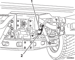
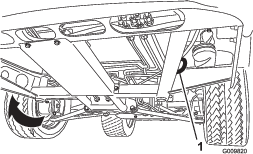
Transporting the Machine
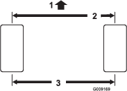
-
Use care when loading or unloading the machine into a trailer or a truck.
-
Use full-width ramps for loading the machine into a trailer or a truck.
-
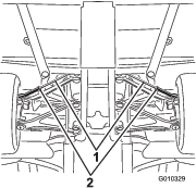
Tie the machine down securely.
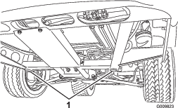
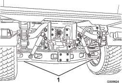
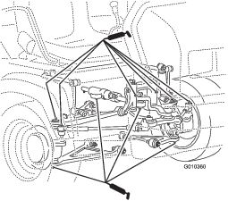
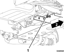
Refer to Figure 26 and Figure 27 for the tie-down locations on the machine.
Note: Load the machine on the trailer with the front of the machine facing forward. If that is not possible, secure the machine hood to the frame with a strap, or remove the hood and transport and secure it separately; otherwise, the hood may blow off during transport.
Towing the Machine
In case of an emergency, you can tow the machine for a short distance; however, this is not the standard operating procedure.
Warning
Towing at excessive speeds could cause a loss of steering control, resulting in personal injury.
Never tow the machine at faster than 8 km/h (5 mph).
Note: The power steering does not function, making it difficult to steer.
Towing the machine is a 2-person job. If you must move the machine a considerable distance, transport it on a truck or trailer.
-
Affix a tow line to the tongue at the front of the frame of the machine (Figure 26).
-
Move the transmission to the NEUTRAL position and disengage the parking brake.
Towing a Trailer
The machine is capable of pulling trailers and attachments of greater weight than the machine itself. Several types of tow hitches are available for the machine, depending on your application. Contact your Authorized Service Dealer for details.
When equipped with a tow hitch bolted onto the rear axle tube, your machine can tow trailers or attachments with a maximum gross trailer weight (GTW) up to 1587 kg (3,500 lb).
Always load a trailer with 60% of the cargo weight in the front of the trailer. This places approximately 10% (272 kg (600 lb) maximum) of the gross trailer weight (GTW) on the tow hitch of the machine.
When hauling cargo or towing a trailer (attachment), do not overload the machine or trailer. Overloading can cause poor performance or damage to the brakes, axle, engine, transaxle, steering, suspension, body structure, or tires.
Important: To reduce potential for drive line damage, use low range.
When towing fifth-wheel attachments, like a fairway aerator, always install the wheel bar (included with the fifth wheel kit) to prevent the front wheels from lifting off the ground if the towed attachments movement is suddenly impaired.
Maintenance
Note: Determine the left and right sides of the machine from the normal operating position.
Note: Download a copy of the electrical schematic by visiting www.Toro.com and searching for your machine from the Manuals link on the home page.
Important: Refer to your engine owner’s manual for additional maintenance procedures.
Warning
Failure to properly maintain the machine could result in premature failure of machine systems causing possible harm to you or bystanders.
Keep the machine well maintained and in good working order as indicated in these instructions.
Caution
Only qualified and authorized personnel should maintain, repair, adjust, or inspect the machine.
-
Avoid fire hazards and have fire-protection equipment present in the work area. Do not use an open flame to check fluid levels or leakage of fuel, battery electrolyte, or coolant.
-
Do not use open pans of fuel or flammable cleaning fluids for cleaning parts.
Caution
If you leave the key in the key switch, someone could accidently start the engine and seriously injure you or other bystanders.
Remove the key from the key switch and disconnect the wires from the spark plugs before you do any maintenance. Set the wires aside so that they do not accidentally contact the spark plugs.
Recommended Maintenance Schedule(s)
| Maintenance Service Interval | Maintenance Procedure |
|---|---|
| After the first 2 hours |
|
| After the first 10 hours |
|
| After the first 50 hours |
|
| After the first 100 hours |
|
| Before each use or daily |
|
| Every 25 hours |
|
| Every 50 hours |
|
| Every 100 hours |
|
| Every 200 hours |
|
| Every 400 hours |
|
| Every 800 hours |
|
| Every 1,000 hours |
|
| Yearly |
|
Maintaining the Machine under Special Operating Conditions
Important: If the machine is subjected to any of the conditions listed below, perform maintenance twice as frequently:
-
Desert operation
-
Cold climate operation—below 10°C (50°F)
-
Trailer towing
-
Frequent operation in dusty conditions
-
Construction work
-
After extended operation in mud, sand, water, or similar dirty conditions, have your brakes inspected and cleaned as soon as possible. This prevents any abrasive material from causing excessive wear.
Pre-Maintenance Procedures
Many of the subjects covered in this maintenance section require raising and lowering the bed. To prevent serious injury or death, take the following precautions.
Maintenance Safety
-
Do not allow untrained personnel to service the machine.
-
Before servicing or making any adjustments to the machine, park the machine on a level surface, engage the parking brake, shut off the engine, and remove the key to prevent accidental starting of the machine.
-
Use jack stands to support the machine or components when required.
-
Carefully release pressure from components with stored energy.
-
Do not charge the batteries while servicing the machine.
-
To ensure that the entire machine is in good condition, keep all the nuts, bolts, and screws properly tightened.
-
To reduce the potential fire hazard, keep the engine area free of excessive grease, grass, leaves, and accumulation of dirt.
-
If possible, do not perform maintenance while the engine is running. Keep away from moving parts.
-
If you must run the engine to perform a maintenance adjustment, keep your hands, feet, clothing, and any parts of the body away from the engine and any moving parts. Keep bystanders away from the machine.
-
Clean up oil and fuel spills.
-
Check the parking brake operation frequently. Adjust and service as required.
-
Keep all parts in good working condition and all hardware tightened. Replace all worn or damaged decals.
-
Never interfere with the intended function of a safety device or reduce the protection provided by a safety device. Check their proper operation regularly.
-
Do not overspeed the engine by changing the governor settings. To ensure safety and accuracy, have an authorized Toro distributor to check the maximum engine speed with a tachometer.
-
If major repairs are ever necessary or assistance is required, contact an authorized Toro distributor.
-
Altering this machine in any manner may affect the operation of the machine, performance, durability, or its use may result in injury or death. Such use could void the product warranty of The Toro® Company.
Preparing the Machine for Maintenance
-
Park the machine on a level surface.
-
Engage the parking brake.
-
Shut off the engine and remove the key.
-
Empty and raise the cargo bed; refer to Raising the Cargo Bed.
Using the Bed Support
Important: Always install or remove the bed support from the outside of the bed.
-
Raise the bed until the lift cylinders are fully extended.
-
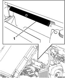
Remove the bed support from the storage brackets on the back of the ROPS panel (Figure 28).
-
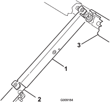
Push the bed support onto the cylinder rod, and ensure that the support-end tabs rest on the end of the cylinder barrel and cylinder-rod end (Figure 29).
-
Remove the bed support from the cylinder, and insert it into the brackets on the back of the ROPS panel.
Important: Do not try to lower the bed with the bed-safety support on the cylinder.
Removing the Full Bed
-
Start the engine, engage the hydraulic-lift lever, and lower the bed until the cylinders are loose in the slots.
-
Release the lift lever and shut off the engine.
-
Remove the lynch pins from the outer ends of the cylinder rod clevis pins (Figure 30).
-
Remove the clevis pins securing the cylinder rod ends to the bed-mounting plates by pushing the pins toward the inside (Figure 30).
-
Remove the lynch pins and clevis pins securing the pivot brackets to the frame channels (Figure 30).
-
Lift the bed off the machine.
Caution
The full bed weighs approximately 148 kg (325 lb), so do not try to install or remove it by yourself.
Use an overhead hoist or get the help of 2 or 3 other people.
-
Store the cylinders in the storage clips.
-
Engage the hydraulic lift-lock lever on the machine to prevent accidental extension of the lift cylinders.
Installing the Full Bed
Note: If you are installing the bed sides on the flat bed, it is easier to install them before installing the bed on the machine.
Ensure that the rear pivot plates are bolted to the bed frame/channel so that the lower end angles to the rear (Figure 31).
Caution
The full bed weighs approximately 148 kg (325 lb), so do not try to install or remove it by yourself.
Use an overhead hoist or get the help of 2 or 3 other people.
Ensure that the spacer brackets and wear blocks (Figure 32) are installed with the carriage-bolt heads positioned inside the machine.
-
Ensure that the lift cylinders are fully retracted.
-
Carefully set the bed onto the machine frame, aligning the rear bed pivot-plate holes with the holes in the rear frame channel, and install the 2 clevis pins and lynch pins (Figure 32).
-
With the bed lowered, secure each cylinder rod end to the appropriate slots in the bed-mounting plates with a clevis pin and lynch pin.
-
Insert the clevis pin from outside of the bed with the lynch pin oriented toward the outside (Figure 32).
Note: The rear slots are for a full bed installation; the front slots are for a 2/3-full bed installation.
Note: You may need to start the engine to extend or retract the cylinders for alignment with the holes.
Note: You can plug the unused slot with a bolt and nut to prevent assembly errors.
-
Start the engine and engage the hydraulic-lift lever to raise the bed.
-
Release the lift lever and shut off the engine.
-
Install the bed-safety support to prevent accidentally lowering the bed; refer to Using the Bed Support.
-
Install the lynch pins to the inside ends of the clevis pins.
Note: If the automatic tailgate release is installed on the bed, ensure that the front dump link rod is placed on the inside of the left clevis pin before you install the lynch pin.
Raising the Machine
Danger
A machine on a jack may be unstable and slip off the jack, injuring anyone beneath it.
-
Do not start the machine while the machine is on a jack, as the engine vibration or wheel movement could cause the machine to slip off the jack.
-
Always remove the key from the key switch before getting off the machine.
-
Block the tires when the machine is on a jack.
When jacking up the front of the machine, always place a wooden block (or similar material) between the jack and the machine frame.
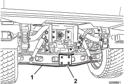
The jacking point at the front of the machine is located under the front, center frame support (Figure 33).
The jacking point at the rear of the machine is located under the axle (Figure 34).
Removing and Installing the Hood
Removing the Hood
-
While grasping the hood in the headlight openings, lift up the hood to release the lower mounting tabs from the frame slots (Figure 35).
-
Pivot the bottom of the hood upward until you can pull the top mounting tabs from the frame slots (Figure 35).
-
Pivot the top of the hood forward and unplug the wire connectors from the headlights (Figure 35).
-
Remove the hood.
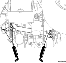
Lubrication
Greasing the Bearings and the Bushings
| Maintenance Service Interval | Maintenance Procedure |
|---|---|
| Every 100 hours |
|
Grease Type: No. 2 lithium grease
Important: When greasing the drive shaft universal shaft bearing crosses, pump grease until it comes out of all 4 cups at each cross.
-
Use a rag to wipe the grease fitting clean so that foreign matter cannot be forced into the bearing or bushing.
-
With a grease gun, apply grease into the grease fittings on the machine.
-
Wipe any excess grease off the machine.
The grease fitting locations and quantities are as follows:
-
Ball joints (4); refer to Figure 36
-
Pivot mounts (2); refer to Figure 36
-
Steering cylinder (2); refer to Figure 36
-
Tie rods (2); refer to Figure 36
-
Spring tower (2); refer to Figure 37
-
Brake (1); refer to Figure 38
-
Throttle (1); refer to Figure 38
-
Drive shaft U-joints (2); refer to Figure 39
-
Sliding yolk (1); refer to Figure 39
Engine Maintenance
Engine Safety
-
Shut off the engine, remove the key, and wait for all moving parts to stop before checking the oil or adding oil to the crankcase.
-
Keep your hands, feet, face, clothing, and other body parts away from the muffler and other hot surfaces.
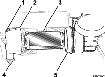
Servicing the Air Filter
| Maintenance Service Interval | Maintenance Procedure |
|---|---|
| Every 25 hours |
|
| Every 100 hours |
|
Inspect the air filter and hoses periodically to maintain maximum engine protection and to ensure maximum service life. Check the air-filter cover and housing for damage, which could cause an air leak. Replace any damaged air-filter components.
-
Pull the latch outward and rotate the air-filter cover counterclockwise (Figure 40).
-
Before removing the filter, use low-pressure air (40 psi, clean and dry) to remove large accumulations of debris packed between the outside of the air filter and the air-filter housing.
Important: Avoid using high-pressure air, which could force dirt through the filter into the intake tract. This cleaning process prevents debris from migrating into the intake when the primary filter is removed.
-
Remove the air filter from the housing (Figure 40).
Note: Do not clean a used filter element because you may damage the filter media.
-
Wipe clean the interior of the air-filter cover and housing (Figure 40).
-
Remove the rubber dust valve from the cover (Figure 40).
-
Clean the dirt-ejection port located in the air-cleaner cover, the dust-valve cavity, and replace the dust valve (Figure 40).
-
Inspect the new air filter for shipping damage, checking the sealing end of the filter and the body.
Important: Do not use a damaged element.
-
Insert the new air filter by applying light pressure to the outer rim of the filter to seat it in the air-filter housing (Figure 40).
-
Align the air-filter cover with the dust valve at the 6 o’clock position when viewed from the left end of the cover (Figure 40).
-
Secure the latch of the air-filter cover (Figure 40).
Note: Reset the indicator if it shows red (if equipped).
Servicing the Engine Oil
Note: Change the oil more frequently when operating conditions are extremely dusty or sandy.
Note: Dispose of the used engine oil and oil filter at a certified recycling center.
Engine-Oil Specifications
Oil Type: Detergent engine oil (API SJ or higher)
Crankcase Capacity: 2.0 L (2.1 US qt) when the filter is changed
Viscosity: See the table below.

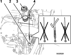
Checking the Engine-Oil Level
| Maintenance Service Interval | Maintenance Procedure |
|---|---|
| Before each use or daily |
|
Note: The best time to check the engine oil is when the engine is cool before it has been started for the day. If the engine has already ran, shut it off and wait for at least 10 minutes before checking the oil level.
-
Park the machine on a level surface.
-
Engage the parking brake.
-
Shut off the engine and remove the key.
-
Remove the dipstick and wipe it with a clean rag (Figure 42).
-
Insert the dipstick into the tube and ensure that it seats fully.
-
Remove dipstick and check the oil level (Figure 42).
-
If the oil level is low, remove the filler cap (Figure 42) and add enough oil to raise the level to the Full mark on the dipstick.
Note: When adding oil, remove dipstick to allow proper venting. Slowly pour the oil into the filler neck, and check the level often during this process. Do not overfill the engine with oil.
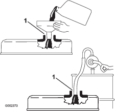
Important: When adding engine oil or filling oil, there must be clearance between the oil fill device and the oil fill neck in the valve cover as shown in Figure 43. This clearance is necessary to permit venting when adding oil.
-
Install the filler cap onto the filler neck (Figure 42).
-
Firmly install the dipstick (Figure 42).
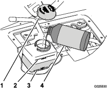
Changing the Engine Oil and Filter
| Maintenance Service Interval | Maintenance Procedure |
|---|---|
| After the first 50 hours |
|
| Every 200 hours |
|
-
Raise the bed and place the safety support on the extended lift cylinder to hold up the bed.
-
Align a large drain pan under the oil-drain plug (Figure 44).
-
Remove the drain plug and let the oil flow into a drain pan (Figure 44).
-
When the oil stops draining, install the drain plug.
-
Remove the oil filter from the filter adapter (Figure 45).
-
Wipe clean the sealing base of the of the filter adapter (Figure 45).
-
Apply a light coat of clean oil to the seal of the new filter.
-
Install the filter until the gasket contacts the sealing base of the filter adapter, then tighten the filter clockwise and additional 1/2 to 2/3 of a turn (Figure 45).
Note: Do not overtighten the engine-oil filter.
-
Add the specified oil to the crankcase of the engine.
Checking the Oil-Pressure-Warning Light
| Maintenance Service Interval | Maintenance Procedure |
|---|---|
| Before each use or daily |
|
Note: If you just shut off the engine, it may take 1 to 2 minutes for the light to come on.
-
Engage the parking brake.
-
Turn the key switch to the ON position, but do not start the engine.
Note: The oil-pressure light should glow red.
Note: If the light does not function, either a bulb is burned out, or there is a malfunction in the system that you must repair.
Servicing the Spark Plugs
| Maintenance Service Interval | Maintenance Procedure |
|---|---|
| Every 100 hours |
|
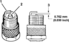
Type: Champion RN14YC (or equivalent)
Air Gap: 0.762 mm (0.03 inch)
Important: A cracked, fouled, dirty, or malfunctioning spark plug must be replaced. Do not sand-blast, scrape, or clean electrodes by using a wire brush because grit may eventually release from the plug and fall into the cylinder. The result is usually a damaged engine.
Note: The plug should be removed and checked whenever the engine malfunctions.
-
Clean the area around the spark plug so that foreign matter cannot fall into the cylinder when you remove the spark plug.
-
Pull the wire off the terminal of the spark plug.
-
Remove the plug from the cylinder head.
-
Check the condition of the side electrode, center electrode, and center electrode insulator to ensure that there is no damage (Figure 46).
Note: Do not use a damaged or worn spark plug. Replace it with a new spark plug of the specified type.
-
Set the air gap between the center and side of the electrodes at 0.762 mm (0.030 inch) as shown in Figure 46.
-
Install the spark plug into the cylinder head, and torque the plug to 20 N∙m (14.7 ft-lb).
-
Install the spark-plug wire.
-
Repeat steps 1 through 7 for the other spark plug.
Fuel System Maintenance
Inspecting the Carbon Canister Air Filter
| Maintenance Service Interval | Maintenance Procedure |
|---|---|
| After the first 50 hours |
|
| Every 200 hours |
|
-
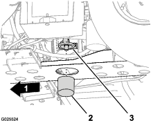
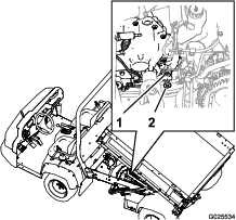
Locate the air filter on the bottom of the carbon canister (Figure 47).
-
Ensure that the opening on the bottom of the filter is clear and open.
-
Remove and install the new filter (if necessary).
Replacing the Fuel Filter
| Maintenance Service Interval | Maintenance Procedure |
|---|---|
| Every 400 hours |
|
-
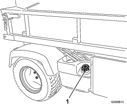
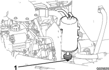
Raise the bed and place the safety support on the extended-lift cylinder to hold up the bed.
-
Unplug the wire-harness connectors from the fuel pump (Figure 48).
-
Loosen the hose clamp and disconnect the fuel line from the fuel-pump cap (Figure 48).
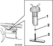
-
Remove the fuel-pump cap from the top of the fuel tank (Figure 48).
Important: Do not allow the fuel-pump assembly to rotate in the tank while removing the fuel pump. Damage to the float assembly can occur if the fuel pump rotates inside the fuel tank.
-
Remove the fuel-pump assembly and the fuel filter from the tank (Figure 48).
-
Remove the clamp securing the fuel filter hose to the fuel-pump fitting.
-
Remove the hose from the fitting (Figure 48).
-
Insert the new hose clamp onto the new fuel-filter hose.
-
Insert the hose onto the fuel pump and secure the clamp.
-
Insert the assembly into the fuel tank, and tighten the cap to 20 to 22 N∙m (175 to 200 in-lb).
-
Connect the wires and secure the hose with the hose clamp.
Inspecting Fuel Lines and Connections
| Maintenance Service Interval | Maintenance Procedure |
|---|---|
| Every 400 hours |
|
Inspect the fuel lines, fittings, and clamps for signs of leaking, deterioration, damage, or loose connections.
Note: Repair any damaged or leaking fuel system component before using the machine.
Electrical System Maintenance
Electrical System Safety
Warning
Battery posts, terminals, and related accessories contain lead and lead compounds, chemicals known to the State of California to cause cancer and reproductive harm. Wash hands after handling.
-
Disconnect the battery before repairing the machine. Disconnect the negative terminal first and the positive last. Connect the positive terminal first and the negative last.
-
Charge the battery in an open, well-ventilated area, away from sparks and flames. Unplug the charger before connecting or disconnecting the battery. Wear protective clothing and use insulated tools.
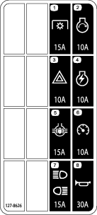
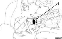
Servicing the Fuses
Jump-Starting the Machine
Warning
Jump-starting can be dangerous. To avoid personal injury or damage to electrical components in machine, observe the following warnings:
-
Never jump-start with a voltage source greater than 15 V DC; this damages the electrical system.
-
Never attempt to jump-start a discharged battery that is frozen. It could rupture or explode during jump-starting.
-
Observe all battery warnings while jump-starting your machine.
-
Be sure your machine is not touching the jump-start machine.
-
Connecting cables to the wrong post could result in personal injury and/or damage to the electrical system.
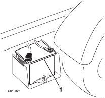
-
Squeeze the battery cover to release the tabs from the battery base and remove the battery cover from the battery base (Figure 51).
-
Connect a jumper cable between the positive posts of the 2 batteries (Figure 52).
Note: The positive post may be identified by a + sign on top of the battery cover.
-
Connect 1 end of the other jumper cable to the negative terminal of the battery in the other machine.
Note: The negative terminal has “NEG” on the battery cover.
Note: Do not connect the other end of the jumper cable to the negative post of the discharged battery. Connect the jumper cable to the engine or frame. Do not connect the jumper cable to the fuel system.
-
Start the engine in the machine providing the jump-start.
Note: Let it run for a few minutes, then start your engine.
-
Remove the negative jumper cable first from your engine, then the battery in the other machine.
-
Install the battery cover to the battery base.
Servicing the Battery
| Maintenance Service Interval | Maintenance Procedure |
|---|---|
| Every 50 hours |
|
Danger
Battery electrolyte contains sulfuric acid, which is fatal if consumed and causes severe burns.
-
Do not drink electrolyte or allow it to contact your skin, eyes or clothing. Wear safety glasses to shield your eyes and rubber gloves to protect your hands.
-
Fill the battery where clean water is always available for flushing the skin.
-
Always keep the battery clean and fully charged.
-
Always keep the battery clean and fully charged.
-
If the battery terminals are corroded, clean them with a solution of 4 parts water and 1 part baking soda.
-
Apply a light coating of grease to the battery terminals to prevent corrosion.
-
Maintain the battery electrolyte level.
-
Keep the top of the battery clean by washing it periodically with a brush dipped in ammonia or bicarbonate of soda solution. Flush the top surface with water after cleaning. Do not remove the fill cap while cleaning.
-
Ensure that the battery cables are kept tight on the terminals to provide good electrical contact.
-
Maintain the cell electrolyte level with distilled or demineralized water. Do not fill the cells above the bottom of the fill ring inside each cell.
-
If you store the machine in a location where temperatures are extremely high, the battery runs down more rapidly than if the machine is stored in a location where temperatures are cool.
Drive System Maintenance
Inspecting the Tires
| Maintenance Service Interval | Maintenance Procedure |
|---|---|
| Every 100 hours |
|
Front tires air pressure specification: 220 kPa (32 psi)
Rear tires air pressure specification: 124 kPa (18 psi)
Operating accidents, such as hitting curbs, can damage a tire or rim and also disrupt wheel alignment, so inspect the tire condition after an accident.
Important: Check the tire pressure frequently to ensure proper inflation. If the tires are not inflated to the correct pressure, the tires will wear prematurely and may cause 4-wheel drive to bind.
Figure 53 is an example of tire wear caused by under-inflation.
Figure 54 is an example of tire wear caused by over-inflation.
Checking the Torque of the Wheel Nuts
| Maintenance Service Interval | Maintenance Procedure |
|---|---|
| After the first 2 hours |
|
| After the first 10 hours |
|
| Every 200 hours |
|
Warning
Failure to maintain proper torque of the wheel nuts could result in failure or loss of a wheel and may result in personal injury.
Torque the front and rear wheel nuts to 109 to 122 N∙m (80 to 90 ft-lb) after 1 to 4 hours of operation and again after 10 hours of operation. Torque the wheel nuts every 200 hours thereafter.
Checking the Front Wheel Alignment
| Maintenance Service Interval | Maintenance Procedure |
|---|---|
| Every 400 hours |
|
-
Ensure that the tires are facing straight ahead.
-
Measure the center-to-center distance (at axle height) at the front and rear of the steering tires (Figure 55).
Note: The measurement must be within 0 ± 3 mm (0 ± 0.12 inch) at the front of the tire then at the rear of the tire. Rotate the tire 90° and check the measurement.
Important: Check the measurements at consistent locations on the tire. The machine should be on a flat surface with the tires facing straight ahead.
-
Adjust the center-to-center distance as follows:
-
Loosen the jam nut at the center of the tie rod (Figure 56).
-
Rotate the tie rod to move the front of the tire inward or outward to achieve the center to center distances from front to back.
-
Tighten the tie rod jam nut when the adjustment is correct.
-
Check to ensure that the tires turn an equal amount to the right and to the left.
Note: If the tires do not turn equally, refer to the Service Manual for the adjustment procedure.
-
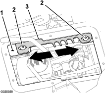
Maintaining the Transmission
Checking the Transmission-Fluid Level
| Maintenance Service Interval | Maintenance Procedure |
|---|---|
| After the first 50 hours |
|
| Every 400 hours |
|
Transmission-fluid type: Dexron VI
-
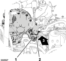
Locate the fill plug at the at the lower-inboard area at the back of the transmission (Figure 57).
-
Align a drain pan below the fill plug.
-
Rotate the plug counterclockwise and remove the plug from the fill port in the transmission (Figure 57).
Note: When the transmission fluid level is correct, the fluid should be level with the bottom of the threads in the fill port.
-
If the transmission-fluid level is low, add transmission fluid of the specified type into the transmission through the fill port until the fluid level is flush with the bottom of the threads in the port (Figure 57).
Note: Use a funnel with a flexible hose when filling the transmission.
-
Check the condition of the O-ring at the fill plug.
Note: Replace the O-ring if it is warn or damaged.
-
Install the fill plug into the transmission and tighten it by hand (Figure 57).
Changing the Transmission Fluid
Transmission-fluid type: Dexron VI
Transmission-fluid capacity: 700 ml (23.7 fl oz)
-
Park the machine to a level surface.
-
Locate the fill plug at the back inboard area of the transmission case and the locate the drain plug at the front outboard side of the transmission (Figure 58 and Figure 59).
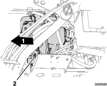
-
Remove the fill plug from the fill port by rotating the plug counterclockwise and removing it from the transmission (Figure 58).
-
Align a drain pan below the drain plug (Figure 59).
-
Remove the drain plug from the drain port by rotating the plug counterclockwise and removing it from the transmission (Figure 59).
Note: Allow the transmission fluid to drain completely.
-
Install the drain plug (Figure 59).
-
Add 700 ml (23.7 fl oz) of Dexron VI transmission fluid into the transmission through the fill port (Figure 58).
Note: Use a funnel with a flexible hose when filling the transmission.
Note: When the transmission fluid level is correct, the fluid should be level with the bottom of the threads in the fill port.
-
Install the fill plug (Figure 58).
Servicing the Reservoir of the Speed-Control Cylinder
| Maintenance Service Interval | Maintenance Procedure |
|---|---|
| Every 200 hours |
|
Reservoir-fluid type: DOT 3 brake fluid
-
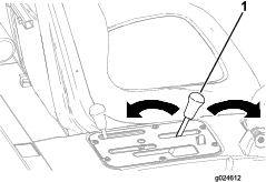
Remove the knobs from the hydraulic-lift lever and the speed-range lever (Figure 60).
-
Remove the 6 hex-washer screws (#10 x 3/4 inch) that secure the control-cover plate to the seat base, and remove the cover plate (Figure 60).
-
Move the speed-range lever to the TRANSPORT position; refer to Using the Speed-Range Control .
-
Check the fluid level in the reservoir for the speed-control cylinder (Figure 61).
Note: The normal fluid level is between the Min and Max marks on the side of the reservoir.
-
If the fluid level is low, perform the following:
-
Align the holes in the control-cover plate to the holes in the seat base (Figure 60).
-
Secure the plate to the base with the 6 hex-washer screws (Figure 60) that you removed in step 2.
-
Thread the knobs onto the rods for the hydraulic-lift lever and the speed-range lever (Figure 60).
Adjusting the Speed Control
Important: The minimum controlled speed for the machine is 4.0 kph (2.5 mph) at full engine speed. Controlling the machine speed slower that 4.0 kph (2.5 mph) results in excessive belt and clutch wear.
-
Drive the machine in speed range A (low range), B (mid-low range), C (mid-high range), or D (high range) in order to determine which speed range includes the maximum-ground speed that you want to set; refer to .
Note: Use the speedometer to determine the speed that the machine is traveling.
-
Remove the knobs from the hydraulic-lift lever and the speed-range lever (Figure 60).
-
Remove the 6 hex-washer screws (#10 x 3/4 inch) that secure the control-cover plate to the seat base, and remove the cover plate (Figure 60).
-
Move the speed-range lever to the (TRANSPORT) position (Figure 62).
-
Loosen the 2 hex-socket screws (5/16 x 3/4 inch) that secure the detent plate to the lever-support bracket (Figure 62).
-
Move the detent plate in one of the following directions:
-
Tighten the 2 hex-socket screws (5/16 x 3/4 inch) to 19.8 to 25.4 N∙m (14.6 to 18.7 ft-lb).
-
Drive the machine with the speed control set to speed range for which you are setting the maximum ground speed limit. If the maximum ground speed limit is too fast or too slow, repeat steps 1 through 8 until the correct maximum ground speed limit is attained.
-
Align the holes in the control-cover plate to the holes in the seat base (Figure 60).
-
Secure the plate to the base with the 6 hex-washer screws (Figure 60) that you removed in step 3.
-
Thread the knobs onto the rods for the hydraulic-lift lever and the speed-range lever (Figure 60).
Checking the Drive Belt
| Maintenance Service Interval | Maintenance Procedure |
|---|---|
| Every 400 hours |
|
-
Remove the 9 hex-washer bolts (1/4 x 1 inch) that secure the transmission cover to the mounting plate of the transmission (Figure 63).
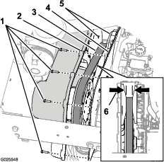
-
Move the cover forward until you can see the drive belt (Figure 63).
-
Check the tapered faces of the primary clutch for signs if damage (Figure 63).
Note: If the faces of the primary clutch are damaged, replace the primary clutch; contact your Authorized Service Dealer or Authorized Distributor.
-
Check the drive belt for missing or damaged cogs (Figure 63).
Note: If the cogs of the drive belt are missing or damaged, replace the drive belt.
-
Measure across the belt and record the belt width (Figure 63).
Note: If the width of the belt is 29.5 mm (1.16 inches) or less, replace the belt (Figure 63).
-
Align the holes in the transmission cover with the holes in the mounting plate (Figure 63).
-
Secure the cover to the mounting plate (Figure 63) with the 9 hex-washer bolts (1/4 x 1 inch) that you removed in step 1, and torque the bolts to 10.2 to 12.4 N∙m (90 to 110 in-lb).
Cleaning the Clutches
| Maintenance Service Interval | Maintenance Procedure |
|---|---|
| Every 400 hours |
|
-
Remove the 9 hex-washer bolts (1/4 x 1 inch) that secure the transmission cover to the mounting plate of the transmission (Figure 64).
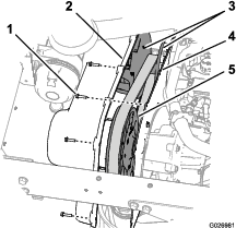
-
At the primary and secondary clutches, Remove dirt and mud buildup with water and dry immediately with compressed air to remove excess water and debris.
-
Remove any remaining debris using a fast-drying contact cleaner or brake cleaner.
Note: Note: Remove the debris in and around moving parts.
-
If debris or buildup exists around the belt or along the clutch shaft, use a fine abrasive pad or a similar product to remove it.
-
Align the holes in the transmission cover with the holes in the mounting plate (Figure 64).
-
Secure the cover to the mounting plate (Figure 64) with the 9 hex-washer bolts (1/4 x 1 inch) that you removed in step 1, and torque the bolts to 10.2 to 12.4 N∙m (90 to 110 in-lb).
Maintaining the Differential and Axles
Changing the Differential Oil
Oil type: 80W90 API GL-5
Oil capacity: 550 ml (18.6 fl oz)
-
Align a drain pan under the drain plug (Figure 65).
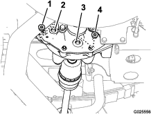
-
Remove the fill plug from the fill port and the drain plug from the drain port of the differential (Figure 65).
Note: Allow the differential to completely drain.
-
Check the condition of the O-rings on the plugs.
Note: Replace damaged or worn O-rings.
-
Install the drain plug into the drain port (Figure 65), and tight the plug to 14 to 19 N∙m (10 to 14 ft-lb).
Note: The drain plug is magnetic. It is normal to see small amounts of ferrous-metal particles around magnet—expect more particles around the magnet after the initial break-in.
-
Add 550 ml (18.6 fl oz) of the specified oil into the fill port of the differential (Figure 65).
Note: Use a funnel with a flexible hose to add oil to the differential.
-
Install the fill plug into the fill port (Figure 65), and tighten the plug to 14 to 19 N∙m (10 to 14 ft-lb).
Checking the Constant-Velocity Boots
| Maintenance Service Interval | Maintenance Procedure |
|---|---|
| Every 100 hours |
|
-
Jack up the back end of the machine and support it with jack stands; refer to Raising the Machine.
-
Check the CV (constant velocity) boots at the rear axles for damage and leaking lubricant (Figure 66).
Note: Replace any damaged or leaking CV boot before operating the machine.
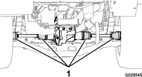
-
Remove the jack stands and lower the machine to the ground.
Cooling System Maintenance
Cooling System Safety
-
Swallowing engine coolant can cause poisoning; keep out of reach from children and pets.
-
Discharge of hot, pressurized coolant or touching a hot radiator and surrounding parts can cause severe burns.
-
Always allow the engine to cool at least 15 minutes before removing the radiator cap.
-
Use a rag when opening the radiator cap, and open the cap slowly to allow steam to escape.
-
-
Do not operate the machine without the covers in place.
-
Keep your fingers, hands and clothing clear of rotating fan and drive belt.
-
Shut off the engine and remove the key before performing maintenance.
Checking the Engine-Coolant Level
| Maintenance Service Interval | Maintenance Procedure |
|---|---|
| Before each use or daily |
|
Coolant type: a 50/50 solution of water and permanent ethylene-glycol antifreeze
Caution
If the engine has been running, the pressurized, hot coolant can escape and cause burns.
-
Do not open the radiator cap.
-
Allow the engine to cool for at least 15 minutes or until the radiator cap is cool enough to touch without burning your hand.
-
Use a rag when opening the reserve-tank cap, and open the cap slowly to allow steam to escape.
-
Do not check the coolant level at the radiator; check the coolant level at the reserve tank only.
-
Park the machine on a level surface.
-
Engage the parking brake.
-
Shut off the engine and remove the key.
-
Check the coolant level at the reserve tank (Figure 67).
Note: The coolant should be up to the bottom of the filler neck.
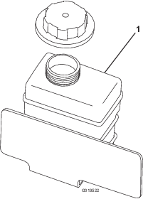
-
If coolant is low, remove the reserve- tank cap and add a 50/50 mixture of water and permanent ethylene-glycol antifreeze.
Note: Do not overfill.
-
Install the reserve-tank cap.
Removing Debris from the Cooling System
| Maintenance Service Interval | Maintenance Procedure |
|---|---|
| Before each use or daily |
|
-
Park the machine on a level surface.
-
Engage the parking brake.
-
Shut off the engine and remove the key.
-
Clean the engine area thoroughly of all debris.
-
Unlatch and remove the radiator screen from the front of the radiator (Figure 68).
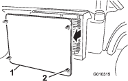
-
If equipped, rotate the latches and pivot the oil cooler away from the radiator (Figure 69).
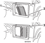
-
Clean the radiator, oil cooler, and screen with compressed air.
Note: Blow debris away from the radiator.
-
Install the cooler and screen to the radiator.
Changing the Engine Coolant
| Maintenance Service Interval | Maintenance Procedure |
|---|---|
| Every 1,000 hours |
|
Cooling-system capacity: 3.7 L (4 US qt)
Coolant type: a 50/50 solution of water and permanent ethylene-glycol antifreeze
-
Park the machine on a level surface.
-
Raise the bed and install the bed safety support on the extended lift cylinder to secure the bed.
Caution
If the engine has been running, the cooling system pressurizes with hot coolant that can escape and cause burns.
-
Do not open the radiator cap when the engine is running.
-
Allow the engine to cool for at least 15 minutes or until the radiator cap is cool enough to touch without burning your hand.
-
Use a rag to open the radiator cap. Open the cap slowly to allow the steam to escape.
-
-
Remove the radiator cap (Figure 70).
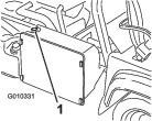
-
Remove the reserve-tank cap (Figure 70).
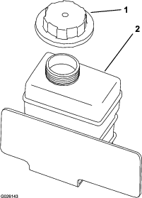
-
Disconnect the lower radiator hose and allow the coolant to flow into a drain pan.
Note: When the coolant stops flowing, connect the lower radiator hose.
-
Slowly fill the radiator with a 50/50 mixture of water and permanent ethylene-glycol antifreeze
-
Top off the radiator and install the cap (Figure 70).
-
Slowly fill the coolant-reserve tank until level reaches the bottom of the filler neck (Figure 71).
-
Install the reserve-tank cap (Figure 71).
-
Start the engine and operate it until it is warm.
-
Shut off the engine, check the coolant level, and replenish the coolant, if necessary.
Brake Maintenance
Checking the Brake-Fluid Level
| Maintenance Service Interval | Maintenance Procedure |
|---|---|
| Before each use or daily |
|
| Every 1,000 hours |
|
Brake-fluid type: DOT 3 brake fluid
Note: The brake-fluid reservoir ships from the factory filled with DOT 3 brake fluid.
-
Park the machine on a level surface.
-
Engage the parking brake.
-
Shut off the engine and remove the key.
-
Remove the hood.
-
Check the fluid level in the brake-fluid reservoir (Figure 72 and Figure 73).
Note: The fluid level should be up to the Full line on the reservoir.
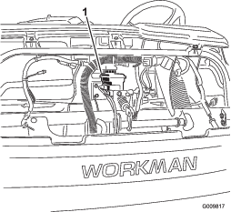
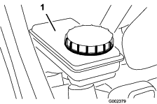
-
If the fluid level is low, perform the following:
-
Install the hood.
Adjusting the Parking Brake
| Maintenance Service Interval | Maintenance Procedure |
|---|---|
| After the first 10 hours |
|
| Every 200 hours |
|
-
Remove the rubber grip from the parking-brake lever (Figure 74).
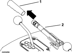
-
Loosen the set screw securing the knob to the parking-brake lever (Figure 75).
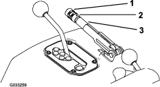
-
Rotate the knob (Figure 75) until a force of 20 to 22 kg (45 to 50 lb) is required to actuate the lever.
-
Tighten the set screw when finished (Figure 75).
Note: If you can no longer make a parking-brake adjustment by adjusting the parking-brake lever, loosen the handle to the middle of the adjustment and adjust the cable at the rear, then repeat step 3.
-
Install the rubber grip onto the parking-brake lever (Figure 74).
Adjusting the Brake Pedal
| Maintenance Service Interval | Maintenance Procedure |
|---|---|
| Every 200 hours |
|
-
Remove the hood.
-
Remove the cotter pin and clevis pin securing the master cylinder yoke to the brake-pedal pivot (Figure 76).
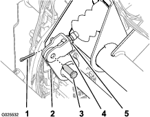
-
Lift up on the brake pedal (Figure 77) until it contacts the frame.
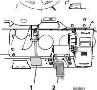
-
Loosen the jam nuts securing the yoke to the master cylinder shaft (Figure 76).
-
Adjust the yoke until its holes align with the hole in the brake-pedal pivot (Figure 76).
-
Secure the yoke to the pedal pivot with the clevis pin and cotter pin (Figure 76).
-
Tighten the jam nut securing the yoke to the master cylinder shaft (Figure 76).
Note: The brake master cylinder must relieve the pressure from the service brake when it is properly adjusted.
-
Install the hood.
Controls System Maintenance
Converting the Speedometer
You can convert the speedometer from mph to kpm or kph to mph.
-
Position the machine on a level surface, shut off the engine, engage the parking brake, and remove the key.
-
Remove the hood.
-
Locate the 2 loose wires next to the meter (Figure 78).
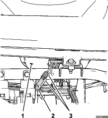
-
Remove the connector plug from the harness wire and connect the wires together (Figure 78).
Note: The meter switches from mph to kph. Retain the plug in order to convert the speedometer to mph.
-
Install the hood.
Hydraulic System Maintenance
Hydraulic System Safety
-
Seek immediate medical attention if fluid is injected into skin. Injected fluid must be surgically removed within a few hours by a doctor.
-
Before disconnecting or performing any work on the hydraulic system, relieve all pressure in the system by shutting off the engine, cycling the dump valve from raise to lower, and/or lowering the cargo bed and attachments. Place the remote hydraulics lever in the float position. Do not work under a raised bed without the proper bed safety support in place.
-
Ensure that all hydraulic-fluid hoses and lines are in good condition and that all hydraulic connections and fittings are tight before applying pressure to the hydraulic system.
-
Keep your hands and body away from pinhole leaks or nozzles that eject high-pressure hydraulic fluid.
-
Use cardboard or paper to find hydraulic leaks.
Checking the Hydraulic-Fluid Level
| Maintenance Service Interval | Maintenance Procedure |
|---|---|
| Before each use or daily |
|
Hydraulic-fluid type: Mobil M15
Hydraulic-fluid capacity: (Non-TC model): 7.5 L (2 US gallons)
Hydraulic-fluid capacity: (Non-TC model with the High-Flow-Hydraulic Kit (optional kit) or TC Model): 15.1 L (4 US gallons)
Warning
Hydraulic fluid escaping under pressure can penetrate skin and cause injury.
-
Ensure that all hydraulic-fluid hoses and lines are in good condition and all hydraulic connections and fittings are tight before applying pressure to the hydraulic system.
-
Keep your body and hands away from pinhole leaks or nozzles that eject high-pressure hydraulic fluid.
-
Use cardboard or paper to find hydraulic leaks.
-
Safely relieve all pressure in the hydraulic system before performing any work on the hydraulic system.
-
Seek immediate medical attention if fluid is injected into your skin.
-
Park the machine on a level surface.
-
Engage the parking brake.
-
Shut off the engine and remove the key.
-
Clean the area around the filler neck and the cap of the hydraulic reservoir (Figure 79 and Figure 80).
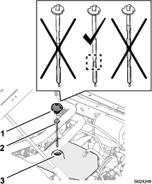
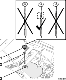
-
Remove the cap and dipstick from the filler neck of the reservoir and wipe the dipstick clean with a rag (Figure 79 and Figure 80).
-
Insert the dipstick into the filler neck; then remove it and check the fluid level (Figure 79 and Figure 80).
-
Non-TC model: The hydraulic-fluid level should be between the lower indented area on the dipstick.
-
Non-TC model with the High-Flow-Hydraulic Kit (option) or TC model: The hydraulic-fluid level should be between the upper indented area on the dipstick.
-
-
If the level is low, add the specified hydraulic fluid into the reservoir to raise the level to the middle of the indented area on the dipstick (Figure 79 and Figure 80).
-
Install the dipstick and cap to the filler neck of the reservoir (Figure 79 and Figure 80).
Replacing the Hydraulic Filter
| Maintenance Service Interval | Maintenance Procedure |
|---|---|
| After the first 10 hours |
|
| Every 800 hours |
|
Important: Use of any other filter may void the warranty on some components.
-
Park the machine on a level surface, shut off the engine, engage the parking brake, and remove the key.
-
Clean the area around filter-mounting area (Figure 81).
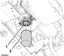
-
Place a drain pan under the filter (Figure 81).
-
Remove the filter by rotating it counterclockwise (Figure 81).
-
Clean the filter-seating surface of the filter adapter (Figure 81).
-
Lubricate the gasket on the new filter with the specified Mobil M15 hydraulic fluid.
-
Thread the filter onto the filter adapter until the gasket of the filter contacts the seating surface of the adapter (Figure 81), and then tighten the filter an additional 1/2 turn (Figure 81).
-
Start the engine and let it run for about 2 minutes to purge air from the system.
-
Shut off the engine and check the hydraulic-fluid level in the hydraulic tank and the filter area for leaks.
Changing the Hydraulic Fluid
| Maintenance Service Interval | Maintenance Procedure |
|---|---|
| Every 800 hours |
|
Hydraulic-fluid type: Mobil M15
Hydraulic-fluid capacity: (Non-TC model): 7.5 L (2 US gallons)
Hydraulic-fluid capacity: (Non-TC model with the High Flow Hydraulic Kit (option) or TC model): 15.1 L (4 US gallons)
-
Park the machine on a level surface, shut off the engine, engage the parking brake, and remove the key.
-
Raise the cargo bed.
-
Remove the cap and dipstick from the filler neck of the hydraulic tank (Figure 82).
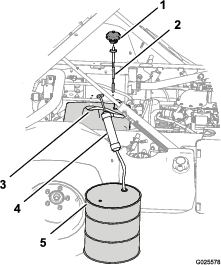
-
Route the intake hose of the siphoning equipment through the filler neck of the hydraulic tank and to the bottom of the tank (Figure 82).
-
Direct the discharge hose of the siphoning equipment into a collection container (Figure 82) with a 11.4 L (3 US gallon) capacity—Non-TC model or 18.9 L (5 US gallon) capacity—Non-TC model with the High Flow Hydraulic Kit (option) or TC model.
-
Siphon the hydraulic fluid from the hydraulic tank.
-
Remove the siphoning equipment from the hydraulic tank (Figure 82).
-
Add 7.5 L (2 US gallons)—Non-TC model or 15.1 L (4 US gallons)—Non-TC model with the High Flow Hydraulic Kit (option) or TC model of the specified hydraulic fluid into the hydraulic tank (Figure 82).
Important: Use only the hydraulic fluids specified. Other fluids could cause system damage.
-
Install the dipstick and cap to the filler neck of the hydraulic tank (Figure 82).
-
Start the engine and operate the machine to fill the hydraulic system.
-
Check the hydraulic-fluid level and replenish it, if required.
Raising the Cargo Bed in an Emergency
The cargo bed can be raised in an emergency without starting the engine by cranking starter or by jumping the hydraulic system.
Raising the Cargo Bed using the Starter
Crank the starter while holding the lift lever in the Raise position. Run the starter for 10 seconds, then wait 60 seconds before engaging the starter again. If the engine does not crank, you must remove the load and bed (attachment) to service the engine or transaxle.
Raising the Cargo Bed by Jumping the Hydraulic System
Caution
A raised bed full of material without the proper safety support rod may lower unexpectedly. Working under an unsupported raised bed may cause injury to you or others.
-
Before servicing or making adjustments to the machine, park the machine on a level surface, engage the parking brake, shut off the engine, and remove the key.
-
Remove any load material from the bed or other attachment and insert the safety support on a fully extended cylinder rod before working under a raised bed.
You will need 2 hydraulic hoses, each with a male and female quick coupler, that fit the machine couplers, to perform this operation.
-
Back another machine up to the rear of the disabled machine.
Important: The machine hydraulic system uses Dexron III ATF. To avoid system contamination, make sure that the machine used to jump the hydraulic system uses an equivalent fluid.
-
On both machine, disconnect the 2 quick-coupler hoses from the hoses secured to the coupler bracket (Figure 83).
-
On the disabled machine, connect the 2 jumper hoses to the hoses that were disconnected (Figure 84).
-
Cap the unused fittings.
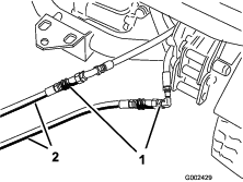
-
On the other machine, connect the 2 hoses to the coupler still in the coupler bracket (connect the top hose to the top coupler and the bottom hose to the bottom coupler) (Figure 85).
-
Cap the unused fittings.
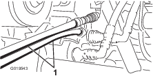
-
Keep all bystanders away from the machines.
-
Start the second machine and move the lift lever to the raise position, which raises the disabled cargo bed.
-
Move the hydraulic-lift lever to the NEUTRAL position, and engage the lift-lever lock.
-
Install the bed support onto the extended lift cylinder; refer to Using the Bed Support.
Note: With both the machine turned off, move the lift lever back and forth to remove the system pressure and ease the disconnection of the quick couplers.
-
After completing the operation, remove the jumper hoses and connect the hydraulic hoses to both machines.
Important: Check the hydraulic fluid levels, in both machines, before resuming operation.
Cleaning
Washing the Machine
The machine should be washed as needed. Use water alone or with a mild detergent. A rag may be used when washing the machine.
Important: Do not use power washing equipment to wash the machine. Power washing equipment may damage the electrical system, loosen important decals, or wash away necessary grease at friction points. Avoid excessive use of water near the control panel, engine, and battery.
Important: Do not wash the machine with the engine running. Washing the machine with the engine running may result in internal engine damage.
Storage
Storage Safety
-
Let the engine cool before storing the machine.
-
Do not store the machine or fuel near flames or drain the fuel indoors.
Storing the Machine
| Maintenance Service Interval | Maintenance Procedure |
|---|---|
| Every 200 hours |
|
| Every 400 hours |
|
| Yearly |
|
-
Position the machine on a level surface, engage the parking brake, shut off the engine, and remove the key from the key switch.
-
Clean dirt and grime from the entire machine, including the outside of the engine cylinder head fins and blower housing.
Important: You can wash the machine with mild detergent and water. Do not use high-pressure water to wash the machine. Pressure washing the machine may damage the electrical system or wash away necessary grease at friction points. Avoid excessive use of water, especially near the control panel, lights, engine, and battery.
-
Inspect the brakes; refer to Checking the Brake-Fluid Level.
-
Service the air cleaner; refer to Servicing the Air Filter.
-
Grease the machine; refer to Greasing the Bearings and the Bushings.
-
Change the engine oil and filter; refer to Changing the Engine Oil and Filter.
-
Check the tire pressure; refer to Checking the Tire Pressure.
-
For storage over 30 days, prepare the fuel system as follows:
-
Add a petroleum based stabilizer/conditioner to the fuel in the tank.
Follow mixing instructions from the stabilizer manufacturer. Do not use an alcohol-based stabilizer (ethanol or methanol).
Note: A fuel stabilizer/conditioner is most effective when mixed with fresh gasoline and the stabilizer/conditioner is used at all times.
-
Run the engine to distribute conditioned fuel through the fuel system for 5 minutes.
-
Shut off the engine, allow it to cool, and drain the fuel tank.
-
Start the engine and run it until it stops.
-
Start and run the engine again until it does not start again.
-
Dispose of drained fuel properly. Recycle as per local codes.
Important: Do not store stabilizer/conditioned gasoline for over 90 days.
-
-
Remove the spark plugs and check their condition; refer to Servicing the Spark Plugs.
-
With the spark plugs removed from the engine, pour 2 tablespoons of engine oil into the spark-plug hole.
-
Use the starter to crank the engine and distribute the oil inside the cylinder.
-
Install the spark plugs and tighten each one to the recommended torque; refer to Servicing the Spark Plugs.
Note: Do not install the spark-plug wires on the spark plugs.
-
Check the anti freeze protection and add a 50/50 solution of water and anti freeze as needed for expected minimum temperature in your area.
-
Remove the battery from the chassis, and charge it fully; refer to Servicing the Battery.
Note: Do not connect the battery cables to the battery posts during storage.
Important: The battery must be fully charged to prevent it from freezing and being damaged at temperatures below 0°C (32°F). A fully charged battery maintains its charge for about 50 days at temperatures lower than 4°C (40°F). If the temperatures will be above 4°C (40°F), check the water level in the battery and charge it every 30 days.
-
Check and tighten all the bolts, nuts, and screws. Repair or replace any part that is damaged.
-
Paint all the scratched or bare metal surfaces.
Note: Paint is available from your Authorized Service Distributor.
-
Store the machine in a clean, dry garage or storage area.
-
Remove the key from the key switch and put it in a safe place that is out of the reach of children.
-
Cover the machine to protect it and keep it clean.
Troubleshooting
| Problem | Possible Cause | Corrective Action |
|---|---|---|
| The quick couplers are difficult to connector disconnect. |
|
|
| The power steering moves hard. |
|
|
| The hydraulic fitting leaks. |
|
|
| An attachment does not function. |
|
|
| A squealing noise is heard. |
|
|
| The engine does not start. |
|
|
| The transmission is hard to shift. |
|
|
| The clutch engagement is abrupt. |
|
|