


Maintenance
Recommended Maintenance Schedule(s)
| Maintenance Service Interval | Maintenance Procedure |
|---|---|
| After the first 50 operating hours |
|
| Before each use or daily |
|
| Every 50 hours |
|
| Every 500 hours |
|
| Before storage |
|
| Yearly |
|
Maintenance Safety
-
Before servicing or making adjustments to the machine, stop the machine, shut off the engine, engage the parking brake, remove the key, and wait for all moving parts to stop.
-
Perform only those maintenance instructions described in this manual. If major repairs are ever needed or assistance is desired, contact an authorized Toro distributor.
-
Ensure that the machine is in safe operating condition by keeping nuts, bolts, and screws tight.
-
If possible, do not perform maintenance while the engine is running. Keep away from moving parts.
-
Do not check or adjust the chain tension when the tractor engine is running.
-
Carefully release pressure from components with stored energy.
-
Support the machine with blocks or storage stands when working beneath it. Never rely on the hydraulic system to support the machine.
-
Check the tine mounting bolts daily to be sure that they are tightened to specification.
-
Ensure that all guards are installed and the hood is secured shut after maintaining or adjusting the machine.
Lifting the Machine
Caution
If the machine is not properly supported, the machine may move or fall, which may result in personal injury.
When changing attachments or performing other service, use correct blocks, hoists, or jacks. Ensure that the machine is parked on a solid level surface such as a concrete floor. Prior to raising the machine, remove any attachments that may interfere with the safe and proper raising of the machine. Always chock or block the wheels of the tow vehicle. Use storage stands or blocks to support the raised machine.
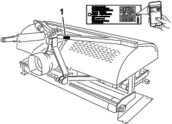
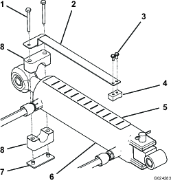
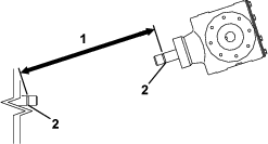
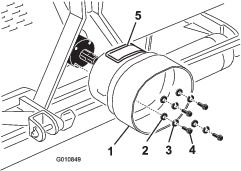
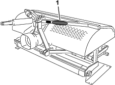
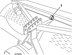
Note: You can use a hoist to lift the aerator. Use the coring head eyelet as a hoist attachment point (Figure 44). Ensure that the hoist has enough lift capacity. Refer to Specifications.
Greasing the Bearings
The main working bearings of the aerator are sealed and require no maintenance or lubrication. This reduces the maintenance required and eliminates the risk of grease or oil being dropped onto the turf.
There are grease fittings that must be lubricated with an SAE multipurpose, high-temperature grease with high-pressure (EP) performance or SAE multipurpose lithium grease.
The lubrication points are as follows:
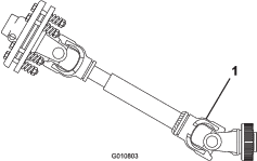
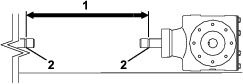
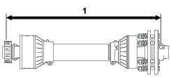
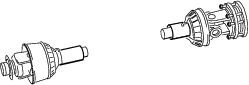
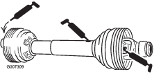
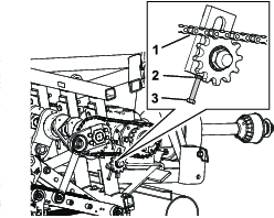
PTO shaft (3) (Figure 45)
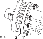
Roller bearings (2 or 4, depending on model) (Figure 46)
O-ring chain — Do not lubricate the chain.
Important: Bearings rarely fail from defects in materials or workmanship. The most common reason for failure is moisture and contamination working its way past the protective seals. Bearings that are greased rely upon regular maintenance to purge harmful debris from the bearing area. Sealed bearings rely on an initial fill of special grease and a robust integral seal to keep contaminants and moisture out of the rolling elements.
The sealed bearings require no lubrication or short term maintenance. This minimizes routine service required and reduces the potential of turf damage due to grease contamination. These sealed bearing packages will provide good performance and life under normal use, but periodic inspections of bearing condition and seal integrity should be conducted to avoid downtime. Inspect these bearings seasonally and replace them if they are damaged or worn. Bearings should operate smoothly with no detrimental characteristics such as high heat, noise, looseness or rust weeping.
Due to the operating conditions that these bearing/seal packages are subject to (i.e., sand, turf chemicals, water, impacts, etc.) they are considered normal wear items. Bearings that fail due to other than defects in materials or workmanship are typically not covered under warranty.
Note: Bearing life can be negatively affected by improper wash down procedures. Do not use high-pressure or high volume spray directly at the bearings.It is common for new bearings to purge some grease out the seals on a new unit. This purged grease turns black in color due to collection of debris and not due to excessive heat. Wipe this excess grease from the seals after the initial 8 hours. There may always appear to be a wet area around the seal lip. This is not detrimental to bearing life, but keeps the seal lip lubricated.
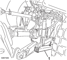
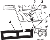
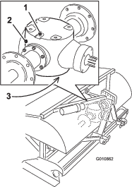
Checking the Gearbox Oil
The gearbox is filled with 80W–90 gear oil or equivalent. Allow the gearbox to cool before checking the oil level.
-
Clean debris from the fill plug and check plug to avoid contamination.
-
Remove the check plug from the gearbox (Figure 47).
Note: If the gearbox has 2 check plugs, use the lower plug.
-
Ensure that oil is up to the bottom of the check plug hole in the gearbox (Figure 47).
-
If the oil level is low, remove the vent/fill plug from top of the gearbox and replenish the oil as required.
-
Install the plugs.
Changing the Gearbox Oil
The gearbox is filled with 80W-90 gear oil or equivalent.
-
Clean debris from vent/fill plug and drain plug to avoid contamination (Figure 47).
-
Remove the vent/fill plug to relieve air draw.
-
Position a drain pan under the drain plug and remove the plug.
Note: The high viscosity of cool oil will extend the drain time (approximately 30 minutes).
-
After the oil is completely drained, reinstall the drain plug.
-
Fill the gearbox with high quality 80W-90 gear oil. Use the following chart to determine the gearbox oil capacity.
Model Gear Case Capacity SR54 1.9 L (2 US qt) SR54-S 1.9 L (2 US qt) SR70 1.9 L (2 US qt) SR70-S 1.9 L (2 US qt) SR72 3.8 L (4 US qt) -
Install the vent/fill plug.
-
Check the oil level and replenish as required.
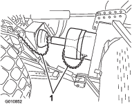
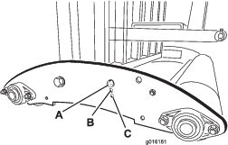
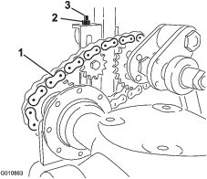
Inspecting/Adjusting the Drive Chain
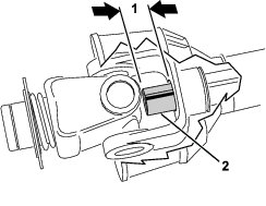
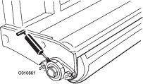
Check the drive chain for damage and correct adjustment. The chain should have approximately 13 mm (1/2 inch) of overall deflection (6 mm [1/4 inch] in each direction).
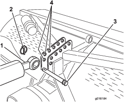
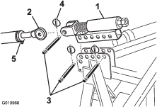
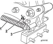
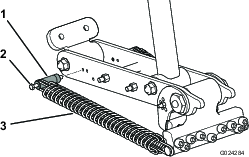
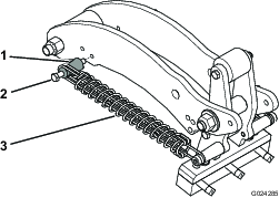
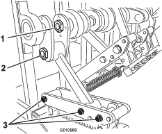
Chain tension can be adjusted by slightly loosening the main jam nut and tightening the jam rod to desired position (Figure 48 or Figure 49). Do not adjust the chain tension when the chain is hot or warm.
Important: Do not overtighten the chains; excess tightening of chains can cause gearbox/sprocket damage.
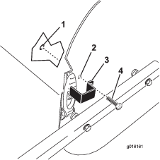
Adjusting the PTO Clutch
Warning
Friction clutches may become hot during use.
Do not touch. To avoid the risk of fire, keep the area around the clutch free of flammable material and avoid prolonged slipping of the clutch.
-
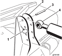
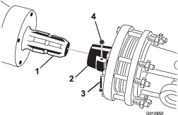
At the end of the season, back off each of the clutch nuts 2 turns (Figure 50).
-
At the start of the new season, start the PTO and allow the clutch to slip for a few seconds before stopping the PTO. Turn back the nuts an additional 2 turns.
Note: Do not allow the clutch to slip for an extended amount of time.
-
If the clutch continues to slip after turning back the nuts, tighten each nut an additional 1/4 turn until the slipping ceases. Do not overtighten the nuts, as shaft damage may occur.
Fastener Torque Specifications
| Models SR54, SR54-S, SR70, and SR70-S | SR72 | |
| Crank shaft nut | 1288 N∙m (950 ft-lb) | 1627 N∙m (1200 ft-lb) |
| Crank pin nut | 1288 N∙m (950 ft-lb) | 1288 N∙m (950 ft-lb) |
| Hinge bolt | 359 N∙m (265 ft-lb) | 407 N∙m (300 ft-lb) |
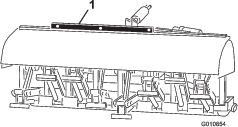
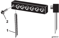
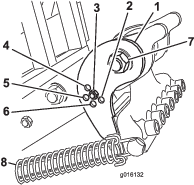
Checking the Springs
Check the springs for crossed or broken wires (Figure 52). Crossed or broken spring wires will cause an erratic hole pattern in the turf.
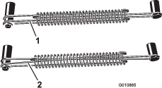
Note: Replacement wires are included with the aerator. The wires are considered a consumable item.
Adjusting the Hole Spacing
The forward hole spacing is determined by the tractor gear ratio (or the hydrostatic traction pedal). Changing the engine speed does not change the forward hole spacing.
The lateral hole spacing is determined by the number of tines in the tine heads.
Removing the Aerator from the Tractor
-
Stop the aerator on a level surface, not on a slope.
-
Disengage the PTO and engage the parking brake.
-
Raise the aerator roller(s) 7.5 to 15 cm (3 to 6 inches) off the ground. Place support blocks under the roller(s).
-
Shut off the engine and remove the key.
-
Before leaving the operator's seat on the tractor, shut off the engine, remove the key, and wait for all moving parts to stop.
-
Remove the tines.
-
Install the storage stand.
-
Slowly lower the aerator until the storage stands contact the ground.
-
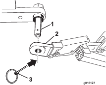
Remove the pin securing the top link to the aerator bracket. Retain the pin with the aerator.
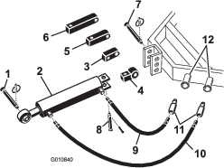
Also, on models with a hydraulic top link, disconnect the hydraulic hoses and the connecting link from the tractor. Cap the hydraulic hoses. Store these components with the aerator.
-
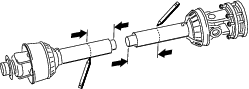
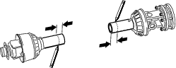
Disconnect the safety shield chains from PTO shaft.
-
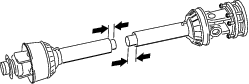
Pull back on the lock collar to disconnect the power shaft from the tractor PTO shaft.
-
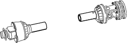
Slide the PTO shaft back and remove it from the tractor.
-
Connect the PTO safety chain to the aerator to prevent the PTO shaft from contacting the ground.
-
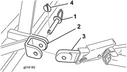
Remove the pins securing the lower link arms to the aerator brackets. Retain the pins with the aerator.
Troubleshooting
| Problem | Solution |
| Springs are breaking or not pulling back the head to normal position. | Slow the PTO speed of the tractor. The longer and heavier the tines, the greater the centrifugal force on the head. Check for crossed or broken spring wires. |
| Holes are elongated or picking. | Adjust the angle of the tine or change the tractor ground speed. Make sure that the aerator can be lowered at least 5 cm (2 inches) below flat ground level to allow for undulation. |
| Tines are hitting the ground with an erratic pattern. | Check for crossed or broken spring wires. Slow the PTO speed of the tractor. |
| PTO clutch slips excessively. | Adjust the tines to a shallower depth. Review the clutch adjustment procedure. Replace PTO clutches. |
| Turf is pulling up with coring tines. | Shallow-rooted turf may require solid tines the first time. |
| The soil is too hard for full penetration. | Aerate at a depth that the machine can achieve, water overnight, and then increase the depth. Repeat if necessary until soil can be aerated at the desired depth. |
| Coring tines are breaking. | You are trying to get too much depth for the soil condition. See above and aerate to a shallower depth. |
| The tines do not stay in the head. | Tighten the tine holder bolts; do not use jam nuts or an impact wrench. If the bolt does not hold the tine, replace it. |
| Tines pull the soil up when the machine is raised. | Raise the machine part of the way out of the soil before disengaging the PTO. |
| The machine does not turn. | Ensure that the PTO, driveshaft, and drive chains are working properly. |
| The tractor has difficulty lifting the aerator. | Move the tractor lift arms 7.5 to 10 cm (3 to 4 inches) closer to the aerator. Ensure that the tractor has the capacity to lift the aerator. |
| The hydraulic top link cylinder is spongy. (It “gives and moves in and out a short span when force is applied. | Air is in the cylinder or lines and must be bled out. |
| The machine is noisy or knocking. | The crank pin nut has vibrated loose. The chains are too loose.The bolts on the bottom of the frame at the rear of the main arm have vibrated loose.Check the oil level in the gearbox. |
| The hydraulic top link cylinder can not be fully retracted (PTO shaft jams). | The PTO shaft is too long for your tractor and should be cut to the correct length. |
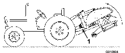
| The tractor is difficult to steer when in transport. | Add weight to the front of the tractor.Check the tire pressure and adjust it as required. |
| The camber bracket is damaged. | Do not store the aerator on the ground with tines installed.Do not run the coring head at high speed for an extended time when the tines are out of the ground. |