Warning
CALIFORNIA
Proposition 65 Warning
This product contains a chemical or chemicals known to the State of California to cause cancer, birth defects, or reproductive harm.
Setup
Preparing the Machine
-
Park the machine on a level surface.
-
Engage the parking brake.
-
Shut off the engine and remove the key.
-
Allow the engine to cool.
-
Disconnect the battery; refer to your machine Operator’s Manual.
Preparing to Install the Leak Detector Tank
Parts needed for this procedure:
| Wire harness | 1 |
| Cable tie | 8 |
| Indicator light | 1 |
| Audio alarm | 1 |
| Spout | 1 |
-
Remove the hex-head screws that secure the console arm cover and remove the cover.
Note: Save the screws for securing the console arm cover later.
-
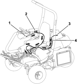
Route the wire harness by positioning the light indicator and alarm leads in the console arm, following the main wire harness under the seat to the other side of the machine, and then behind the seat along the left-hand rail, so that the oil level sensor and solenoid valve leads are near the main hydraulic tank (diesel model only).
Refer to Figure 1 for an overview of the wire-harness position and the connector locations.
-
Use cable ties to secure the wire harness to the main wire harness and frame members away from any hot or moving parts (for diesel model only).
-
Remove the plug on the console arm panel and insert the indicator light.
-
Connect the indicator-light connector to the main wire harness (gasoline model only) or to the kit wire harness (diesel model only).
-
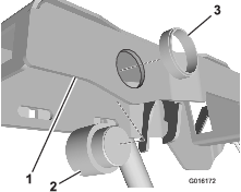
Install the audio alarm into the console arm frame (Figure 2).
-
Connect the audio alarm to the main wire harness (gasoline model only) or to the kit wire harness (diesel model only).
-
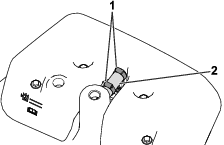
If your machine is equipped with an overflow hose, loosen the worm-drive clamps and remove the overflow hose (Figure 3).
Note: Discard the overflow hose and worm-drive clamps.
-
Remove the 4 bolts, washers, spacers, and rubber washers that secure the tank cover to the main hydraulic tank.
Note: Save the bolts, spacers, and washers for securing the leak detector tank to the main hydraulic tank later.
-
Remove the tank cover from the main hydraulic tank.
-
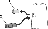
Remove the plug from the hydraulic tank (if equipped); refer to Figure 4.
-
Insert the spout into the rubber grommet (Figure 4).
Installing the Leak Detector Tank
Parts needed for this procedure:
| Leak detector tank | 1 |
| Oil level sensor | 1 |
| O-ring | 1 |
| Valve hose | 1 |
| Tank valve hose | 1 |
| Hex-head bolt (1/4 x 2 inches) | 2 |
| Shield bracket | 1 |
| Hose clamp | 4 |
| Solenoid valve assembly | 1 |
| Straight fitting | 1 |
| 90° hydraulic fitting | 2 |
| 90° hydraulic fitting (beaded) | 1 |
| Delay timer (diesel model only) | 1 |
| Screw (5/8 inch) | 1 |
| Locknut | 1 |
| Oil level cover (diesel model only) | 1 |
| Oil level cover (gasoline model only) | 1 |
| Overflow hose | 1 |
| Worm-drive clamp | 2 |
-
Find the appropriate oil-level cover for your machine from loose parts.
There are 2 different oil-level covers in the kit, 1 for gasoline machines and the other for diesel machines. The cover for the diesel machine is longer than the cover for the gasoline machine and may have a “D etched in it.
-
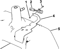
Use the screw (5/8 inch) and locknut to install the delay timer on the oil-level cover (diesel model only); refer to Figure 5.
-
Set the oil-level cover in place, but do not secure it to the main hydraulic tank yet (Figure 5).
-
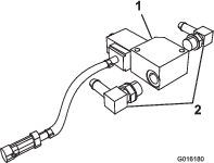
Install 2 hydraulic fittings (90°) onto the front and back of the solenoid valve (Figure 6).
Note: Position the 90° hydraulic fittings so that the hoses that attach to them are parallel to the ground when installed.
-
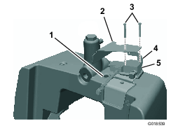
Install the 90° beaded hydraulic fitting to the main hydraulic tank (Figure 7).
-
Install 1 end of the tank valve hose to the 90° hydraulic fitting connected to the front of the solenoid valve with a worm-drive clamp.
-
Slip a worm-drive clamp over the other end of the tank valve hose.
-
Connect the free end of the tank valve hose onto the 90° beaded hydraulic fitting on the main hydraulic tank as you lower the solenoid-valve assembly onto the oil-level cover.
-
Install the oil-level cover and solenoid-valve assembly to the main hydraulic tank with 2 hex-head bolts and the shield bracket (Figure 5).
Note: Before installing the bolts, coat the bottom 2 or 3 threads with anti-seize compound.
-
Torque the bolts to 3 to 7 N∙m (30 to 60 in-lb).
-
Secure the tank-valve-hose end onto the 90° beaded hydraulic fitting with the worm-drive clamp.
-
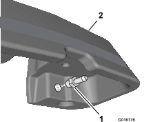
Install the straight hydraulic fitting into the opening on the underside of the leak detector tank (Figure 8).
-
Secure 1 end of the valve hose to the 90° hydraulic fitting connected to the back of the solenoid valve with a worm-drive clamp.
-
Slip a worm-drive clamp over the free end of the valve hose, and secure the end of the valve hose to the straight hydraulic fitting on the leak detector tank.
-
Use 2 worm-drive clamps to secure the overflow hose to the leak detector tank and the hydraulic tank (Figure 3).
-
Connect the delay time connector to the connector on the wire harness (diesel model only).
-
Connect the solenoid valve connector to the connector marked “Leak Detector Solenoid on the wire harness.
-
Remove the plug from the main hydraulic tank (Figure 9).
-
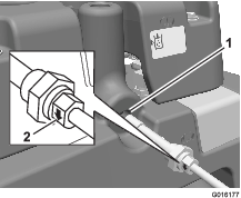
Slide the O-ring onto the hydraulic-oil-level sensor and install the sensor into the hydraulic tank (Figure 9).
Important: Ensure that the indicator arrow on each side of the nut that secures the hydraulic oil level sensor points downward (Figure 9).
-
Connect the oil-level sensor connector to the connector marked “Leak Detector Switch on the wire harness.
-
Secure the leak detector tank onto the main hydraulic tank with the 4 bolts, washers, spacers, and rubber washers that you previously removed.
-
Torque the bolts to 3.4 to 6.7 N∙m (30 to 60 in-lb).
-
Ensure that all the fittings are tight.
Completing the Installation
Parts needed for this procedure:
| Plug | 1 |
| Dipstick | 1 |
-
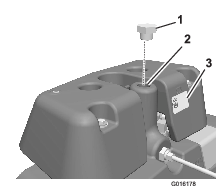
Remove and discard the breather and top off the main hydraulic tank with hydraulic fluid (Figure 10).
-
Install a plug in place of the breather (Figure 10).
-
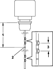
Trim the dipstick to the marked trim line shown in Figure 11. Ensure that the trimmed end is smooth; deburr the end as needed.
-
Fill the leak detector tank according to the characteristics of your leak detector tank, as follows:
-
If your leak detector tank has a sight window:
Fill the leak detector tank with hydraulic fluid until the fluid level is at the middle of the sight window.
-
If your leak detector tank does not have a sight window:
Fill the leak detector tank with hydraulic fluid until the fluid level is at the middle of the fill marks on the dipstick; refer to Figure 11.
-
-
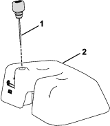
Install the dipstick on the leak detector tank (Figure 12).
-
Install the console arm cover using the hex-head screws that you previously removed.
-
Connect the battery; refer to your machine Operator’s Manual.
Checking the Leak Detector
Understanding the Leak Detector System
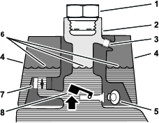
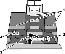
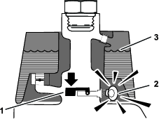
The leak detector system is designed to assist in early detection of hydraulic-fluid-system leaks. If the fluid level in the main hydraulic reservoir is lowered by 118 to 177 ml (4 to 6 fl oz), the float switch in the tank will close. After a 1 second delay, the alarm sounds, alerting the operator (Figure 15). Expansion of fluid, due to normal heating during machine operation, causes the fluid to transfer into the auxiliary fluid reservoir. The fluid returns to the main tank when you turn off the ignition switch.
Checking the System Operation
-
With the ignition switch in the ON position, move the leak detector switch rearward and hold. After the 1-second delay elapses, the alarm should sound.
-
Release the leak-detector switch.
Checking the Leak-Detector-System Operation
-
Move the ignition switch to the ON position. Do not start the engine.
-
Remove the hydraulic-tank cap from the neck of the tank.
-
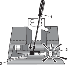
Insert a clean rod or screwdriver into the tank neck and gently push down on the float switch (Figure 16); the alarm should sound after the 1-second delay.
-
Release the float; the alarm should stop sounding.
-
Install the hydraulic-tank cap.
-
Move the ignition switch to the OFF position.
Operating the Leak Detector
The leak detector alarm may sound for 1 of the following reasons:
-
A leak of 118 to 177 ml (4 to 6 fl oz) has occurred.
-
The fluid level in the main reservoir is reduced by 118 to 177 ml (4 to 6 fl oz) due to contraction of the fluid by cooling.
If the alarm sounds, turn off the machine as quickly as possible and inspect it for leaks. If the alarm sounds while operating on a green, drive off the green first. Determine the source of the leak and repair it before continuing operation.
If you do not find a leak and suspect a false alarm, move the ignition switch to the OFF position and allow the machine to stand for 1 to 2 minutes to allow the fluid levels to stabilize. Then start the machine and operate it in a non-sensitive area to confirm that no leak exists.
False alarms, due to fluid contraction, may be caused by extended idling of the machine after normal operation. A false alarm may also occur if you work the machine at a reduced workload after an extended period of a heavier workload. To avoid false alarms, turn the machine off rather than idling for extended periods.