Warning
CALIFORNIA
Proposition 65 Warning
This product contains a chemical or chemicals known to the State of California to cause cancer, birth defects, or reproductive harm.
Setup
Preparing the Machine
-
Park the machine on a level surface.
-
Engage the parking brake.
-
Shut off the engine and remove the key.
-
Remove the seats.
-
Disconnect the battery; refer to your Operator’s Manual.
-
Raise the cargo bed to the dump position and secure it with the prop rod.
Installing the Kit
Parts needed for this procedure:
| Left loop bracket | 1 |
| Right loop bracket | 1 |
| Tube | 2 |
| Left windshield support | 1 |
| Right windshield support | 1 |
| Left, rear plate | 1 |
| Right, rear plate | 1 |
| Left, front plate | 1 |
| Right, front plate | 1 |
| Left corner gusset | 1 |
| Right corner gusset | 1 |
| Rear crosslink | 1 |
| Front crosslink | 1 |
| Backing plate | 2 |
| Crosslink tube | 2 |
| Flange nut (5/16 inch) | 38 |
| Flange nut (1/4 inch) | 4 |
| Carriage bolt (5/16 x 1-3/4 inches) | 20 |
| Hex-flange bolt (3/8 x 1 inch) | 4 |
| Flange nut (3/8 inch) | 4 |
| Hex-flange bolt (5/16 x 1 inch) | 2 |
| Carriage bolt (5/16 x 1 inch) | 4 |
| Clip | 4 |
| Sunshade | 1 |
| Sealing washer | 6 |
| Hex-flange bolt (1/4 x 1 inch) | 6 |
| Spacer (9/32 x 5/8 inch) | 2 |
| Flat washer | 2 |
| Hex-head bolt (1/4 x 2-1/2 inches) | 2 |
| Mounting plate | 2 |
| Carriage bolt (5/16 x 2 inches) | 8 |
| Plastic washer | 4 |
| Flange bushing | 2 |
| Friction washer | 2 |
| Carriage bolt (5/16 x 3/4 inch) | 4 |
| Roof-support bracket | 2 |
| Self-tapping screw (1/4 x 1/2 inch) | 2 |
| Front support | 1 |
| Hex-flange bolt (1/4 x 1-1/2 inches) | 2 |
Note: Do not tighten any fasteners except when instructed.
-
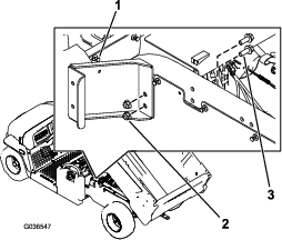
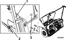
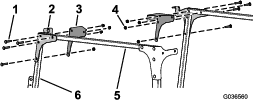
Install the left loop bracket as follows:
-
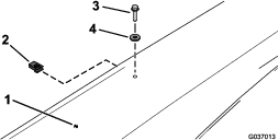
Remove the rivet from left panel behind the rear seat base (Figure 1).
-
Install the left loop bracket using 2 hex-flange bolts (3/8 x 1 inch) and 2 nuts (3/8 inch) as shown in Figure 1.
-
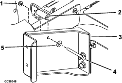
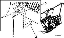
Secure the bracket behind the rear seat base using 1 hex-head bolt (1/4 x 2-1/2 inches), 1 flat washer (5/16 inch), 1 spacer (9/32 x 5/8 inch), and 1 flange nut (1/4 inch) as shown in Figure 2.
-
Repeat this step to install the right loop bracket on the right side of the machine.
-
-
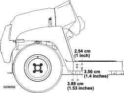
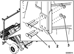
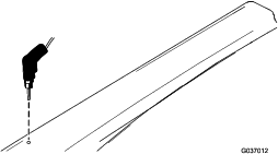
Using the dimensions shown in Figure 3, drill 2 holes (5/16 inch) into the outside of the floor plate on the left and right sides of the machine.
-
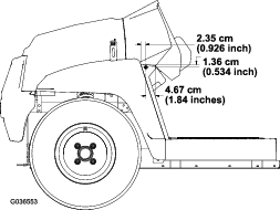
Using the dimensions shown in Figure 4, drill 1 hole (5/16 inch) into the outside of the footboard on the left and right sides of the machine.
-
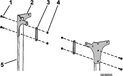
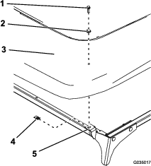
Secure the middle bracket of the windshield support to the machine using 2 hex-flange bolts (5/16 x 1 inch) and 2 nuts (5/16 inch) in the holes you drilled (Figure 5).
-
Secure the lower bracket of the windshield support to the left side of the machine using 4 carriage bolts (5/16 x 1 inch) and 4 flange nuts (5/16 inch) in the holes you drilled in step 2 (Figure 6).
-
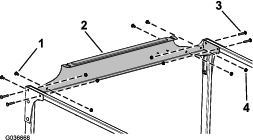
Loosely install the rear tubes to the rear loop brackets using 8 carriage bolts (5/16 x 2 inches), 2 mounting plates, and 8 nuts (5/16 inch) as shown in Figure 7.
-
Loosely install the left and right rear plates to the tubes using 4 carriage bolts (5/16 x 1-3/4 inches), 2 backing plates, and 4 flange nuts (5/16 inch) as shown in Figure 8.
-
Loosely install the left and right front plates and corner gussets to the crosslink tubes and the left and right windshield supports using 8 carriage bolts (5/16 x 1-3/4 inches) and 8 flange nuts (5/16 inch) as shown in Figure 9.
-
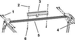
Loosely install the rear crosslink to the crosslink tubes and rear plates using 4 carriage bolts (5/16 x 1-3/4 inches), 4 carriage bolts (5/16 x 3/4 inch), and 8 flange nuts (5/16 inch) as shown in Figure 10.
-
Loosely install the front crosslink to the front plates and corner gussets using 4 carriage bolts (5/16 x 1-3/4 inch) and 4 flange nuts (5/16 inch) as shown in Figure 11.
-
Install the front support to the front crosslink using 2 hex-flange bolts (1/4 x 1-1/2 inches) and 2 flange nuts (1/4 inch) as shown in Figure 11.
-
Tighten all loose fasteners.
-
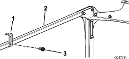
Install the 2 roof-support brackets to the crosslink tubes using 2 self-tapping screws (1/4 x 1/2 inch) as shown in Figure 12.
-
Set the sunshade down.
-
Using the hole in the top of the roof-support bracket as the template, drill a 7.9 mm (5/16 inch) hole on each side of the sunshade (Figure 13).
-
Install the sunshade to the roof-support bracket using 2 clips, 2 sealing washers, and 2 hex-flange bolts (1/4 x 1 inch) as shown in Figure 14.
-
Install the sunshade to the front plates using 2 clips, 2 sealing washers, and 2 hex-flange bolts (1/4 x 1 inch) as shown in Figure 15.
Important: Apply thread-locking compound to the hex-flange bolts (1/4 x 1 inch) before installing.
-
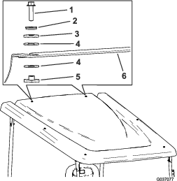
Install the sunshade to the rear crosslink using 2 hex-flange bolts (1/4 x 1 inch), 2 sealing washers, 2 friction washers, 4 plastic washers, and 2 flange bushings (Figure 16).
Important: Apply thread-locking compound to the hex-flange bolts (1/4 x 1 inch) before installing.
Important: Ensure that the plastic washers are installed onto the top and bottom of the sunshade, as this prevents damaging the sunshade.
-
Connect the battery; refer to your Operator’s Manual.