Introduction
The machine is a hydraulically powered auger attachment for Toro compact tool carriers. It is designed to dig vertical holes in earth for the installation of posts, plants, and other construction and landscaping needs. It is not intended to drill holes in pavement, concrete, or ice.
Read this information carefully to learn how to operate and maintain your product properly and to avoid injury and product damage. You are responsible for operating the product properly and safely.
You may contact Toro directly at www.Toro.com for product safety and operation training materials, accessory information, help finding a dealer, or to register your product.
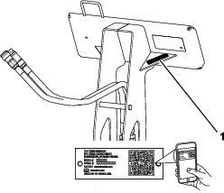
Whenever you need service, genuine Toro parts, or additional information, contact an Authorized Service Dealer or Toro Customer Service and have the model and serial numbers of your product ready. Figure 1 identifies the location of the model and serial numbers on the product. Write the numbers in the space provided.
Important: With your mobile device, you can scan the QR code on the serial number decal (if equipped) to access warranty, parts, and other product information.
This manual identifies potential hazards and has safety messages identified by the safety-alert symbol (Figure 2), which signals a hazard that may cause serious injury or death if you do not follow the recommended precautions.

This manual uses 2 words to highlight information. Important calls attention to special mechanical information and Note emphasizes general information worthy of special attention.
This product complies with all relevant European directives. For details, please see the Declaration of Incorporation (DOI) at the back of this publication.
Warning
CALIFORNIA
Proposition 65 Warning
Use of this product may cause exposure to chemicals known to the State of California to cause cancer, birth defects, or other reproductive harm.
Safety
Danger
There may be buried utility lines in the work area. Digging into them may cause a shock or an explosion.
Have the property or work area marked for buried lines and do not dig in marked areas. Contact your local marking service or utility company to have the property marked (for example, in the US, call 811 or in Australia, call 1100 for the nationwide marking service).
General Safety
Always follow all safety instructions to avoid serious injury or death.
-
Always carry the attachment close to the ground; refer to Transport Position.
-
Have the property or work area marked for buried lines and other objects, and do not dig in marked areas.
-
Read and understand the content of this Operator’s Manual before starting the engine.
-
Use your full attention while operating the machine. Do not engage in any activity that causes distractions; otherwise, injury or property damage may occur.
-
Never allow children or untrained people to operate the machine.
-
Keep your hands and feet away from the moving components and attachments.
-
Do not operate the machine without the guards and other safety protective devices in place and working on the machine.
-
Keep bystanders and pets a safe distance away from the machine.
-
Stop the machine, shut off the engine, and remove the key before servicing, fueling, or unclogging the machine.
Improperly using or maintaining this machine can result in injury.
To reduce the potential for injury, comply with these safety instructions
and always pay attention to the safety-alert symbol  , which means Caution, Warning,
or Danger—personal safety instruction. Failure to comply with
these instructions may result in personal injury or death.
, which means Caution, Warning,
or Danger—personal safety instruction. Failure to comply with
these instructions may result in personal injury or death.
You can find additional safety information where needed throughout this Operator’s Manual.
Slope Safety
-
Operate the machine up and down slopes with the heavy end of the machine uphill. Weight distribution changes with attachments. An empty attachment makes the rear of the machine the heavy end, and a full attachment makes the front of the machine the heavy end. Most other attachments make the front of machine the heavy end.
-
Keep the attachment in the lowered position when on slopes. Raising the attachment on a slope affects the stability of the machine.
-
Slopes are a major factor related to loss of control and tip-over accidents, which can result in severe injury or death. Operating the machine on any slope or uneven terrain requires extra caution.
-
Establish your own procedures and rules for operating on slopes. These procedures must include surveying the site to determine which slopes are safe for machine operation. Always use common sense and good judgment when performing this survey.
-
Slow down and use extra care on hillsides. Ground conditions can affect the stability of the machine.
-
Avoid starting or stopping on a slope. If the machine loses traction, proceed slowly, straight down the slope.
-
Avoid turning on slopes. If you must turn, turn slowly and keep the heavy end of the machine uphill.
-
Keep all movements on slopes slow and gradual. Do not make sudden changes in speed or direction.
-
If you feel uneasy operating the machine on a slope, do not do it.
-
Watch for holes, ruts, or bumps, as uneven terrain could overturn the machine. Tall grass can hide obstacles.
-
Use caution when operating on wet surfaces. Reduced traction could cause sliding.
-
Do not operate the machine near drop-offs, ditches, embankments, or bodies of water. The machine could suddenly roll over if a wheel or track goes over the edge or the edge caves in. Maintain a safe distance between the machine and any hazard.
-
Do not remove or add attachments on a slope.
-
Do not park the machine on a hillside or slope.
-
Do not pull a trailer on any slope.
Boring Unit Safety
-
For wheeled machines, do not use the counterweight on the traction unit when using the boring unit.
-
Keep at least ten feet from rotating parts, unless you are operating the rod guide tool.
-
Do not wear loose clothing or jewelry while operating or assisting with the boring unit.
-
Never use anything but the rod guide tool for starting the rod and boring bit.
-
Never use bolts or pins in place of push button connectors.
-
Always have 2 people operate the attachment, 1 to operate the traction unit and the other to guide the boring unit with the guide tool.
-
Always use the guide tool to align the boring unit.
-
Never straddle or stand on the rod when the engine is running.
Maintenance and Storage Safety
-
Check fasteners at frequent intervals for proper tightness to ensure that the equipment is in safe operating condition.
-
Refer to the Operator’s Manual for important details if you store the attachment for an extended period of time
-
Maintain or replace safety and instruction labels, as necessary.
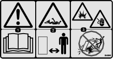
Safety and Instructional Decals
|
Safety decals and instructions are easily visible to the operator and are located near any area of potential danger. Replace any decal that is damaged or missing. |
Product Overview
Note: Specifications and design are subject to change without notice.
| Width | 61 cm (24 inches) |
| Length | 56 cm (22 inches) |
| Height | 63.5 cm (25 inches) |
| Weight | 54 kg (120 lb) |
| Boring diameter | 3.2 to 8.9 cm (1.25 to 3.5 inches) |
Attachments/Accessories
A selection of Toro approved attachments and accessories is available for use with the machine to enhance and expand its capabilities. Contact your Authorized Service Dealer or authorized Toro distributor or go to www.Toro.com for a list of all approved attachments and accessories.
To ensure optimum performance and continued safety certification of the machine, use only genuine Toro replacement parts and accessories. Replacement parts and accessories made by other manufacturers could be dangerous, and such use could void the product warranty.
Operation
Installing and Removing the Attachment
Refer to the Operator’s Manual for the traction unit for the installation and removal procedure.
Important: Before installing the attachment, position the machine on a level surface, ensure that the mount plates are free of any dirt or debris, and ensure that the pins rotate freely. If the pins do not rotate freely, grease them.
Note: Always use the traction unit to lift and move the attachment.
Warning
If you do not fully seat the quick-attach pins through the attachment mount plate, the attachment could fall off the machine, crushing you or bystanders.
Ensure that the quick-attach pins are fully seated in the attachment mount plate.
Warning
Hydraulic fluid escaping under pressure can penetrate skin and cause injury. Fluid injected into the skin must be surgically removed within a few hours by a doctor familiar with this form of injury; otherwise, gangrene may result.
-
Ensure that all hydraulic-fluid hoses and lines are in good condition and all hydraulic connections and fittings are tight before applying pressure to the hydraulic system.
-
Keep your body and hands away from pinhole leaks or nozzles that eject high-pressure hydraulic fluid.
-
Use cardboard or paper to find hydraulic leaks; never use your hands.
Caution
Hydraulic couplers, hydraulic lines/valves, and hydraulic fluid may be hot. If you contact hot components, you may be burned.
-
Wear gloves when operating the hydraulic couplers.
-
Allow the machine to cool before touching hydraulic components.
-
Do not touch hydraulic fluid spills.
Installing an Accessory
Several different rods and bits are available for use with the attachment. Contact your Authorized Service Dealer.
-
Park the machine on a level surface, lower the loader arms, and engage the parking brake (if applicable).
-
Shut off the engine, remove the key, and wait for all moving parts to stop.
-
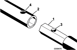
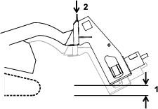
Slide the hex shaft of a rod, boring bit, or reamer into the socket. Align the hole in the socket with the push button connector (Figure 3).
-
Press down the push button connector and push the shaft into the socket until the connector snaps into the hole in the socket (Figure 3).
-
Repeat steps 3 and 4.
Removing an Accessory
-
Park the machine on a level surface, lower the loader arms, and engage the parking brake (if applicable).
-
Shut off the engine, remove the key, and wait for all moving parts to stop.
-
Press the push button connector securing the accessory shaft in the socket and pull the accessory free of the socket.
Using the Boring Unit
Digging a Trench
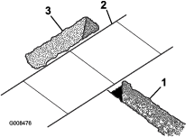
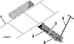
Before drilling under a walk or driveway, you must make an entrance and an exit trench on either side of the drilling area (Figure 4).
-
Both trenches must be at least 15 cm (6 inch) wide and 46 cm (18 inches) deep.
-
The entrance trench must be at least 2.13 m (7 ft) long and perpendicular to the walk or driveway.
-
The exit trench must be at least 0.91 m (3 ft) to 1.8 m (6 ft) long, parallel to the walk or driveway, and centered across from the entrance trench.
Boring a Hole
Important: Boring is a 2-person operation. Do not attempt to perform this operation by yourself.
-
Position the traction unit with the drive head at the beginning of the trench and lower it to the appropriate depth.
-
Shut off the engine, remove the key, and wait for all moving parts to stop.
-
Connect a rod and boring bit onto the drive head.
-
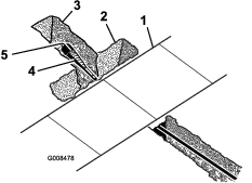
Connect the rod guide tool to the rod just behind the boring bit (Figure 5).
-
With the person guiding the boring bit positioned to the right of the trench (Figure 5), start the engine, move the pump selector valve to the SLOW position (200 and 300 series traction units only), move the throttle to midway between the SLOW and FAST positions, and pull the auxiliary hydraulics lever rearward to start the forward rotation of the boring bit.
-
Slowly move the traction unit forward, while the person with the rod-guide tool guides the boring bit into the soil (Figure 5).
-
Once the entire drill bit is in the soil, push the auxiliary hydraulics lever into neutral.
-
Shut off the engine, remove the key, and wait for all moving parts to stop.
-
If the rod is not within the grade tolerances for the job being performed, start the engine and drive backward to pull the boring bit out of the soil, then repeat steps 5 through 8, making adjustments to correct the grade.
-
Remove the rod-guide tool.
-
Start the engine and pull the auxiliary hydraulics lever rearward to start the boring bit.
-
Slowly move the traction unit forward as the boring bit digs into the soil.
Important: Do not drive too fast, forcing the bit into the soil. Allow the bit to progress at its own rate. Never push or pull the bit through the soil when the drive head is not turning.
-
When about 15 cm (6 inches) of rod are left showing in the entrance trench or when the boring bit completely enters and bores into the far side of the exit trench, stop the traction unit, push the auxiliary hydraulics lever into neutral, shut off the engine, and remove the key.
-
If the boring bit has not yet entered the exit trench, complete the following:
-
Detach the rod from the drive head.
-
Start the engine and back up to the end of the entrance trench.
-
Shut off the engine, remove the key, and wait for all moving parts to stop.
-
Connect another rod and repeat steps 11 through 14.
-
Reaming the Hole
-
Using a shovel, carefully dig around the boring bit, clearing it of soil until you can remove the bit (Figure 6).
-
Remove the boring bit and attach the reamer (Figure 6).
-
Attach the cable or piping being installed to the swivel on the end of the reamer (Figure 6).
-
Start the engine and pull the auxiliary hydraulics lever rearward to start the reamer.
-
Slowly move the traction unit rearward as the reamer digs into the soil.
Important: Do not drive too fast, forcing the reamer into the soil. Allow the reamer to progress at its own rate. Never push or pull the reamer through the soil when the drive head is not turning.
-
When a rod coupling is about 15 cm (6 inches) into the entrance trench or when the reamer completely enters the trench with about 15 cm (6 inches) of the cable or piping, stop the traction unit, pull the auxiliary hydraulics lever into neutral, shut off the engine, and remove the key.
-
If the reamer has not yet entered the exit trench, complete the following:
-
Detach the rod from the drive head and rod still in the soil.
-
Start the engine and move to the front of the entrance trench.
-
Shut off the engine, remove the key, and wait for all moving parts to stop.
-
Connect the drive head to the rod shaft in the soil.
-
Repeat steps 4 through 7.
-
-
With the reamer and cable/piping in the entrance trench, remove the cable or piping from the reamer.
Transport Position
When transporting the attachment, raise the loader arms slightly, no more than 15 cm (6 inches) above the lowest position. Tilt the attachment so that the attachment plate is vertical.
Storage
-
Before long-term storage, wash the attachment with mild detergent and water to remove dirt and grime.
-
Check the condition of the teeth. Turn or replace any worn or damaged teeth.
-
Check and tighten all bolts, nuts, and screws. Repair or replace any damaged or worn part.
-
Ensure that all hydraulic couplers are connected together to prevent contamination of the hydraulic system.
-
Paint all scratched or bare metal surfaces. Paint is available from your Authorized Service Dealer.
-
Store the attachment in a clean, dry garage or storage area. Cover it to protect it and keep it clean.
Troubleshooting
| Problem | Possible Cause | Corrective Action |
|---|---|---|
| The bore drive head does not rotate. |
|
|