Introduction

This machine is designed for use on Toro compact tool carriers to grind and remove tree stumps and surface roots. It is not intended to cut rock or any other material other than wood and the soil around a stump.

Read this information carefully to learn how to operate and maintain your product properly and to avoid injury and product damage. You are responsible for operating the product properly and safely.

You may contact Toro directly at www.Toro.com for product safety and operation training materials, accessory information, help finding a dealer, or to register your product.

Whenever you need service, genuine Toro parts, or additional information, contact an Authorized Service Dealer or Toro Customer Service and have the model and serial numbers of your product ready. Figure 1 identifies the location of the model and serial numbers on the product. Write the numbers in the space provided.

Important: With your mobile device, you can scan the QR code on the serial number decal (if equipped) to access warranty, parts, and other product information.

g245347

This manual identifies potential hazards and has safety messages identified by the safety-alert symbol (Figure 2), which signals a hazard that may cause serious injury or death if you do not follow the recommended precautions.

g000502

This manual uses 2 words to highlight information. Important calls attention to special mechanical information and Note emphasizes general information worthy of special attention.

This product complies with all relevant European directives. For details, please see the Declaration of Incorporation (DOI) at the back of this publication.

Warning

CALIFORNIA

Proposition 65 Warning

Use of this product may cause exposure to chemicals known to the State of California to cause cancer, birth defects, or other reproductive harm.

Safety

Danger

There may be buried utility lines in the work area. Digging into them may cause a shock or an explosion.

Have the property or work area marked for buried lines and do not dig in marked areas. Contact your local marking service or utility company to have the property marked (for example, in the US, call 811 or in Australia, call 1100 for the nationwide marking service).

General Safety

Always follow all safety instructions to avoid serious injury or death.

  • Always carry the attachment close to the ground; refer to Transport Position.

  • Have the property or work area marked for buried lines and other objects, and do not dig in marked areas.

  • Read and understand the content of this Operator’s Manual before starting the engine.

  • Use your full attention while operating the machine. Do not engage in any activity that causes distractions; otherwise, injury or property damage may occur.

  • Never allow children or untrained people to operate the machine.

  • Keep your hands and feet away from the moving components and attachments.

  • Do not operate the machine without the guards and other safety protective devices in place and working on the machine.

  • Keep bystanders and pets a safe distance away from the machine.

  • Stop the machine, shut off the engine, and remove the key before servicing, fueling, or unclogging the machine.

Improperly using or maintaining this machine can result in injury. To reduce the potential for injury, comply with these safety instructions and always pay attention to the safety-alert symbol, which means Caution, Warning, or Danger—personal safety instruction. Failure to comply with these instructions may result in personal injury or death.

You can find additional safety information where needed throughout this Operator’s Manual.

Slope Safety

  • Operate the machine up and down slopes with the heavy end of the machine uphill. Weight distribution changes with attachments. This attachment makes the front of machine the heavy end.

  • Keep the attachment in the lowered position when on slopes. Raising the attachment on a slope affects the stability of the machine.

  • Slopes are a major factor related to loss of control and tip-over accidents, which can result in severe injury or death. Operating the machine on any slope or uneven terrain requires extra caution.

  • Establish your own procedures and rules for operating on slopes. These procedures must include surveying the site to determine which slopes are safe for machine operation. Always use common sense and good judgment when performing this survey.

  • Slow down and use extra care on hillsides. Ground conditions can affect the stability of the machine.

  • Avoid starting or stopping on a slope. If the machine loses traction, proceed slowly, straight down the slope.

  • Avoid turning on slopes. If you must turn, turn slowly and keep the heavy end of the machine uphill.

  • Keep all movements on slopes slow and gradual. Do not make sudden changes in speed or direction.

  • If you feel uneasy operating the machine on a slope, do not do it.

  • Watch for holes, ruts, or bumps, as uneven terrain could overturn the machine. Tall grass can hide obstacles.

  • Use caution when operating on wet surfaces. Reduced traction could cause sliding.

  • Do not operate the machine near drop-offs, ditches, embankments, or bodies of water. The machine could suddenly roll over if a wheel or track goes over the edge or the edge caves in. Maintain a safe distance between the machine and any hazard.

  • Do not remove or add attachments on a slope.

  • Do not park the machine on a hillside or slope.

Stump Grinder Safety

  • For wheeled machines, do not use the counterweight on the traction unit when using the stump grinder.

  • Never operate the stump grinder without the shield installed on the traction unit and the chip guard on the grinder.

  • Keep all bystanders at least 9 m (30 ft) away from the work area.

  • Only use the stump grinder for grinding stumps less than 91 cm (36 inch) tall.

Maintenance and Storage Safety

  • Check fasteners at frequent intervals for proper tightness to ensure that the equipment is in safe operating condition.

  • Refer to the Operator’s Manual for important details if you store the attachment for an extended period of time

  • Maintain or replace safety and instruction labels, as necessary.

Safety and Instructional Decals

Graphic

Safety decals and instructions are easily visible to the operator and are located near any area of potential danger. Replace any decal that is damaged or missing.

decal136-5814
decal136-5817
decal136-5818

Setup

Preparing the Traction Unit

  1. Park the machine on a level surface.

  2. Lower the loader arms.

  3. Engage the parking brake (if applicable).

  4. Shut off the engine and remove the key.

Installing the Shield Brackets

Parts needed for this procedure:

Right shield bracket (3 holes)—200/300 Series or TX 400/500 Series only1
Left shield bracket (3 holes)—200/300 Series or TX 400/500 Series only1
Self-tapping screw (5/16 x 3/4 inch)4
Right shield bracket (2 holes)—TX 1000 only1
Left shield bracket (2 holes)—TX 1000 only1
Bolt (1/4 x 3/4 inch)—TX 1000 only4
Locknut (1/4 inch)—TX 1000 only4

200 or 300 Series Traction Unit Only

Important: Use the shield brackets with 3 holes.

  1. Insert the tab on the shield bracket into the lift-point hole on the traction unit, with the hole in the bracket aligning with the small hole in the traction unit frame (Figure 3).

    Note: There is a right and left bracket. Ensure that you install the correct bracket on each side. The tab should be in the lift-point hole and the bracket should be on the outside of the frame (Figure 3).

    g013653
  2. Secure the bracket to the frame with a self-tapping screw (Figure 3).

  3. Repeat steps 1 and 2 for the other side of the traction unit.

TX 400 or 500 Series Traction Unit Only

Important: Use the shield brackets with 3 holes.

  1. Measure in from the edges of the frame as illustrated in Figure 4 and mark the locations of the holes for mounting the shield bracket.

    Note: If the holes exist, skip to step 3.

    g203568
  2. Drill a hole (5/16 inch) through the frame at each marked location.

  3. Align the tab on the shield bracket with the front edge of the frame with the bracket inside of the loader-arm pocket (Figure 5).

    Note: There is a right and left bracket. Ensure that you install the correct bracket on each side. The tab should be over the frame edge and the bracket should be inside the loader-arm pocket with the 2 smaller holes in the bracket lined up with the holes you drilled in the frame (Figure 5).

    g013655
  4. Secure the bracket to the frame with 2 self-tapping screws as illustrated in Figure 5.

  5. Repeat steps 1 through 4 for the other side of the traction unit.

TX 1000 Traction Unit Only

Important: Use the shield brackets with 2 holes.

  1. Measure in from the edges of the frame as illustrated in Figure 6 and mark the locations of the holes for mounting the shield bracket.

    Note: If the holes exist, skip to step 3.

    g245655
  2. Drill a hole (9/32 inch) through the frame at each marked location.

  3. Install the left shield bracket on the left frame using 2 bolts (1/4 x 3/4 inch) and 2 Locknuts (1/4 inch) as shown in Figure 7.

    g202825
  4. Install the right shield bracket on the right frame 2 bolts (1/4 x 3/4 inch) and 2 locknuts (1/4 inch), similar to Figure 7.

Assembling the Operator Shield

Parts needed for this procedure:

Shield support (1 bend)—200/300 Series or TX 400/500 Series2
Shield support (2 bends)—TX 1000 only2
Shield1
Bolt (1/4 x 1-1/2 inch)8
Washer8
Locknut (1/4 inch)8

Assembling the Shield

Note: Use the shield supports with 1 bend for 200/300 series or TX 400/500 series traction units. Use the shield supports with 2 bends for TX 1000 traction units.

  1. Slide the shield supports into the pockets in the shield brackets on the traction unit (Figure 8 or Figure 9).

    g202610
    g202842
  2. Assemble the shield and flexible skirt to the shield supports as illustrated in Figure 8 or Figure 9, using 8 bolts (1/4 x 1-1/2 inch), 8 washers, and 8 locknuts (1/4 inch).

    Note: The skirt should drape over the engine or hood.

Installing the Chip Guard

Parts needed for this procedure:

Chip guard1
Guard pin1
Hairpin cotter1

The stump grinder has 4 sets of mounting holes for positioning the chip guard (Figure 10). Move the guard up (upper holes) when you are grinding close to the ground and down (lower holes) when you are chipping tall stumps. Install the chip guard as follows:

  1. Position the mounting tube on the guard between 2 holes on the grinder (Figure 10).

    g202609
  2. Slide the guard pin through the holes in the grinder and the mounting tube (Figure 10).

  3. Secure the pin with a hairpin cotter (Figure 10).

Product Overview

g013651

Note: Specifications and design are subject to change without notice.

Width (with chip guard)112 cm (44 inches)
Width (without chip guard)66 cm (26 inches)
Length51 cm (20 inches)
Height79 cm (31 inches)
Weight120 kg (265 lb)

Attachments/Accessories

A selection of Toro approved attachments and accessories is available for use with the machine to enhance and expand its capabilities. Contact your Authorized Service Dealer or authorized Toro distributor or go to www.Toro.com for a list of all approved attachments and accessories.

To ensure optimum performance and continued safety certification of the machine, use only genuine Toro replacement parts and accessories. Replacement parts and accessories made by other manufacturers could be dangerous, and such use could void the product warranty.

Operation

Installing and Removing the Attachment

Refer to the Operator’s Manual for the traction unit for the installation and removal procedure.

Important: Before installing the attachment, position the machine on a level surface, ensure that the mount plates are free of any dirt or debris, and ensure that the pins rotate freely. If the pins do not rotate freely, grease them.

Note: Always use the traction unit to lift and move the attachment.

Warning

If you do not fully seat the quick-attach pins through the attachment mount plate, the attachment could fall off the machine, crushing you or bystanders.

Ensure that the quick-attach pins are fully seated in the attachment mount plate.

Warning

Hydraulic fluid escaping under pressure can penetrate skin and cause injury. Fluid injected into the skin must be surgically removed within a few hours by a doctor familiar with this form of injury; otherwise, gangrene may result.

  • Ensure that all hydraulic-fluid hoses and lines are in good condition and all hydraulic connections and fittings are tight before applying pressure to the hydraulic system.

  • Keep your body and hands away from pinhole leaks or nozzles that eject high-pressure hydraulic fluid.

  • Use cardboard or paper to find hydraulic leaks; never use your hands.

Caution

Hydraulic couplers, hydraulic lines/valves, and hydraulic fluid may be hot. If you contact hot components, you may be burned.

  • Wear gloves when operating the hydraulic couplers.

  • Allow the machine to cool before touching hydraulic components.

  • Do not touch hydraulic fluid spills.

Grinding Stumps

Warning

During operation, debris fly in all directions and can cause injury to eyes and other exposed body parts.

  • Never operate the stump grinder without the shield installed on the traction unit and the chip guard on the grinder.

  • During operation, wear eye protection, hearing protection, substantial, slip-resistant footwear, and long pants.

  • Keep all bystanders at least 9 m (30 ft) away from the work area.

  1. If your traction unit has a speed selector, move it to the SLOW position.

  2. Start the engine.

  3. Pull the auxiliary hydraulics lever to the operator grip to engage the stump grinder.

  4. Position the grinder on the left side and behind the stump (Figure 12).

    g013658
  5. Swing the grinder toward you using the attachment-tilt lever, grinding at a depth of 0.5 to 5 cm (1/4 to 2 inches), depending on the hardness of the wood (Figure 12).

    Note: If you cut too deep, the grinder stalls. If it stalls, raise it slightly and try again.

  6. Swing the grinder back out (Figure 12), lower it 0.5 to 5 cm (1/4 to 2 inches), and repeat steps 4 through 6 until you have ground down a few inches.

  7. Raise the loader arms to the original height.

  8. Move the grinder to the right (Figure 12).

  9. Repeat steps 4 through 8 until you reach the right side of the stump.

  10. Return the grinder to the left side of the stump, lower it, and repeat steps 3 through 10 until you have ground the stump into the ground.

    Note: To contain the chips, you may need to stop the grinder and move the chip guard up as you move the grinder down.

  11. When finished, stop the grinder by moving the auxiliary hydraulics lever to the NEUTRAL position.

Grinding Roots

  1. Stop the grinder and hang it vertically from the loader arms a few centimeters (inches) off the ground.

  2. Shut off the engine and remove the key.

  3. Loosen the large bolt on the top of the grinder (Figure 13).

    g013659
  4. Remove the front bolt and nut securing the grinder (Figure 13).

  5. Swing the grinder 30 degrees clockwise (Figure 13).

  6. Torque the large bolt on top of the grinder to 406 N∙m (300 ft-lb) as shown in Figure 13.

  7. Install the bolt and nut in the front hole and torque them to 101 N∙m (75 ft-lb) as shown in Figure 13.

  8. Start the traction unit and start the grinder.

  9. Lower the grinder into the root.

  10. Move the grinder along the length of the root by moving the traction unit over the root.

  11. When finished, stop the grinder by moving the auxiliary hydraulics lever to the NEUTRAL position.

  12. Shut off the engine and remove the key.

  13. Loosen the large bolt on the top of the grinder (Figure 13).

  14. Remove the front bolt and nut securing the grinder (Figure 13).

  15. Swing the grinder 30 degrees counter-clockwise (Figure 13).

  16. Torque the large bolt on top of the grinder to 406 N∙m (300 ft-lb) as shown in Figure 13.

  17. Install the bolt and nut in the front hole and torque them to 101 N∙m (75 ft-lb) as shown in Figure 13.

Transport Position

When transporting the attachment, keep it as close to the ground as possible, no more than 15 cm (6 inches) above the lowest position. Tilt it rearward.

g245446

Transporting the Stump Grinder on a Trailer

Place the attachment on a trailer or truck capable of carrying it. Securely tie it to the trailer or truck using tie straps appropriate for the weight of the attachment and for highway use.

Important: Remove the operator's shield before transporting the traction unit to avoid damage to the shield of the traction unit.

Operating Tips

  • Always use full throttle (maximum engine speed).

  • Never transport the attachment with the loader arms raised. Keep the arms lowered and the attachment tilted up.

  • If your traction unit has a speed selector (present on some wheeled traction units), set it to the SLOW (turtle) position.

  • If your traction unit has a flow divider (present on some wheeled traction units), adjust it to approximately the 10 o’clock position.

Maintenance

Recommended Maintenance Schedule(s)

Maintenance Service IntervalMaintenance Procedure
Before each use or daily
  • Grease the machine.
  • Check the condition of the teeth and rotate or replace any that are worn or damaged.
  • Before storage
  • Grease the machine.
  • Paint chipped surfaces.
  • Greasing the Machine

    Maintenance Service IntervalMaintenance Procedure
    Before each use or daily
  • Grease the machine.
  • Before storage
  • Grease the machine.
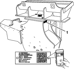
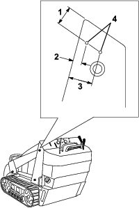
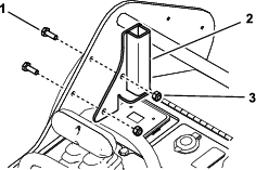
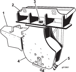
  • Grease the fitting in Figure 15.

    g203602

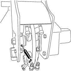
    Grease Type: General-purpose grease

    1. Park the machine on a level surface, lower the loader arms, and engage the parking brake (if applicable).

    2. Shut off the engine and remove the key.

    3. Clean the grease fitting with a rag.

    4. Connect a grease gun to the fitting.

    5. Pump grease into the fitting until grease begins to ooze out of the bearings.

    6. Wipe up any excess grease.

    Replacing the Teeth

    Maintenance Service IntervalMaintenance Procedure
    Before each use or daily
  • Check the condition of the teeth and rotate or replace any that are worn or damaged.
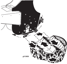
  • Due to the high amount of wear placed on the teeth, you will need to rotate and replace them periodically.

    Each tooth is indexed with 3 positions so that you can rotate it twice, exposing a new sharp edge before replacing the tooth.

    g034325

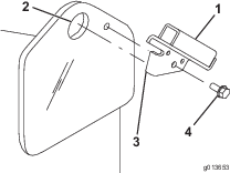
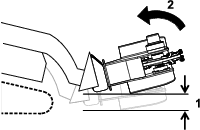
    To rotate a tooth, loosen the nut securing the tooth (Figure 17). Push the tooth forward and rotate it one third of a turn, bringing an unused edge to the outside. Torque the nut securing the tooth to 37 to 45 N∙m (27 to 33 ft-lb).

    g246708

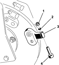
    To replace a tooth, remove the nut securing the tooth to remove it, then install a new tooth and nut in the same position (Figure 17). Torque the nut securing the tooth to 37 to 45 N∙m (27 to 33 ft-lb).

    Storage

    1. Before long-term storage, wash the attachment with mild detergent and water to remove dirt and grime.

    2. Check the condition of the teeth. Turn or replace any worn or damaged teeth.

    3. Check and tighten all bolts, nuts, and screws. Repair or replace any damaged or worn part.

    4. Ensure that all hydraulic couplers are connected together to prevent contamination of the hydraulic system.

    5. Paint all scratched or bare metal surfaces. Paint is available from your Authorized Service Dealer.

    6. Store the attachment in a clean, dry garage or storage area. Cover it to protect it and keep it clean.

    Troubleshooting

    ProblemPossible CauseCorrective Action
    The cutting disk stops during cutting.
    1. You are cutting too deep.
    2. Teeth are worn, damaged, or broken.
    1. Raise the loader arms 13 mm (1/2 inch).
    2. Rotate or replace any worn, damaged, or broken teeth.
    The cutting disk does not turn or turns slowly.
    1. A hydraulic coupler is not completely connected.
    2. A hydraulic coupler is damaged.
    3. There is an obstruction in a hydraulic hose.
    4. An auxiliary valve on the traction unit is not opening.
    5. The hydraulic motor or drive has failed.
    6. The check valve brake is reversed.
    1. Check and tighten all couplers.
    2. Check/replace couplers.
    3. Find and remove the obstruction.
    4. Repair the valve.
    5. Contact your Authorized Service Dealer.
    6. Reverse the check valve direction; contact your Authorized Service Dealer.
    The grinder does not cut fast enough.
    1. Teeth are worn.
    2. The setting is wrong on the flow divider and speed lever (applicable wheeled units only).
    3. There is a restriction in a quick coupler or hose.
    4. The hydraulic system is too hot.
    5. The relief valve is set below specifications.
    1. Rotate or replace any worn teeth.
    2. Set the flow divider to the 10 o’clock position and the speed lever to the turtle position.
    3. Check the hoses and couplers and repair any problems found.
    4. Shut the system down and allow it to cool.
    5. Contact your Authorized Service Dealer.
    The cutting disk turns in the wrong direction.
    1. The auxiliary-valve lever is in the wrong position.
    2. The hydraulic hoses are reversed.
    1. Move the auxiliary-valve lever to the rearward position.
    2. Disconnect the hoses and switch positions.