Warning
CALIFORNIA
Proposition 65 Warning
This product contains a chemical or chemicals known to the State of California to cause cancer, birth defects, or reproductive harm.
Setup
Preparing the Machine
-
Park the machine on a level surface.
-
Engage the parking brake.
-
Shut off the engine and remove the key.

Installing the Side Mirror Kit
Parts needed for this procedure:
| Upper mirror bracket | 1 |
| Lower mirror bracket | 1 |
| Mirror mount | 1 |
| Bolt (5/16 x 3/4 inch) | 2 |
| Flange nut (5/16 inch) | 2 |
| Mirror | 1 |
| Pan-head screw (1/4 x 1 inch) | 4 |
| Nut insert | 4 |
-
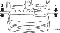
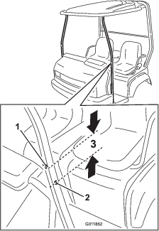
To install a mirror on the left side of the machine (driver’s side), measure 4.45 cm (1-3/4 inches) out from the edge of the dash panel, and draw a parallel line to the edge (Figure 2).
If a 4-post ROPS is installed on the machine, measure 5.1 cm (2 inches) instead of 4.45 cm (1-3/4 inches).
To install a mirror on the right side of the machine (passenger’s side), measure 5.56 cm (2-3/16 inches) out from the edge of the dash panel, and draw a parallel line to the edge (Figure 2).
-
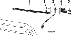
Assemble the mirror mount to the lower and upper mirror brackets using the 2 bolts (5/16 x 3/4 inch) and 2 flange nuts (5/16 inch) as shown in Figure 3.
-
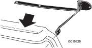
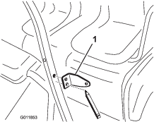
Position the upper mirror bracket holes onto the parallel line drawn on the dash (Figure 4).
Ensure that the lower mirror bracket is contacting the side of the machine.
-
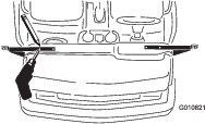
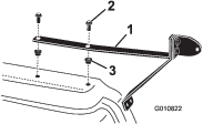
Using the upper mirror bracket as a template, locate, mark, and drill 2 holes (12.7 mm or 1/2-inch) diameter into the dash (Figure 5).
-
Install a nut insert into each of the drilled holes (Figure 6).
-
Secure the upper mirror bracket to the nut inserts using 2 Pan-head screw (1/4 x 1 inch) as shown in Figure 6.
-
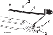
Using the lower mirror bracket as a template, locate, mark, and drill 2 holes (12.7 mm or 1/2-inch) diameter into the side of the machine (Figure 7).
-
Remove the screws securing the upper mirror bracket to the dash and remove the mounts.
-
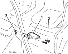
Install a nut insert into each of the drilled holes (Figure 8).
-
Secure the upper and lower mirror brackets to the nut inserts using 4 pan-head screws (1/4 x 1 inch) as shown in Figure 8.
-
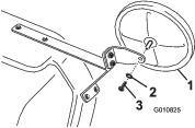
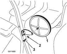
Secure the mirror to the mirror mount using the supplied screw and washer (Figure 9).
-
Adjust the mirror(s) to the desired position.
Installing the Side Mirror Kit
Parts needed for this procedure:
| Mirror mount | 1 |
| Bolt (5/16 x 1-1/2 inches) | 2 |
| Flange nut (5/16 inch) | 2 |
-
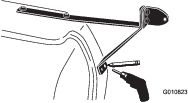
Locate the windshield mounting holes in the front canopy support tubes (Figure 10).
-
On the side of the tube that you are going to mount the mirror, measure down 2.54 cm (1 inch) from the windshield mounting hole and make a mark in the center of the tube (Figure 10).
-
At the marked location, drill a 8.3 mm (5/16 inch) diameter hole through both walls of the tube (Figure 10).
-
Position the mirror mount onto the tube, aligning the top hole with the new hole in the tube (Figure 11).
-
Using the mirror mount as a template, locate, mark, and drill the lower 8.3 mm (5/16 inch) diameter hole through both walls of the tube (Figure 11).
-
Secure the mirror mount to the tube using 2 bolts (5/16 x 1-1/2 inches) and 2 flange nuts (5/16 inch) as shown in Figure 12.
-
Secure the mirror to the mirror mount using the supplied screw and washer (Figure 13).
-
Adjust the mirror(s) to the desired position.