
Maintenance
Recommended Maintenance Schedule(s)
| Maintenance Service Interval | Maintenance Procedure |
|---|---|
| After the first 10 operating hours |
|
| After the first 250 operating hours |
|
| Every 50 hours |
|
| Every 200 hours |
|
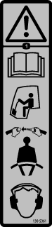
Warning
If you leave the key in the ignition switch, someone could accidently start the engine and seriously injure you or bystanders.
Remove the key from the ignition switch before you do any maintenance.
Lubrication
Greasing and Lubricating the Machine
-
Move the machine to a level surface, disengage the PTO, and set the parking brake.
-
Shut off the engine, remove the key from the ignition, and wait for all moving parts to stop before you leave the operating position.
-
Clean the grease fittings with a rag.
Note: Remove any paint off the front of the fitting.
-
Connect a grease gun to the fitting and pump grease into the fittings until grease begins to ooze out of the bearings.
-
Wipe clean excess grease.
Electrical System Maintenance
Important: Whenever working with the electrical system, always disconnect the battery cables, negative (-) cable first, to prevent possible wiring damage from short-outs.
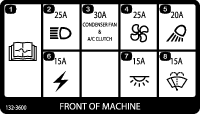
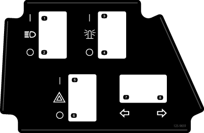
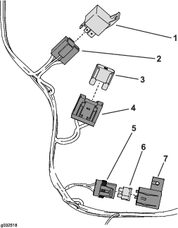
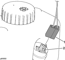
Checking the Fuses
Refer to the Operator's Manual supplied with the cab for instructions on fuses.
If the machine has any electrical system issues, check the fuses. One at a time, remove each fuse from the fuse block and check the fuse to determine if it is open (blown). If you need to replace a fuse, always use the same type and amperage rated fuse as the fuse you are replacing, otherwise you may damage the electrical system.
Note: If a fuse blows frequently, you may have a short in the electrical system and should have it serviced by a qualified service technician.
Drive System Maintenance
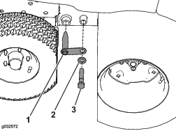
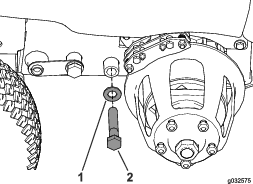
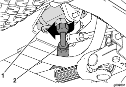
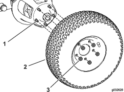
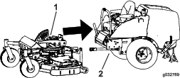
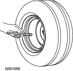
Checking the Tire Pressure
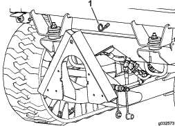
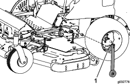
Important: Check the air pressure in the tires before the machine is operated.
Check that the air pressure tires is 240 kPa (35 psi); refer to Figure 131.
Note: Uneven air pressure in the tires can cause loss of traction. If the machine losses traction, increase air pressure in the tire to 344 kPa (50 psi) to increase track tension.
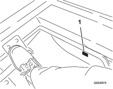
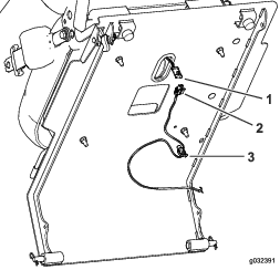
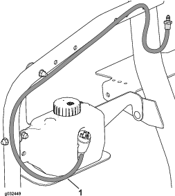
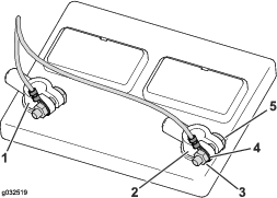
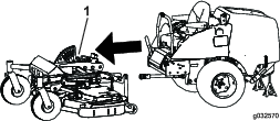
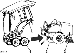
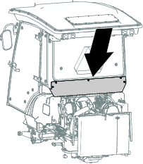
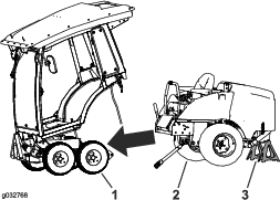
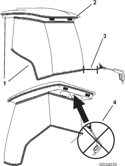
Cleaning the Cab
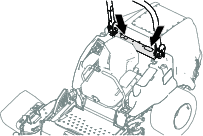
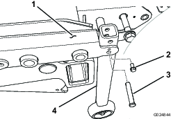
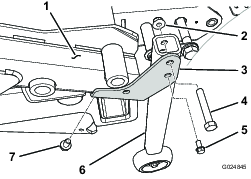
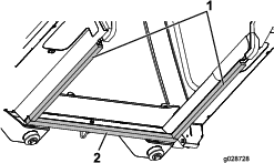
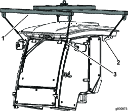
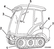
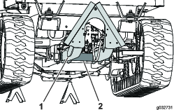
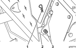
Important: Use care around the cab seals and lights (Figure 132). If you are using a pressure washer, keep the washer wand at least 0.6 m (2 ft) away from the machine. Do not use the pressure washer directly on the cab seals and lights or under the rear overhang.
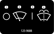
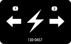
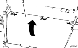
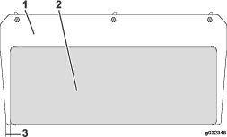
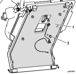
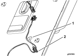
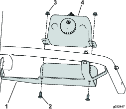
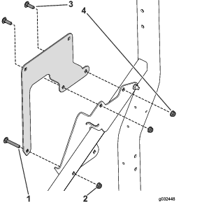
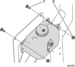
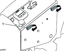
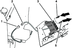
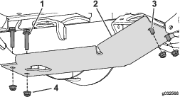
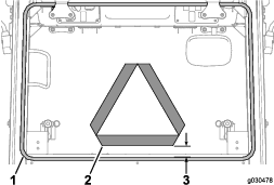
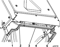
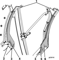
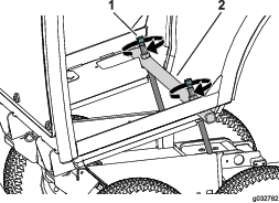
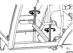
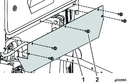
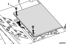
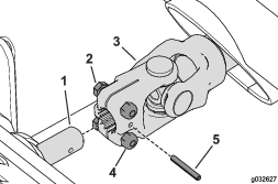
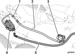
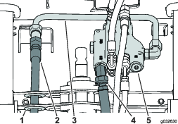
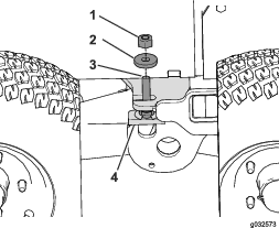
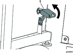
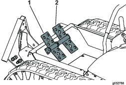
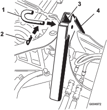
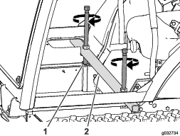
Cleaning the Air Filters
-
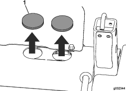
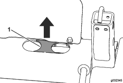
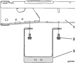
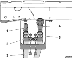
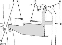
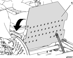
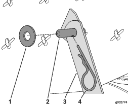
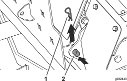
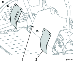
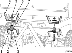
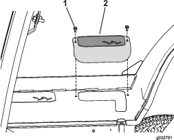
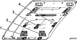
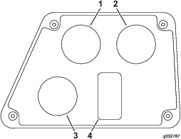
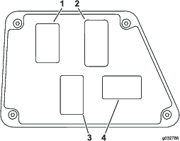
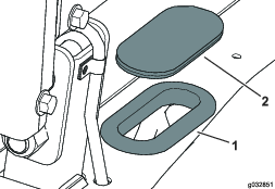
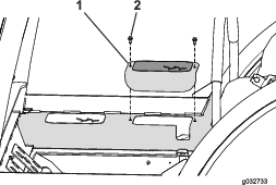
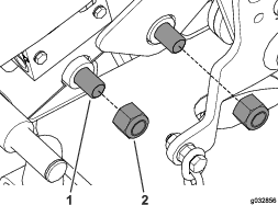
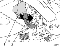
Remove the thumb screws and the grates from both the in-cab and rear cab air filters (Figure 133 and Figure 134).
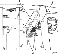
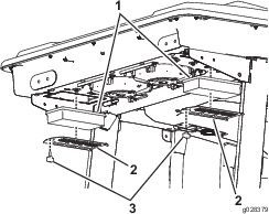
-
Clean the filters by blowing clean, oil free, compressed air through them.
Important: If either filter has a hole, tear, or other damage, replace it.
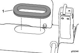
-
Install the filters and grate, securing them with the thumb screws.