Setup
Note: Determine the left and right sides of the machine from the normal operating position.
Removing the Machine from the Crate
If removing the machine from a metal crate, refer to the Dealer/Distributor Portal for further information.
Adding Fuel to the Machine
Add fuel to the machine before starting it. Refer to your Operator’s Manual for the correct fuel and procedure.
Checking the Engine-Oil Level
Before you start the engine and use the machine, check the oil level in the engine crankcase; refer to Servicing the Engine-Oil Level in the Operator's Manual.
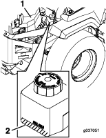
Servicing the Hydraulic Fluid
This machine is shipped filled with hydraulic fluid in the reservoirs.
Check the expansion tank; if necessary, add Toro® HYPR-OIL ™ 500 hydraulic fluid, as recommended in the Operator's Manual, to the FULL COLD line (Figure 1).
Checking the Tire Pressure
Pressure: 13 psi (90 kPa)
Note: Check the tire pressure before starting the machine. Refer to your Operator’s Manual for the correct tire type and procedure.
Servicing the Battery
Important: Do not run the machine with the battery disconnected; electrical damage may occur to the engine.
-
Charge the battery. Refer to the Operator's Manual for instructions.
-
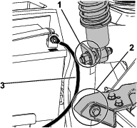
Connect the negative battery cable.
Note: If the positive cable is also disconnected, connect the positive (red) cable to the positive battery terminal first, then the negative (black) cable to the negative battery terminal. Slip the insulator boot over the positive terminal.
Note: For MyRide machines, ensure that the ground cable does not rub against the trailing arm or lower shock mount (Figure 2).
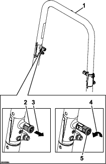
Raising the Rollover Protection System (ROPS)
-
Pull both knobs out and rotate them 90 degrees so that they are not engaged (Figure 3).
-
Raise the roll bar to the operating position and rotate the knobs until they move partially into the grooves (Figure 3).
-
Raise the roll bar to the full upright position while pushing on the upper roll bar so that the pins snap into position when the holes align with the pins.
-
Push on the roll bar and ensure that both pins are engaged (Figure 3).
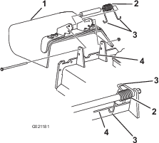
Checking the Grass Deflector
If there are plastic ties holding the grass deflector up, remove them and lower the deflector into place.
Warning
An uncovered discharge opening could allow the machine to throw objects toward you or bystanders, resulting in serious injury or death. Also, contact with the blade could occur.
Never operate the machine without a cover plate, a mulch plate, grass deflector, or bagger installed.
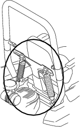
-
Make sure that 1 end of the spring is installed behind the deck edge before installing the bolt as shown in Figure 4.
-
Place the other end of the spring around grass deflector (Figure 4).
Important: The grass deflector must be free to rotate with downward tension. Lift the deflector up to the full open position and ensure that it rotates freely, without binding into the full down position.
Removing the Shipping Strap(s)
Note: This procedure is only for machines with a MyRide ™ suspension system.
Warning
The springs are compressed by the shipping strap(s). When the strap(s) are removed, the seat will raise up quickly by approximately 8.9 cm (3-1/2 inches).
Note: Ensure the strap(s) are removed in the area shown in Figure 5 before operating the machine.
Checking the Machine for Grease
Parts needed for this procedure:
| No. 2 lithium or molybdenum-based grease (purchase separately) | 1 tube |
Before you use the machine, check the machine for grease; refer to Lubrication in the Operator's Manual.
Installing the Right Bumper
Parts needed for this procedure:
| Locknut (3/8 inch) | 3 |
| Carriage bolt (3/8 x 2-1/4 inches) | 3 |
Mount the side bumpers in the top holes when operating in height of cut higher than 64 mm (2-1/2 inches) and in the center holes when operating in height of cut lower than 64 mm (2-1/2 inches).
-
Raise the mower deck to the 12.7 cm (5 inch) height position (also the transport position).
-
The right bumper is secured to the machine with a cable tie for shipping. Remove and discard the cable ties.
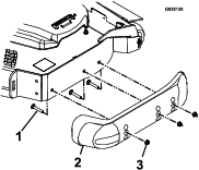
-
Move each bumper to the desired position and secure it with 3 carriage bolts (3/8 x 2-1/4 inches) and 3 locknuts (3/8 inch).
-
Torque the bolts to 14 to 16 N∙m (10 to 12 ft-lb).
Checking the Mower Adjustment
Adjust the side-to-side level and the front-to-rear blade slope. Use the relevant procedures in the Operator's Manual to verify that the deck is level, and make any adjustments as needed.
Checking the Machine Before Delivery to the Customer (All Machines)
Before delivering the machine to the customer, ensure that you have performed the procedures listed in the following table and initial each when finished. Refer to the Operator's Manual for instructions on performing these procedures.
| Initial | Check Procedure |
| Check the tire pressure. | |
| Check the level of the mower deck. | |
| Check the engine-oil level. | |
| Check the hydraulic-fluid level. | |
| Check that the ROPS is secure. | |
| Check the adjustment of the parking brake. | |
| Ensure that the machine tracks correctly; refer to the Operator's Manual for the adjustment procedure. | |
| Check the safety interlock system; refer to the Operator's Manual. | |
| Ensure that the PTO works. | |
| Check all fasteners that you installed to ensure that they are tight. |
When you finish setting up the machine, sign and date in the space provided below:
Delivering the Machine to the Customer (All Machines)
Parts needed for this procedure:
| Operator's Manual | 1 |
| Engine owner's manual (non-Toro engines) | 1 |
| Operator-training material | 1 |
| Key | 2 |
| Registration card | 1 |
At delivery, fill in the model and serial number, complete the items listed in the following table, and initial each when finished.
| Dealer Initial | Customer Initial | Check Procedure | ||
|---|---|---|---|---|
| Show the customer where the following features are located and how they function: | ||||
| Fuel tank | ||||
| Oil-fill cap/Oil dipstick | ||||
| Spark plug(s) | ||||
| Engine-oil filter | ||||
| Engine-oil drain | ||||
| Fuel gauge, valve, and hose | ||||
| Air filter | ||||
| Hydraulic-fluid reservoir | ||||
| Hydraulic filter | ||||
| Battery | ||||
| Ignition switch | ||||
| Throttle lever | ||||
| Choke (if applicable) | ||||
| Power takeoff switch (PTO) | ||||
| Motion-control levers | ||||
| Parking brake | ||||
| Height of cut | ||||
| Lift-assist lever (if applicable) | ||||
| Adjustable seat | ||||
| Hydraulic-bypass valves | ||||
| Rollover Protection System (ROPS) | ||||
| Refer to the Operator's Manual to point out safety procedures, operation, and maintenance procedures. | ||||
| Review the warranty statement as shown in the Operator's Manual. | ||||
| Describe the post-sale service procedures for your store. | ||||
| Assist the customer in filling out and mailing the registration card or register online at www.Toro.com. | ||||
| Make sure that the customer receives the Operator's Manual, engine owner's manual (non-Toro engines), Set Up Instructions, and operator training material. | ||||
| Make sure the customer knows that the Parts Catalog is available at www.Toro.com. | ||||
| Assist the customer in loading the machine. | ||||
Note: When you, the dealer representative, have finished delivering the machine to the customer, sign and date in the space provide below and keep a copy of this page for dealer records. Also, the dealer must remind the customer to use a full-width trailer ramp to load the machine.