| Maintenance Service Interval | Maintenance Procedure |
|---|---|
| Before each use or daily |
|
Introduction
This machine is a walk-behind, reel-blade lawn mower intended to be used by professional, hired operators in commercial applications. It is primarily designed for cutting grass on well-maintained lawns in parks, golf courses, sports fields, and on commercial grounds.
Important: To maximize the safety, performance, and proper operation of this machine, carefully read and fully understand the contents of this Operator’s Manual. Failing to follow these operating instructions or to receive proper training may result in injury. For more information on safe operating practices, including safety tips and training materials, go to www.Toro.com.
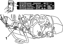
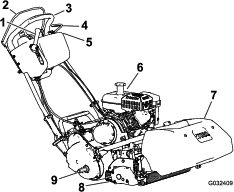
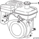
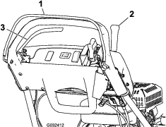
Whenever you need service, genuine Toro parts, or additional information, contact an authorized Toro distributor and have the model and serial numbers of your product ready. Figure 1 identifies the location of the model and serial numbers on the product. Write the numbers in the space provided.
Important: With your mobile device, you can scan the QR code (if equipped) on the serial number decal to access warranty, parts, and other product information.
This manual identifies potential hazards and has safety messages identified by the safety-alert symbol (Figure 2), which signals a hazard that may cause serious injury or death if you do not follow the recommended precautions.

This manual uses 2 words to highlight information. Important calls attention to special mechanical information and Note emphasizes general information worthy of special attention.
Operating this machine between 1,500 and 2,400 m (5,000 to 8,000 ft) above sea level requires the high-altitude kit. See your authorized Toro distributor.
This product complies with all relevant European directives; for details, please see the separate product specific Declaration of Conformity (DOC) sheet.
Warning
CALIFORNIA
Proposition 65 Warning
The engine exhaust from this product contains chemicals known to the State of California to cause cancer, birth defects, or other reproductive harm.
It is a violation of California Public Resource Code Section 4442 or 4443 to use or operate the engine on any forest-covered, brush-covered, or grass-covered land unless the engine is equipped with a spark arrester, as defined in Section 4442, maintained in effective working order or the engine is constructed, equipped, and maintained for the prevention of fire.
Safety
This machine has been designed in accordance with EN ISO 5395:2013 and ANSI B71.4-2017.
General Safety
This product is capable of amputating hands and feet and of throwing objects. Always follow all safety instructions to avoid serious personal injury.
Using this product for purposes other than its intended use could prove dangerous to you and bystanders.
-
Read and understand the contents of this Operator’s Manual before starting the engine.
-
Do not put your hands or feet near moving components of the machine.
-
Do not operate the machine without all guards and other safety protective devices in place and working on the machine.
-
Keep clear of any discharge opening. Keep bystanders a safe distance away from the machine.
-
Keep children out of the operating area. Never allow children to operate the machine.
-
Stop the machine and shut off the engine before servicing, fueling, or unclogging the machine.
Improperly using or maintaining this machine can result in injury. To reduce the potential for injury, comply with these safety instructions and always pay attention to the safety-alert symbol, which means Caution, Warning, or Danger—personal safety instruction. Failure to comply with these instructions may result in personal injury or death.
You can find additional safety information where needed throughout this manual.
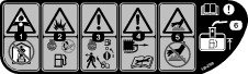
Safety and Instructional Decals
 |
Safety decals and instructions are easily visible to the operator and are located near any area of potential danger. Replace any decal that is damaged or missing. |


Setup
Note: Determine the left and right sides of the machine from the normal operating position.
Preparing the Traction Unit
Optional—Cutting Unit Models 04251, 02452, 04253,
or 04254
If you are installing cutting unit Models 04251, 02452, 04253, or 04254 on this traction unit, complete the following steps:
Installing the Cutting Unit to the Traction Unit
Parts needed for this procedure:
| Bolt (3/8 x 3/4 inch) | 2 |
Note: To install the weight rod onto your machine, refer to the installation instructions in your cutting unit Operator’s Manual.
-
Place the mower on its drums on a level surface.
-
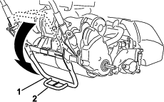
Lower the kickstand and push in the locking pin to lock the kickstand in the SERVICE position (Figure 5). Allow the machine to rest on the locked kickstand.
Note: Place the kickstand in the SERVICE position whenever you remove the cutting unit. This kickstand position keeps the machine from tipping backward onto the handle.
-
Push the cutting unit under the traction unit and to the left to engage the transmission coupling (Figure 6).
-
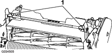
Maneuver the machine frame forward until it engages the cutting unit pivot arms Figure 7.
-
Secure the machine frame to the cutting unit pivot arms with the 2 bolts (3/8 x 3/4 inch) (Figure 7).
-
Move the kickstand to the STORAGE position by releasing the locking pin and allowing the kickstand to rotate up.
-
Set the cutting-unit height of cut; refer to your cutting unit Operator’s Manual.
Installing the Handle Retainers
Parts needed for this procedure:
| Handle retainer | 2 |
| Hairpin cotter | 2 |
-
While supporting the handle, remove the cable ties that secure the handle clamps to the side plates (Figure 8).
-
Pivot the handle to the desired operating position and insert a handle retainer over the handle clamp and into the matching holes in the side plate (Figure 8).
-
Secure the clamp in position with a hairpin cotter (Figure 8).
-
Repeat the procedure on the opposite side of the handle.
-
Adjust the handle height to the desired position; refer to Adjusting the Handle Height.
Note: The machine is shipped with the handle adjusted to the lowest position. The machine is traditionally operated with the handle telescoped out to its maximum height.
Installing the Transport Wheels
Optional
Parts needed for this procedure:
| Transport wheels—Transport Wheel Kit (Model No. 04123 [Optional]) | 2 |
-
Use your foot to push the center of the kickstand down and pull up on the lower handle support until the kickstand has rotated forward and over center (Figure 9).
-
Press the wheel locking clip toward the center of wheel and slide the wheel onto the hex shaft (Figure 10).
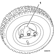
-
Rotate the wheel back and forth until it fits onto the axle and the locking clip is secured in the groove on the axle shaft.
-
Repeat the procedure on the opposite side of the machine.
-
Inflate the tires to 83 to 103 kPa (12 to 15 psi).
-
Carefully lower the machine off of the kickstand by pushing forward slowly or by lifting the lower handle support, allowing the kickstand to spring back to the STORAGE position.
Checking the Engine-Oil Level
Check the engine-oil level; refer to Checking the Engine-Oil Level.
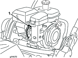
Installing the Production-Year Decal
CE Machines Only
Parts needed for this procedure:
| Production-year decal | 1 |
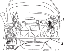
If you use this machine in a country that complies to CE standards, apply the production-year decal near the serial plate; refer to Figure 11.
Installing the Grass Basket
Parts needed for this procedure:
| Grass basket | 1 |
-
Grasp the basket by the handle.
-
Guide the basket lip between the cutting unit side plates and over the front roller (Figure 12).
-
Install the basket hooks over the frame loop (Figure 12).
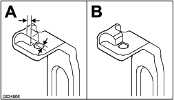
Important: If you ever drop the basket, examine the pitch-arm contact points near the lower lip of the basket for damage (Figure 13). Straighten them before using the basket.Using the basket with bent pitch-arm contact points may cause contact between the basket and cutting unit, causing undesired noise and/or damage to the basket and cutting unit.
Breaking in the Machine
Only 8 hours of mowing operation is required for the break-in period.
The first several hours of operation are critical to future dependability of the machine. You must monitor the machine performance closely so that minor difficulties, which could lead to major problems, are noted and can be corrected. During the first few hours of operation, inspect the machine frequently for signs of oil leakage, loose fasteners, or any other malfunction.
Refer to the engine Owner’s Manual for the recommended break-in-period oil change and maintenance procedures.
Product Overview
Throttle Control
Traction and Reel-Drive Engagement Lever
The traction and reel-drive engagement lever (Figure 17) is located on the front right side of the control panel.
To transport the machine, the lever has 2 positions: NEUTRAL and FORWARD. Pushing the lever to the traction—FORWARD (transport) position or the traction—FORWARD and reel drive—ENGAGE position engages the traction drive (Figure 17).
Note: To move the lever, you must first engage the operator-presence control.
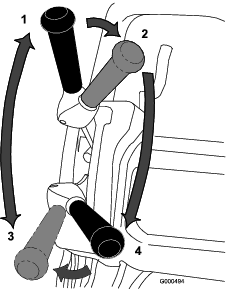
To operate the reel, the lever has 2 positions: ENGAGE and DISENGAGE. Move the top of the lever to the left, then forward to the traction—FORWARD and reel drive—ENGAGE position to engage the reel and begin mowing. Push the lever to the right to the traction—FORWARD (transport) position to disengage the reel and continue forward motion or pull back on it to the traction—NEUTRAL and reel drive—DISENGAGE position to disengage both the reel and the traction drive (Figure 17).
Note: If you release the operator-presence control, the lever returns to neutral and the machine stops.
Service Brake
The service brake (Figure 18) is located on the left front side of the handle. Pulling back the lever applies the service brake.
You must disengage the brake before you engage the traction drive. If you operate the machine with the brake engaged, the machine moves, but with a high resistance and increased power consumption.
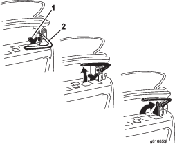
Parking-Brake Latch
Use the parking-brake latch (Figure 18) with the service brake. Rotate the parking-brake latch toward the brake handle to hold the service brake in place. Pull the brake lever to release.
Note: The traction-control lever cannot be moved while the latch is engaged.
On/Off Switch
The On/Off switch (Figure 15) is located on the top of the control panel. Move the switch to the ON position to start the engine and the OFF position to shut off the engine.
Operator-Presence Control (OPC)
You must engage the operator-presence control (Figure 15) before you engage the traction lever. If you release the OPC during operation, the traction lever returns to neutral and the engine continues to run.
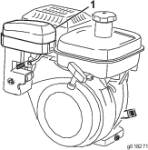
Choke Lever
The choke lever (Figure 19) is located on the left front of the engine. The lever has 2 positions: RUN and CHOKE. Move the lever to the CHOKE position when starting a cold engine. After the engine starts, move the lever to the RUN position.
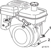
Fuel-Shutoff Valve
The fuel-shutoff valve (Figure 19 and Figure 20) is located on the left front of the engine near the choke lever. The valve has 2 positions: CLOSED and OPEN. Move the lever up to the CLOSED position when you store or transport the machine. Open the valve before you start the engine by rotating the lever down.
Recoil-Starter Handle
Pull the recoil-starter handle (Figure 21) to start the engine.
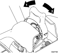
Kickstand
The kickstand (Figure 23) is mounted to the rear of the machine. Use the kickstand when you install or remove the transport wheels or the cutting unit.
-
To use the kickstand to install the transport wheels, lower the kickstand to the ground and step down on the loop while pulling up and back on the lower-center handle (Figure 22).
Caution
The machine is heavy and can cause back strain if lifted improperly.
Put your foot pressure down on the kickstand loop and use only the lower-center handle to raise the machine. Attempting to raise the machine onto the kickstand any other way can cause injury.
-
To prevent the machine from tipping backward when removing the reel, lower the kickstand and push in the locking pin to lock it in the SERVICE position (Figure 24).
| Width | 82.5 cm (32-1/2 inches) |
| Height | 104.8 cm (41-1/4 inches) |
| Length with basket | 152.4 cm (60 inches) |
| Net Weight (with 11-blade cutting unit and grass basket installed) | 117 kg (258 lb) |
| Width of cut | 46 cm (18 inches) |
| Height of cut | 1.5 to 7.5 mm (1/16 to 19/64 inch) with Micro-Cut bedknife |
| Clip frequency | Adjustable (refer to your cutting unit Operator’s Manual) |
| Width | 90.1 cm (35-1/2 inches) |
| Height | 104.8 cm (41-1/4 inches) |
| Length with basket | 152.4 cm (60 inches) |
| Net Weight (with 11-blade cutting unit and grass basket installed) | 117.9 kg (260 lb) |
| Width of cut | 53.3 cm (21 inches) |
| Height of cut | 1.5 to 7.5 mm (1/16 to 19/64 inch) with Micro-Cut bedknife |
| Clip frequency | Adjustable (refer to your cutting unit Operator’s Manual) |
Attachments/Accessories
A selection of Toro approved attachments and accessories is available for use with the machine to enhance and expand its capabilities. Contact your Authorized Service Dealer or Distributor or go to www.Toro.com for a list of all approved attachments and accessories.
To best protect your investment and maintain optimal performance of your Toro equipment, count on Toro genuine parts. When it comes to reliability, Toro delivers replacement parts designed to the exact engineering specification of our equipment. For peace of mind, insist on Toro genuine parts.
Operation
Before Operation
Note: Determine the left and right sides of the machine from the normal operating position.
Before Operation Safety
General Safety
-
Never allow children or untrained people to operate or service the machine. Local regulations may restrict the age of the operator. The owner is responsible for training all operators and mechanics.
-
Become familiar with the safe operation of the equipment, operator controls, and safety signs. Know how to shut off the engine quickly.
-
Check that operator-presence control (if equipped), safety switches, and shields are attached and functioning properly. Do not operate the machine unless they are functioning properly.
-
Inspect the area where you will use the machine, and remove all objects that could interfere with the operation of the machine or that the machine could throw.
-
Evaluate the terrain to determine what accessories and attachments are needed to properly and safely perform the job.
Fuel Safety
-
Use extreme care in handling fuel. It is flammable and its vapors are explosive
-
Extinguish all cigarettes, cigars, pipes, and other sources of ignition.
-
Do not remove the fuel cap or fill the fuel tank while the engine is running or hot.
-
Do not add or drain the fuel in an enclosed space.
-
Do not store the machine or fuel container where there is an open flame, spark, or pilot light, such as on a water heater or other appliance.
-
If you spill fuel, do not attempt to start the engine; avoid creating any source of ignition until the fuel vapors have dissipated.
Performing Daily Maintenance
Perform the daily maintenance procedures; refer to Performing Daily Maintenance.
Checking the Engine-Oil Level
Check the engine-oil level before each use or every 8 operating hours, refer to Checking the Engine-Oil Level.
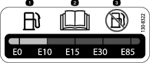
Fuel Specifications
Fuel tank capacity: 3.0 L (0.79 US gallons)
Recommended fuel: Unleaded gasoline with an octane rating of 87 or higher ((R+M)/2 rating method)
Ethanol: Gasoline with up to 10% ethanol (gasohol) or 15% MTBE (methyl tertiary butyl ether) by volume is acceptable. Ethanol and MTBE are not the same. Gasoline with 15% ethanol (E15) by volume is not approved for use.
-
Never use gasoline that contains more than 10% ethanol by volume, such as E15 (contains 15% ethanol), E20 (contains 20% ethanol), or E85 (contains up to 85% ethanol).
-
Do not use gasoline containing methanol.
-
Do not store fuel either in the fuel tank or fuel containers over the winter unless a fuel stabilizer is used.
-
Do not add oil to gasoline.
-
For best results, use only clean, fresh (less than 30 days old) fuel.
-
Using unapproved gasoline may cause performance problems and/or engine damage, which may not be covered under the warranty
Filling the Fuel Tank
Danger
In certain conditions, fuel is extremely flammable and highly explosive. A fire or explosion from fuel can burn you and others and can damage property.
-
Fill the fuel tank outdoors, in an open area, when the engine is cold. Wipe up any fuel that spills.
-
Never fill the fuel tank inside an enclosed trailer.
-
Do not fill the fuel tank completely full. Add fuel to the fuel tank until the level is 6 to 13 mm (1/4 to 1/2 inch) below the bottom of the filler neck. This empty space in the tank allows fuel to expand.
-
Never smoke when handling fuel, and stay away from an open flame or where fuel fumes may be ignited by a spark.
-
Store fuel in an approved container and keep it out of the reach of children. Never buy more than a 30-day supply of fuel.
-
Do not operate without entire exhaust system in place and in proper working condition.
Danger
In certain conditions during fueling, static electricity can be released, causing a spark which can ignite the fuel vapors. A fire or explosion from fuel can burn you and others and can damage property.
-
Always place fuel containers on the ground away from your vehicle before filling.
-
Do not fill fuel containers inside a vehicle or on a truck or trailer bed because interior carpets or plastic truck-bed liners may insulate the container and slow the loss of any static charge.
-
When practical, remove equipment from the truck or trailer and fuel it on the ground. If this is not possible, then fuel such equipment with a portable container rather than from a fuel-dispenser nozzle.
-
If you must use a fuel-dispenser nozzle, keep the nozzle in contact with the rim of the fuel tank or container opening at all times until fueling is complete.
Warning
Fuel is harmful or fatal if swallowed. Long-term exposure to vapors can cause serious injury and illness.
-
Avoid prolonged breathing of vapors.
-
Keep your face away from the nozzle and fuel tank or conditioner bottle opening.
-
Avoid contact with skin; wash off spills with soap and water.
-
Clean around the fuel-tank cap and remove the cap from the tank (Figure 25). Fill the fuel tank no higher than to the bottom of the filter screen.
Important: Do not overfill the tank with fuel.
-
Install the fuel-tank cap and wipe up any spilled fuel.
Setting the Machine to Match Turf Conditions
Use the following table to set the machine to match turf conditions.
| Bedbars: Standard and Optional (Flex/eFlex 2120 Machines) | |||
| Part Number | Description | Aggressiveness | Comments |
| 106-2468-01 | Non-Aggressive | Less | Red, Standard |
| 99-3794-03 | Aggressive | More | Black |
| Bedbars: Standard and Optional (Flex/eFlex 1820 Machines) | |||
| 110-2282-01 | Non-Aggressive | Less | Red, Standard |
| 110-2281-03 | Aggressive | More | Black |
| Bedknives: Standard and Optional (Flex/eFlex 2120 Machines) | |||
| Part Number | Description | Height-of-cut Range | Comments |
| 115-1880 | Microcut-EdgeMax | 1.6 to 3.2 mm (0.062 to 0.125 inch) | Standard |
| 93-4262 | Microcut | 1.6 to 3.2 mm (0.062 to 0.125 inch) | |
| 108-4303 | Extended Microcut | 1.6 to 3.2 mm (0.062 to 0.125 inch) | Less aggressive |
| 115-1881 | Tournament- EdgeMax | 3.2 to 6.4 mm (0.125 to 0.25 inch) | |
| 93-4263 | Tournament | 3.2 to 6.4 mm (0.125 to 0.25 inch) | |
| 108-4302 | Extended Tournament | 3.2 to 6.4 mm (0.125 to 0.25 inch) | Less aggressive |
| 93-4264 | Low Cut | 6.4 mm (0.25 inch) and up | |
| Bedknives: Standard and Optional (Flex/eFlex 1820 Machines) | |||
| 117-1530 | Microcut-EdgeMax | 1.6 to 3.2 mm (0.062 to 0.125 inch) | Standard |
| 98-7261 | Microcut | 1.6 to 3.2 mm (0.062 to 0.125 inch) | |
| 110-2300 | Extended Microcut | 1.6 to 3.2 mm (0.062 to 0.125 inch) | Less aggressive |
| 98-7260 | Tournament | 3.2 to 6.4 mm (0.125 to 0.25 inch) | |
| 117-1532 | Tournament- EdgeMax | 3.2 to 6.4 mm (0.125 to 0.25 inch) | |
| 110-2301 | Low Cut | 6.4 mm (0.25 inch) and up | |
| Rollers (Flex/eFlex 2120 Machines) | |||
| Part Number | Description | Diameter/Material | Comments |
| 04255 | Narrow Wiehle | 6.4 cm (2.5 inches)/Aluminum | Narrow spaced grooves |
| 04256 | Wide Wiehle | 6.4 cm (2.5 inches)/Aluminum | More penetration, wide spaced grooves |
| 04257 | Full Roller | 6.4 cm (2.5 inches)/Steel | Least penetration |
| 04258 | Narrow Wiehle—Long | 6.4 cm (2.5 inches)/Aluminum | More edge support; 4.3 cm (1.7 inches) longer |
| 04267 | Paspalum | 6.4 cm (2.5 inches)/Aluminum | Less penetration, softened narrow spaced grooves |
| 115-7356 | Rear Roller | 5.1 cm (2.0 inches)/Aluminum | Standard rear |
| 120-9595 | Rear Roller | 5.1 cm (2.0 inches)/Steel | Steel rear |
| Rollers (Flex/eFlex 1820 Machines) | |||
| 120-9607 | Narrow Wiehle | 6.4 cm (2.5 inches)/Aluminum | Narrow spaced grooves |
| 120-9609 | Wide Wiehle | 6.4 cm (2.5 inches)/Aluminum | More penetration, wide spaced grooves |
| 120-9611 | Full Roller | 6.4 cm (2.5 inches)/Steel | Least penetration |
| 121-4681 | Narrow Wiehle—Long | 6.4 cm (2.5 inches)/Aluminum | More edge support; 4.3 cm (1.7 inches) longer |
| 120-9605 | Rear Roller | 5.1 cm (2.0 inches)/Aluminum | Standard rear |
Adjusting the Handle Height
Note: The machine is shipped with the handle adjusted to the lowest position. The machine is normally operated with the handle telescoped out to its maximum height.
-
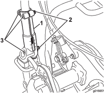
Loosen the 3 carriage bolts and nuts securing each side of the handle in the handle clamps (Figure 26).
-
Pull up on the handle slowly and evenly on each side until it is in the desired operating position.
-
Tighten the carriage bolts and nuts to lock the adjustment.
Adjusting the Handle Angle
Adjusting the Throttle Control
-
Remove the console cover.
-
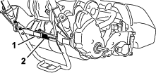
Loosen the 2 fasteners securing the throttle control (Figure 28).
-
Adjust the throttle control to the desired position.
-
Tighten the throttle-control fasteners.
-
Install the previously removed console cover.
Checking the Operation of the Interlock Switches
Caution
If the safety interlock switches are disconnected or damaged, the machine could operate unexpectedly, causing personal injury.
-
Do not tamper with the interlock switches.
-
Check the operation of the interlock switches daily and replace any damaged switches before operating the machine.
Checking the Operator-Presence-Control (OPC) Interlock Switch
-
Push the kickstand down with your foot and pull up on the handle support until the kickstand has rotated forward, over center.
-
Start the engine.
-
With the OPC released, attempt to engage the traction lever (Figure 29). The traction lever should not engage. If the traction lever engages, the interlock system needs service. Correct the problem before operating the machine; refer to Servicing the Traction-Interlock Switch .
-
With the OPC pressed and the traction lever engaged, release the OPC (Figure 29). The traction lever should disengage. If the traction lever does not disengage, the interlock system needs service. Correct the problem before operating the machine; refer to Servicing the Traction-Interlock Switch .
-
With the OPC pressed and the shift lever moved to the left, engage the traction and reel drive and release the OPC (Figure 29). The traction lever should disengage. If the traction lever does not disengage, the interlock system needs service. Correct the problem before operating the machine; refer to Servicing the Traction-Interlock Switch or Adjusting the Reel Control.
-
With the OPC pressed and the shift lever moved to the left to engage the traction and reel drive, move the shift lever to the right to disengage the reel drive (Figure 29). The reel drive should disengage. If the reel drive does not disengage, the interlock system needs service. Correct the problem before operating the machine; refer to Adjusting the Reel Control.
-
Carefully lower the machine off the kickstand.
Checking the Traction-Interlock Switch
-
Push the kickstand down with your foot and pull up on the handle support until the kickstand has rotated forward, over center.
-
With the OPC pressed, the traction lever engaged, and the engine controls in the starting position (Figure 29), attempt to start the engine. The engine should not start. If the engine starts, the interlock switch needs service. Correct the problem before operating the machine; refer to Servicing the Traction-Interlock Switch .
-
Carefully lower the machine off the kickstand.
Checking the Brake-Interlock Switch
-
Push the kickstand down with your foot and pull up on the handle support until the kickstand has rotated forward, over center.
-
With the traction lever disengaged, the service brake engaged, and the engine controls in the starting position (Figure 29), attempt to start the engine. The engine should start. If the engine does not start, the interlock switch needs service. Correct the problem before operating the machine; refer to Servicing the Brake-Interlock Switch.
-
With the engine running, engage the service brake (not the parking-brake latch), press the OPC, and engage the traction lever (Figure 29). The engine should labor to overcome the brake but should not shut off. If the engine shuts off immediately, the interlock switch needs service. Correct the problem before operating the machine; refer to Checking the Brake-Interlock Switch.
-
With the engine running, engage the parking-brake latch, press the OPC, and engage the traction lever (Figure 29). The engine should shut off. If the engine does not shut off, the interlock switch needs service. Correct the problem before operating the machine; refer to Servicing the Brake-Interlock Switch.
-
Carefully lower the machine off the kickstand.
Transporting the Machine to a Job Site
Transporting the Machine Using Transport Wheels
Use the transport wheels to transport the machine a shorter distance.
-
Install the transport wheels; refer to Installing the Transport Wheels
-
Ensure that the traction and reel-drive controls are in the NEUTRAL position.
-
Start the engine; refer to Starting the Engine
-
Set the throttle control to SLOW, tip the front of the machine up, gradually engage the traction drive, and slowly increase the engine speed.
-
Adjust the throttle to operate the mower at the desired ground speed and transport the machine to the desired destination.
Transporting the Machine Using a Trailer
Use a trailer to transport the machine a considerable distance. Use caution while loading and unloading the machine onto the trailer.
-
Carefully drive the machine onto the trailer.
-
Shut off the engine and engage the parking brake.
-
Securely fasten the machine to the trailer.
Note: The Toro Trans Pro trailer can be used to transport the machine. For instructions on loading the trailer, refer to your trailer Operator’s Manual.
Important: Do not run the engine while transporting it on a trailer because damage can occur to the machine.
Hauling the Machine
-
Use care when loading or unloading the machine into a trailer or a truck.
-
Use a full-width ramp for loading the machine into a trailer or truck.
-
Tie the machine down securely.
During Operation
During Operation Safety
General Safety
-
The owner/operator can prevent and is responsible for accidents that may cause personal injury or property damage.
-
Wear appropriate clothing, including eye protection; long pants; slip-resistant, substantial footwear; and hearing protection. Tie back long hair, secure loose clothing, and do not wear loose jewelry.
-
Do not operate the machine while ill, tired, or under the influence of alcohol or drugs. Keep bystanders, especially small children, out of the operating area. Shut off the engine if anyone enters the area.
-
Do not run an engine in an enclosed area where exhaust gases can collect.
-
Operate the machine only in good visibility and appropriate weather conditions. Do not operate the machine when there is the risk of lightning.
-
Before you start the engine, disengage all blade-attachment clutches, shift into neutral, and engage the parking brake.
-
Watch for holes, ruts, bumps, rocks, or other hidden objects. Uneven terrain could cause a slip-and-fall accident.
-
Use extreme care when approaching blind corners, shrubs, trees, or other objects that may block your view.
-
Always stand in the operating position (behind the handle) when starting and operating the machine.
-
Ensure that the grass basket is in place while mowing. Shut off the engine before emptying the basket.
-
Never leave a running machine unattended.
-
Do not touch the engine, muffler, or exhaust pipe while the engine is running or soon after it has shut off because these areas could be hot enough to cause burns.
-
Shut off the engine and disengage the drive to the cutting unit in the following situations:
-
Before fueling
-
Before clearing blockages
-
Before removing the grass basket
-
Before checking, cleaning, or maintaining the cutting unit
-
After striking a foreign object or if an abnormal vibration occurs. Inspect the cutting unit for damage and make repairs before starting and operating the machine
-
Before leaving the operating position
-
-
Disengage the drive to the cutting unit when transporting or not using the machine.
-
Watch out for traffic when crossing or near roadways.
-
Stop the blades whenever you are not mowing.
-
Do not change the engine governor settings or overspeed the engine. Operating the engine at excessive speed may increase the hazard of personal injury.
-
Use accessories and attachments approved by The Toro® Company only.
Slope Safety
-
Slopes are a major factor related to loss of control and rollover accidents, which can result in severe injury or death. The operator is responsible for safe slope operation. Operating the machine on any slope requires extra caution.
-
Evaluate the site conditions to determine if the slope is safe for machine operation including surveying the site. Always use common sense and good judgment when performing this survey.
-
Review the slope instructions, listed below, for operating the machine on slopes and review the conditions in which the machine is being operated to determine whether the machine can be operated in the conditions on that day and at that site. Changes in the terrain can result in a change in slope operation for the machine.
-
Avoid starting, stopping, or turning the machine on slopes. Avoid making sudden changes in speed or direction. Make turns slowly and gradually.
-
Do not operate a machine under any conditions where traction, steering, or stability is in question.
-
Remove or mark obstructions such as ditches, holes, ruts, bumps, rocks, or other hidden hazards. Tall grass can hide obstructions. Uneven terrain could overturn the machine.
-
Be aware that operating the machine on wet grass, across slopes, or downhill may cause the machine to lose traction. Loss of traction may result in sliding and a loss of braking and steering.
-
Use extreme caution when operating the machine near dropoffs, ditches, embankments, water hazards, or other hazards. The machine could suddenly roll over if part of the traction goes over the edge or the edge caves in. Establish a safety area between the machine and any hazard.
-
Identify hazards at the base of the slope.
-
Starting the Engine
Note: For illustrations and descriptions of the controls referenced in this section, refer to Controls.
Note: Ensure that the spark-plug wire is installed on the spark plug.
-
Ensure that the traction and reel drive levers are in the DISENGAGED position.
Note: The engine will not start if the traction lever is in the ENGAGED position.
-
Ensure that the fuel-shutoff valve is open.
-
Move the On/Off switch to the ON position.
-
Move the throttle control to the FAST position.
-
Move the choke lever halfway between the CHOKE and RUN positions when starting a cold engine.
Note: The choke may not be required when starting a warm engine.
-
Pull the recoil-start handle out until positive engagement results, then pull it vigorously to start the engine.
Important: Do not pull the recoil rope to its limit or let go of the starter handle when the rope is pulled out; the rope may break or the recoil assembly may be damaged.
-
Move the choke lever to the RUN position as the engine warms up.
Shutting Off the Engine
-
Move the traction and reel drive controls to the DISENGAGED position.
-
Move the throttle control to the SLOW position.
-
Move the On/Off switch to the OFF position.
-
Close the fuel-shutoff valve before you store or transport the machine
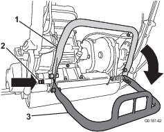
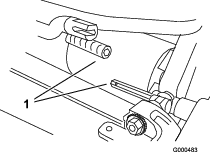
Releasing the Transmission
If the machine becomes disabled, you can disengage the drum from the transmission to allow the machine to be maneuvered.
-
On the right, rear corner of the machine, locate the traction engage/disengage lever next to the drive-housing drum (Figure 30).
-
Carefully rotate the lever rearward to disengage the transmission from the drum.
Caution
The spring-loaded lever may strike your hand if it is not rotated carefully.
Carefully rotate the lever.
-
Move the machine as necessary.
Important: If possible, do not tow the machine. If towing the machine is absolutely necessary, do not tow at any speed greater than 4.8 kph (3 mph); always disengage the transmission from the drum. Failing to do so likely causes damage to the machine.
-
Finish moving the machine, then rotate the lever forward to engage the transmission to the drum.
Note: The service brake is still operational with the transmission disengaged from the drum.
Operating Tips
Important: Grass clippings act as a lubricant when mowing. Operating the cutting unit excessively without grass clippings can damage the cutting unit.
-
Mow the greens in a straight back-and-forth direction across the green.
-
Avoid circular mowing or turning the machine on the greens areas to prevent scuffing.
-
Turn the machine off the green by raising the cutting reel (pushing the handle down) and turning on the traction drum.
-
Mow at a normal walking pace. Fast speeds saves little time and results in an inferior mowing job.
-
To assist in maintaining a straight line across the green and to keep the machine an equal distance from the edge of the previous cut, use the alignment stripes on the basket (Figure 31).
Operating the Machine in Low Light Conditions
Use the LED Light Kit when you operate the machine in low light conditions; contact your authorized Toro distributor.
Important: Do not use other light systems with this machine, as they will not operate properly with the engine AC output.
Operating the Controls while Mowing
-
Start the engine, set the throttle to a reduced speed, push down on the handle to raise the cutting unit, press the operator-presence control, move the traction and reel-drive engagement lever to the FORWARD (transport) position, and transport the machine onto the collar of the green (Figure 32).
-
Move the lever to the NEUTRAL position (Figure 32).
-
Move the lever to the traction—NEUTRAL and reel drive—DISENGAGE position (Figure 32).
-
Move the lever to the traction—FORWARD and reel drive—ENGAGE position (Figure 32), increase the throttle speed until the machine is traveling at the desired ground speed, drive the machine onto the green, lower the cutting unit to the ground, and begin mowing.
Operating the Controls after Mowing
-
Drive off the green, move the reel drive and traction control levers to the DISENGAGED position, and shut off the engine.
-
Empty the grass basket of clippings, install the grass basket on the mower, and transport the machine to storage.
After Operation
After Operation Safety
General Safety
-
Reduce the throttle setting before shutting off the engine and, if the engine has a fuel-shutoff valve, turn off the valve after mowing.
-
Clean grass and debris from the machine to help prevent fires. Clean up oil or fuel spills.
Transporting the Machine
After mowing, transport the machine away from the job site; refer to Transporting the Machine Using Transport Wheels or Transporting the Machine Using a Trailer.
Maintenance
Note: Determine the left and right sides of the machine from the normal operating position.
Important: Do not tip the machine at an angle greater than 25°. Tipping the machine beyond 25° leads to oil leaking into the combustion chamber and/or fuel leaking out of the fuel-tank cap.
Important: When using the machine in conjunction with the Trans Pro 80, always use the stops on the trailer when servicing the machine. Overtipping can result in fuel spills. The stop on the Rail Ramp Kit requires inserting a broom handle or similar item through the holes behind the wheels.
Recommended Maintenance Schedule(s)
| Maintenance Service Interval | Maintenance Procedure |
|---|---|
| After the first 20 hours |
|
| Before each use or daily |
|
| Every 50 hours |
|
| Every 100 hours |
|
| Every 500 hours |
|
| Every 1,000 hours |
|
Important: Refer to your engine Owner’s Manual for additional maintenance procedures.
Pre-Maintenance Procedures
Pre-Maintenance Safety
-
Disengage the drives and the cutting unit, engage the parking brake, shut off the engine, and disconnect the spark-plug wire. Wait for all movement to stop before adjusting, cleaning, or repairing the machine.
-
If the engine must be running to perform a maintenance adjustment, keep your hands, feet, clothing, and any parts of the body away from the cutting unit, attachments, and any moving parts. Keep bystanders away.
-
Keep all parts in good working condition and all hydraulic fittings tight. Replace all worn, damaged, or missing parts and decals. Keep all fasteners tight to ensure that the machine is in safe working condition.
-
Check the grass catcher components frequently and replace them when necessary.
-
Clean grass and debris from the cutting unit, drives, mufflers, cooling screens, and the engine to help prevent fires. Clean up oil or fuel spills.
-
Carefully release pressure from components with stored energy.
-
Replace faulty silencers.
-
If major repairs are ever needed or if assistance is desired, contact an authorized Toro distributor.
-
To ensure optimum performance and continued safety certification of the machine, use only genuine Toro replacement parts and accessories. Replacement parts and accessories made by other manufacturers could be dangerous, and such use could void the product warranty.
Engine Maintenance
Engine Safety
-
Fuel is flammable and explosive, and can cause personal injury.
-
Check all fuel lines for tightness and wear regularly. Tighten or repair them as needed.
-
Tipping the machine may cause the fuel to leak. Do not tip the machine at an angle greater than 25°. If fuel comes in contact with the fuel cap, replace the cap.
-
Run the engine dry or remove the fuel with a hand pump; never siphon the fuel. If you must drain the fuel tank, do it outdoors.
Servicing the Engine Oil
| Maintenance Service Interval | Maintenance Procedure |
|---|---|
| After the first 20 hours |
|
| Before each use or daily |
|
| Every 50 hours |
|
Fill the crankcase with approximately 0.6 L (20 fl oz) of the proper viscosity oil before starting. The engine uses a high-quality oil that has the American Petroleum Institute (API) service classification of SE or higher. Select the proper oil viscosity (weight) based on the ambient temperature. Figure 33 illustrates the temperature/viscosity recommendations.
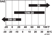
Note: Multi-grade oils (5W-20, 10W-30 and 10W-40) increase oil consumption. Check the engine-oil level more frequently when you use these oils.
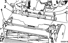
Checking the Engine-Oil Level
| Maintenance Service Interval | Maintenance Procedure |
|---|---|
| Before each use or daily |
|
The ideal time to check the engine-oil level is when the engine is cool or before you have started the engine for the day. If you have already ran the engine, allow the oil to drain back down to the sump for at least 10 minutes before you check the engine-oil level.
-
Remove the transport wheels (if installed).
-
Position the machine so that the engine is level, and clean the area around the oil-level gauge (Figure 34).
-
Remove the oil-level dipstick by rotating it counterclockwise (Figure 34).
-
Wipe the dipstick and insert it into the filler port, but do not screw the dipstick into the port.
-
Remove the dipstick and check the level of the oil.
-
If the level is low, add only enough oil to raise the level until it is between the “H” and “L” marks on the dipstick (Figure 35). Check the level of the oil.
Important: Do not overfill the crankcase.

-
Install the dipstick and wipe up any oil that may have spilled.
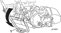
Changing the Engine Oil
| Maintenance Service Interval | Maintenance Procedure |
|---|---|
| After the first 20 hours |
|
| Every 50 hours |
|
-
Start and run the engine for a few minutes to warm the engine oil.
-
At the rear of the machine, place a drain pan under the drain plug (Figure 34). Loosen the drain plug.
-
Push down on the handle to tip the machine and engine backward, allowing all the oil to run into the drain pan.
Important: Do not tip the machine at an angle greater than 25°. Tipping the machine beyond 25° leads to oil leaking into the combustion chamber and/or fuel leaking out of the fuel-tank cap.
-
Install the drain plug and refill the crankcase with the specified oil.
-
Torque the drain plug to 20 to 23 N∙m (15 to 17 ft-lbs).
-
Wipe up any spilled oil.
-
Dispose of the used oil properly. Recycle as per local codes.
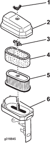
Servicing the Air Cleaner
| Maintenance Service Interval | Maintenance Procedure |
|---|---|
| Every 50 hours |
|
| Every 100 hours |
|
-
Ensure that the wire is off of the spark plug.
-
Remove the wing nut that secures the air-cleaner cover to the air cleaner and remove the cover.
-
Clean the cover (Figure 36 and Figure 37).
-
If the foam element is dirty, remove it from the paper element (Figure 37). Clean it as follows.
-
Wash the foam element in a solution of liquid soap and warm water. Squeeze the element to remove the dirt, but do not twist it, as the foam may tear.
-
Dry the foam element by wrapping it in a clean rag. Squeeze the rag and element to dry it, but do not twist it, as the foam may tear.
-
Saturate the element with clean engine oil. Squeeze the element to remove the excess oil and to distribute the oil.
Note: A foam element that is damp with oil is desirable.
-
-
Check the condition of the paper element. Clean it by gently tapping or replace it as necessary.
Important: Do not use compressed air to clean the paper element.
-
Install the foam element, paper element, and air-cleaner cover.
Important: Do not operate the engine without the air-cleaner element, as extreme wear and damage can likely occur to the engine.
Servicing the Spark Plug
| Maintenance Service Interval | Maintenance Procedure |
|---|---|
| Every 100 hours |
|
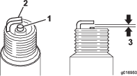
Use an NGK BR6HS spark plug or equivalent. The correct air gap is 0.6 to 0.7 mm (0.024 to 0.028 inch).
-
Pull the molded wire off the spark plug (Figure 38).
-
Clean around the spark plug and remove the plug from the cylinder head.
Important: Replace a cracked, fouled, or dirty spark plug. Do not sand blast, scrape, or clean the electrodes because engine damage could result from grit entering the cylinder.
-
Set the air gap at 0.6 to 0.7 mm (0.024 to 0.028 inch) as shown in Figure 39. Install the correctly gapped spark plug and tighten it firmly to 23 N∙m (17 ft-lb).
Fuel System Maintenance
Cleaning the Fuel-Tank Screen
| Maintenance Service Interval | Maintenance Procedure |
|---|---|
| After the first 20 hours |
|
| Every 100 hours |
|
-
Unscrew and remove the fuel-tank cap from the fuel tank (Figure 40).
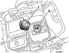
-
Remove the fuel-tank screen from inside the fuel tank.
-
Clean the screen in clean fuel and install it in the tank.
-
Install the fuel-tank cap to the fuel tank.
Replacing the Fuel Line
| Maintenance Service Interval | Maintenance Procedure |
|---|---|
| Every 1,000 hours |
|
If fuel leaks from the fuel line, replace the line immediately.
Replacing the Breather Hose
| Maintenance Service Interval | Maintenance Procedure |
|---|---|
| Every 1,000 hours |
|
If the breather hose is damaged, replace it immediately.
Electrical System Maintenance
Servicing the Traction-Interlock Switch
Use the following procedure if the traction-interlock switch needs adjustment or replacement.
-
Ensure that the engine is off.
-
Remove the control panel.
-
Engage the traction lever.
-
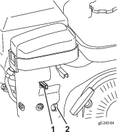
Loosen the interlock switch mounting fasteners (Figure 41).
-
Place a 1.6 mm (0.062 inch) thick shim between the traction lever and the interlock switch (Figure 41).
-
Tighten the interlock switch mounting fasteners.
-
Engage the traction lever and check the gap. The normal operating range is between 0.76 to 3.05 mm (0.03 to 0.12 inch). With the traction lever engaged, verify that the switch loses continuity. Replace the switch if necessary.
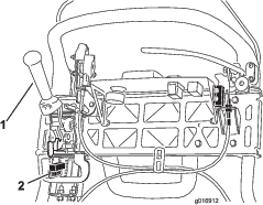
Servicing the Brake-Interlock Switch
-
Ensure that the engine is off.
-
Remove the control panel.
-
Engage the service-brake lever and engage the parking-brake latch.
-
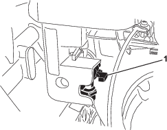
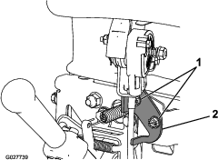
Loosen and remove the interlock-switch mounting fasteners (Figure 42).
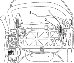
-
Place a 1.6 mm (0.062 inch) thick shim between the parking-brake latch and the interlock switch (Figure 42 ).
-
Install and tighten the interlock switch mounting fasteners. Check the gap. The latch must not contact the switch.
-
Engage the brake lever and rotate the latch. Verify that the switch loses continuity. Replace the switch if necessary.
Brake Maintenance
Adjusting the Service/Parking Brake
If the service/parking brake slips when operated, adjust the cable as follows:
-
Move the service/parking brake lever to the OFF position.
-
Remove the control panel.
-
To increase the cable tension, loosen the upper cable jam nut and tighten the lower cable jam nut (Figure 43) until a force of 156 N (35 lb) applied to the brake-lever handle is required to release the parking-brake latch.
Important: Do not over adjust the brake, as the brake band may drag.
Belt Maintenance
Inspecting the Reel-Drive Belt
| Maintenance Service Interval | Maintenance Procedure |
|---|---|
| Every 1,000 hours |
|
-
Shut off the engine and remove the key.
-
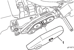
Loosen the flange bolt that secures the belt cover and remove the belt cover to expose the belt (Figure 44).
-
Perform he following steps to adjust the belt tension:
-
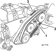
Loosen the bearing-housing mounting nut (Figure 45).
-
Using a 16 mm (5/8 inch) wrench, rotate the bearing housing to ensure that it operates freely.
-
Clean any debris from inside the belt compartment and from around the compression spring (Figure 45).
-
Ensure that the compression spring is applying the proper tension on the belt.
-
Tighten the bearing housing mounting nut.
-
Install the belt cover.
-
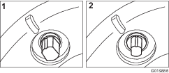
Visually Inspecting the Reel Clutch
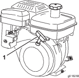
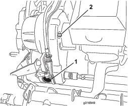
Remove the rubber plug (Figure 46) from the hole in the front of the transmission to visually inspect the reel clutch when making adjustments.
Important: Replace the plug when finished to prevent water and debris from contaminating the clutch.
Engaging/Disengaging the Transmission-Belt Tensioner
The transmission belt is tensioned by a spring-loaded idler pulley. If you must engage or disengage the belt tension, use a 3/8-inch wrench to rotate the engage/disengage shaft (Figure 46) to the desired position. Rotating the shaft 1/4-turn (90°) clockwise disengages the idler from the belt (Figure 47).
Note: You must disengage the belt tension before removing the transmission cover
Note: The transmission belt is properly tensioned when the alignment marks on the transmission cover and the engagement shaft are aligned.
Controls System Maintenance
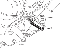
Adjusting the Traction Control
| Maintenance Service Interval | Maintenance Procedure |
|---|---|
| Every 500 hours |
|
If the traction control does not engage or if it slips during operation, an adjustment is necessary.
-
Move the traction control to the ENGAGED position.
-
Measure the distance from the pin on either end of the traction-control spring (Figure 48); if it is not within 7.3 to 7.6 cm (2-7/8 to 3 inches), adjust the clutch according to the steps below.
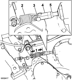
-
Disengage the traction-control lever.
-
Loosen the jam nut on the turnbuckle and remove the clevis pin, disconnecting the spring from the turnbuckle (Figure 48).
-
Turn the turnbuckle in or out to adjust the length as necessary.
-
Install the turnbuckle to the spring with the clevis pin.
-
Move the traction control to the ENGAGED position.
-
Measure the distance from the pin on either end of the traction-control spring (Figure 48); repeat steps 1 through 6 until it is within 7.3 to 7.6 cm (2-7/8 to 3 inches).
-
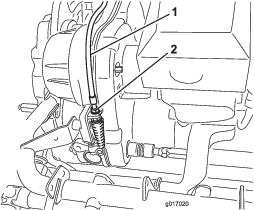
Adjusting the Reel Control
If the reel control does not properly engage, an adjustment is necessary.
-
Ensure that the reel control is disengaged.
-
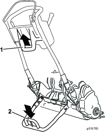
At the transmission bulkhead, adjust the reel-control cable (Figure 49) to attain a spring length of 70.6 to 72.4 mm (2.78 to 2.85 inches).
-
At the control-handle bulkhead, loosen the reel-control cable until there is slack in the cable (Figure 50).
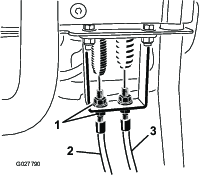
-
At the control-handle bulkhead, tighten the reel-control cable enough to remove the slack from the cable without extending the spring.
-
Check the operation as follows:
-
Verify that the reel-clutch teeth disengage when the clutch is released and the reel-clutch teeth do not bottom out when engaged.
Note: Remove the rubber plug (Figure 46) from the hole in the front of the transmission to view reel clutch.
-
The reel stopping time must be less than 7 seconds with the reel to bedknife backed off.
-
Refer to the Service Manual or contact your authorized Toro distributor for further assistance.
-
Storage
Storage Safety
-
Never store the machine or fuel container where there is an open flame, spark, or pilot light, such as on a water heater or on other appliances.
-
Allow the engine to cool before storing the machine in any enclosure.
Storing the Machine
-
Remove any grass clippings, dirt, and grime from the external parts of the entire machine, especially the engine. Clean the dirt and chaff from the outside of the engine cylinder-head fins and the blower housing.
Important: You can wash the machine with mild detergent and water. Do not pressure-wash the machine. Avoid excessive use of water, especially near the shift-lever plate and the engine.
-
For long-term storage (more than 30 days) add stabilizer/conditioner additive to the fuel in the tank.
-
Run the engine to distribute conditioned fuel through the fuel system (5 minutes).
-
Either shut off the engine, allow it to cool, and drain the fuel tank, or operate the engine until it shuts off.
-
Start the engine and run it until it shuts off. Start the engine again, with the choke closed, until the engine will not start.
-
Disconnect the spark-plug wire from the spark plug.
-
Dispose of the fuel properly. Recycle it according to local codes.
Note: Do not store stabilizer/conditioned gasoline over 90 days.
-
-
Check and tighten all bolts, nuts, and screws. Repair or replace any part that is worn or damaged.
-
Paint all scratched or bare metal surfaces. Paint is available from your authorized Toro distributor.
-
Store the machine in a clean, dry garage or storage area. Cover the machine to protect it and keep it clean.