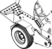


Maintenance
Warning
While you are maintaining or adjusting the machine, someone could start the engine. Accidentally starting the engine could seriously injure you or other bystanders.
Remove the key from the key switch, engage parking brake, and pull the wire(s) off the spark plug(s) before you do any maintenance. Also push the wire(s) aside so it does not accidentally contact the spark plug(s).
Warning
The engine can become very hot. Touching a hot engine can cause severe burns.
Allow the engine to cool completely before service or making repairs around the engine area.
Recommended Maintenance Schedule(s)
| Maintenance Service Interval | Maintenance Procedure |
|---|---|
| After the first 5 operating hours |
|
| After the first 100 operating hours |
|
| Before each use or daily |
|
| Every 25 hours |
|
| Every 50 hours |
|
| Every 80 hours |
|
| Every 100 hours |
|
| Every 160 hours |
|
| Every 200 hours |
|
| Every 250 hours |
|
| Every 500 hours |
|
| Monthly |
|
| Yearly |
|
| Yearly or before storage |
|
Pre-Maintenance Procedures
Caution
Raising the machine for service or maintenance relying solely on mechanical or hydraulic jacks could be dangerous. The mechanical or hydraulic jacks may not be enough support or may malfunction allowing the machine to fall, which could cause injury.
Do not rely solely on mechanical or hydraulic jacks for support. Use adequate jack stands or equivalent support.
Preparing for Maintenance
Perform the following before servicing, cleaning, or making any adjustments to the machine.
-
Park the machine on a level surface and engage the parking brake.
-
Shut off the engine, remove the key, and wait for all moving parts to stop.
Lubrication
Lubricating the Chains
Important: Do not lubricate the chains with penetrating oil or solvents. Use an oil or chain lubricant.
-
Shut off the engine, wait for all moving parts to stop, and remove the key. Engage the parking brake.
-
Lift the rear of the machine and support using jack stands or equivalent support.
Caution
Raising the machine for service or maintenance relying solely on mechanical or hydraulic jacks could be dangerous. The mechanical or hydraulic jacks may not be enough support or may malfunction allowing the machine to fall, which could cause injury.
Do not rely solely on mechanical or hydraulic jacks for support. Use adequate jack stands or equivalent support.
-
Start the engine and move throttle control ahead to 1/2 throttle position. Disengage the parking brake.
Warning
The engine must be running and the drive wheels must be turning so that adjustments can be performed. Contact with moving parts or hot surfaces may cause personal injury.
Keep your fingers, hands, and clothing clear of rotating components and hot surfaces.
-
With the engine running, slowly move the motion-control levers forward and lubricate all 4 chains.
-
Check the condition and tension of the chains; refer to Checking the Condition of the Chains.
Lubricating the Grease Fittings
Note: See the chart below for service intervals.
-
Shut off the engine, wait for all moving parts to stop, and remove the key. Engage the parking brake.
-
Lubricate the fittings with NLGI grade No. 2 multi-purpose grease.
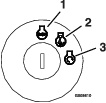
Refer to the following chart for fitting locations and lubrication schedule.
Lubrication Chart Fitting Locations Initial Pumps Number of Places Service Interval 1. Front Wheel Caster Hubs 1 2 Yearly 2. Tine Shaft Bearings 1 4 25 hours 3. Belt Idler Pivot 1 1 Yearly 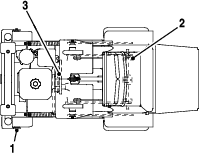
Engine Maintenance
Service Air Cleaner
-
Shut off the engine, engage parking brake, wait for all moving parts to stop, and remove the key.
-
See the engine owner's manual for maintenance instructions.
Servicing the Engine Oil
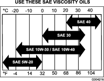
Oil Type: Detergent oil (API service SJ or later)
Engine Oil Capacity: 1.7 L (1.8 US qt) without the filter; 1.5 L (1.6 US qt) with the filter.
Oil viscosity: Refer to the table below.
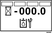
Checking the Engine-Oil Level
Oil Type: Detergent oil (API service SJ or higher)
Oil viscosity: Refer to the table below.
Important: Do not operate the engine with the oil level below the Low (or Add) mark on the dipstick, or over the Full mark.
-
Shut off the engine, engage the parking brake, remove the key, and wait for all moving parts to stop before leaving the operating position.
-
Allow the engine to cool.
-
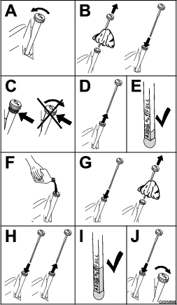
Check the engine-oil level as shown in Figure 30.
-
If the oil level is low, wipe off the area around the oil fill cap, remove cap and add the specified oil until the oil level is at the Full mark on the dipstick.
Note: Do not overfill the engine with oil.
Changing the Engine Oil
Note: Dispose of the used oil at a recycling center.
-
Park the machine so that the drain side is slightly lower than the opposite side to assure the oil drains completely.
-
Shut off the engine, engage the parking brake, remove the key, and wait for all moving parts to stop before leaving the operating position.
-
Change the engine oil as shown in Figure 31.
Note: Torque drain plug to 18 N∙m (13 ft-lb).
-
Slowly pour approximately 80% of the specified oil into the filler tube, and slowly add the additional oil to bring it to the Full mark (Figure 32).
-
Start the engine and drive to a flat area.
-
Check the engine-oil level.
Changing the Engine-Oil Filter
-
Drain the oil from the engine; refer to Changing the Engine Oil.
-
Place a rag under the oil filter to soak up any spilled oil.
Important: Spilled oil may drain under the engine and onto the clutch. Oil spilled on the clutch may damage the clutch, cause the blades to stop slowly when the clutch is in the OFF position, and cause the clutch to slip when the clutch is switched to the ON position. Wipe up any spilled oil.
-
Change the engine-oil filter (Figure 33).
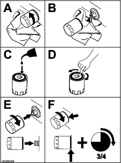
Note: Ensure that the oil-filter gasket touches the engine, and then turn the filter an extra 3/4 turn.
-
Fill the crankcase with the specified type of new oil; refer to Figure 28.
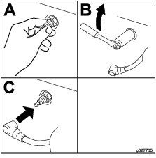
Servicing the Spark Plug
Type for all Engines: NGK BPR6ES or equivalent
Air Gap: 0.75 mm (0.03 inch)
Ensure that the air gap between the center and side electrodes is correct before installing the spark plug.
Use a spark plug wrench for removing and installing the spark plug(s) and a gapping tool/feeler gauge to check and adjust the air gap. Install a new spark plug(s) if necessary.
Removing the Spark Plug
-
Shut off the engine, engage the parking brake, remove the key, and wait for all moving parts to stop before leaving the operating position.
-
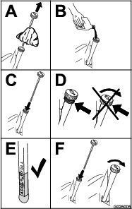
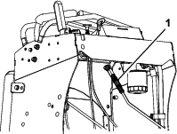
Remove the spark plug as shown in Figure 34.
Checking the Spark Plug
Important: Do not clean the spark plug(s). Always replace the spark plug(s) when it has a black coating, worn electrodes, an oily film, or cracks.
If you see light brown or gray on the insulator, the engine is operating properly. A black coating on the insulator usually means the air cleaner is dirty.
Set the gap to 0.75 mm (0.03 inch).
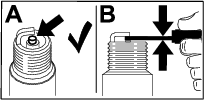
Installing the Spark Plug
Tighten the spark plug(s) to 22 N∙m (16 ft-lb).
Checking the Spark Arrester
Warning
Hot exhaust system components may ignite fuel vapors even after the engine is shut off. Hot particles exhausted during engine operation may ignite flammable materials. Fire may result in personal injury or property damage.
Do not refuel or run engine unless a spark arrester is installed.
-
Shut off the engine, engage the parking brake, remove the key, and wait for all moving parts to stop before leaving the operating position.
-
Allow the muffler to cool.
-
Check the spark arrester for breaks in the screen or welds.
Note: Replace the spark arrester if it is worn or damaged.
-
If you see that the screen is plugged, perform the following:
-
Remove the spark arrester.
-
Shake loose the particles from the arrester and clean screen with a wire brush.
Note: Soak the arrester screen in solvent if necessary.
-
Install spark arrester onto exhaust outlet.
-
Electrical System Maintenance
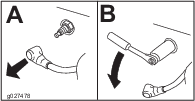
Jump Starting the Machine
-
Check the weak battery for terminal corrosion (white, green, or blue “snow) and clean it prior to jump starting. Clean and tighten connections as necessary.
Caution
Corrosion or loose connections can cause unwanted electrical voltage spikes at anytime during the jump-starting procedure.
Do not attempt to jump start with loose or corroded battery terminals or damage to the engine may occur.
Danger
Jump starting a weak battery that is cracked, frozen, has low electrolyte level, or an open/shorted battery cell, can cause an explosion resulting in serious personal injury.
Do not jump start a weak battery if these conditions exist.
-
Ensure that the booster is a good and fully charged lead acid battery at 12.6 V or greater. Use properly sized jumper cables (4 to 6 AWG) with short lengths to reduce voltage drop between systems. Ensure that the cables are color coded or labeled for the correct polarity.
Caution
Connecting the jumper cables incorrectly (wrong polarity) can immediately damage the electrical system.
Be certain of the battery terminal polarity and jumper cable polarity when hooking up the batteries.
Warning
Batteries contain acid and produce explosive gases.
-
Shield your eyes and face from the batteries at all times.
-
Do not lean over the batteries.
Note: Ensure that the vent caps are tight and level. Place a damp cloth, if available, over any vent caps on both batteries. Ensure that the vehicles do not touch and that both electrical systems are off and at the same rated system voltage. These instructions are for negative ground systems only.
-
-
Connect the positive (+) cable to the positive (+) terminal of the discharged battery that is wired to the starter or solenoid as shown in .
-
Connect the other end of the positive cable to the positive terminal of the booster battery.
-
Connect the black negative (–) cable to the other terminal (negative) of the booster battery.
-
Make the final connection on the engine block of the stalled vehicle (not to the negative post) away from the battery. Stand back.
-
Start the vehicle and remove the cables in the reverse order of connection (the engine block (black) connection is the first to disconnect).
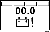
Checking the Battery Charge
Warning
Battery posts, terminals, and related accessories contain lead and lead compounds, chemicals known to the State of California to cause cancer and reproductive harm. Wash hands after handling.
Allowing batteries to stand for an extended period of time without recharging them results in reduced performance and service life. To preserve optimum battery performance and life, charge batteries in storage when the open circuit voltage drops to 12.4 V.
Note: To prevent damage due to freezing, the battery should be fully charged before putting away for winter storage.
Check the voltage of the battery with a digital voltmeter. Locate the voltage reading of the battery in the table and charge the battery for the recommended time interval to bring the charge up to a full charge of 12.6 V or greater.
Important: Ensure that the negative battery cable is disconnected and the battery charger used for charging the battery has an output of 16 V and 7 A or less to avoid damaging the battery (see chart for recommended charger settings).
| Voltage Reading | Percent Charge | Maximum Charger Settings | Charging Interval |
|---|---|---|---|
| 12.6 or greater | 100% | 16 V/7 A | No Charging Required |
| 12.4 – 12.6 | 75 to 100% | 16 V/7 A | 30 Minutes |
| 12.2 – 12.4 | 50 to 75% | 16 V/7 A | 1 Hour |
| 12.0–12.2 | 25 to 50% | 14.4 V/4 A | 2 Hours |
| 11.7–12.0 | 0 to 25% | 14.4 V/4 A | 3 Hours |
| 11.7 or less | 0% | 14.4 V/2 A | 6 Hours or More |
Drive System Maintenance
Caster Pivot Bearings Pre-Load Adjustment
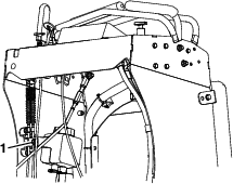
Remove dust cap from caster and tighten nyloc nut until washers are flat and back off 1/4 of a turn to properly set the pre-load on the bearings. If disassembled, ensure that the spring disc washers are installed as shown in Figure 38.
Checking the Air Pressure in the Tires
Note: The semi-pneumatic caster tires do not need to be inflated.
-
Shut off the engine, engage the parking brake, remove the key, and wait for all moving parts to stop before leaving the operating position.
-
Check the pressure of the drive tires.
-
Inflate the drive tires to 152 to 165 kPa (22 to 24 psi).
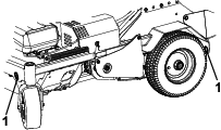
Checking the Wheel Hub Bolts
Torque the wheel hub bolts (Figure 39) to 37 to 45 N∙m (27 to 33 ft-lb).
Note: Do not use anti-seize compound on the wheel hub.
Checking the Torque of the Wheel Lug Nuts
Torque the wheel lug nuts (Figure 39) to 115 to 142 N∙m (85 to 105 ft-lb).
Checking the Condition of the Chains
-
Shut off the engine, engage the parking brake, wait for all moving parts to stop, and remove the key.
-
Check the chains on both sides of the machine for proper tension. The chains should be able to move up and down 1/4 to 1/2 inch (6 to 12 mm).
-
If chains pop or snap refer to Adjusting the Drive Wheel Chain Tension and Adjusting the Tine Drive Chain.
Checking the Sprocket Condition
-
Shut off the engine, engage the parking brake, wait for all moving parts to stop, and remove the key.
-
Inspect sprockets for wear and replace as required.
Maintaining the Chain
Adjusting the Drive Wheel Chain Tension
-
Shut off the engine, engage the parking brake, wait for all moving parts to stop, and remove the key.
-
Lift the rear of the machine and support using jack stands or equivalent support.
-
Check the chains on each side of the idler sprocket, on both sides of the machine, for proper tension. The chains should be able to move up and down 1/4 to 1/2 inch (6 to 12 mm).
-
To adjust the chain tension, loosen the idler bolt and push up on the sprocket to tighten the chain.
Important: Do not overtighten the chain. Significant chain wear can occur and will shorten the life of an overtightened chain.
-
Check the chain tension and tighten the idler bolt.
Checking the Torque of the Transmission Output Shaft Nut
Torque the nuts on the transmission output tapered shafts to 285 to 353 N∙m (210 to 260 ft-lb).
Adjusting the Motion Control Linkage
-
Refer to Preparing for Maintenance.
-
Push the control levers all the way forward to the front reference bar; If either of the control levers contact the reference bar do the following:
-
Allow the control levers to return to neutral and loosen the 2 jam nuts on the hex adjustment linkage.
Note: One jam nut is a right-hand thread and the other is left-hand.
-
Turn the hex adjustment linkage until there is 1/8 to 1/4 inch (3 to 6 mm) gap between the control lever and the front reference bar.
-
Tighten the jam nuts.
-
Proceed with step 3.
-
-
Allow the control levers to return to neutral. Turn the left hex adjustment link until the motion control levers are approximately even with each other.
-
Repeat steps 2 and 3 for the other motion control linkage.
Adjusting the Motion Control Tracking
If the machine travels or pulls to one side when the motion control levers are in the full forward position, adjust the tracking.
-
Push both control levers forward the same distance.
-
Check if the machine pulls to one side; If it does, stop the machine and set the parking brake.
-
Loosen the lock nuts on the right motion control linkage (as viewed from the rear of the machine. Push the right control lever forward and rotate the adjustment rod until there is 1/8 to 1/4 inch (3 to 6 mm) gap between the right control lever and the front reference bar.
-
Place the front reference/speed control bar in the maximum forward position; refer to Adjusting the Front Reference/Speed Control Bar.
-
Rotate the adjustment rod on the left side of the machine (Figure 41).
-
Looking down towards the adjustment rod — rotate it counterclockwise, in 1/4 turn increments, to increase speed or clockwise to decrease speed.
-
Drive the machine and check the full forward tracking.
-
Repeat steps 5 through 7 until desired tracking is obtained.
Brake Maintenance
Adjusting the Parking Brake
If the parking brake does not hold securely, an adjustment is required.
-
Refer to Preparing for Maintenance.
-
Check the air pressure in the drive tires. If needed, adjust to the recommended inflation; refer to Checking the Air Pressure in the Tires.
-
Disengage the parking brake.
-
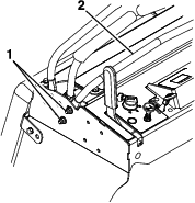
Loosen the cable clamp on the brake cables under the console (Figure 42).
-
Adjust both cable conduits downward approximately 1/8 to 1/4 inch (3 to 6 mm).
-
Tighten the cable clamp and engage the parking brake.
-
Check the parking brake; repeat steps 4 through 6 if necessary.
Belt Maintenance
Checking the Condition and Tension Of Belts
-
Shut off the engine, engage the parking brake, wait for all moving parts to stop, and remove the key.
-
Check the auxiliary pump drive belt condition and tension; the belt should be snug. Refer to Adjusting the Auxiliary Pump Drive Belt.
-
Check the condition of the transmission drive belt.
Adjusting the Auxiliary Pump Drive Belt
-
Shut off the engine, engage the parking brake, wait for all moving parts to stop, and remove the key.
-
To tighten the belt, loosen both nuts (3/8 inch) on the auxiliary pump. Slide the pump outward in slots and tighten the nuts.
-
When properly adjusted, the belt should have 1/2 inch (1.3 cm) of deflection with 3 pounds of force on the belt midway between the auxiliary pump and engine pulley.
Checking the Transmission Drive Belt Tension
Note: No adjustments are required for belt tension.
-
Shut off the engine, engage the parking brake, wait for all moving parts to stop, and remove the key.
-
Install the new belt.
-
Ensure that the idler arm and pulley can move freely.
Hydraulic System Maintenance
Maintaining the Auxiliary Hydraulic System
Hydraulic fluid type: AW-32 hydro fluid
Changing the Auxiliary Hydraulic Reservoir Fluid and Filter
-
Run the machine for approximately 15 minutes to purge any extra air out of the hydraulic system.
-
Completely raise and lower the tines 3 times to purge the air.
-
Shut off the engine, engage the parking brake, wait for all moving parts to stop, and remove the key.
-
Allow the engine to cool.
-
Carefully clean the area around the front of the auxiliary pump and fill cap; also clean around the filter. It is important that no dirt or contamination enter hydraulic system.
-
Unscrew the suction hose from the pump fitting, clean around the pump fitting, and allow oil to drain.
-
Unscrew the filter to remove and allow oil to drain.
Important: Apply a thin coat of oil on the surface of the rubber seal.
Turn the filter clockwise until rubber seal contacts the filter adapter, then tighten the filter an additional 2/3 to 3/4 turn.
-
Install the hose and torque to 37 ft-lb (50 N-m).
-
Remove the cap and check the hydraulic-fluid level in the reservoir.
-
If necessary, add AW-32 hydraulic fluid until the level reaches the FULL COLD line located on the reservoir tank.
Note: If the fluid is at ambient-air temperature, about 24°C (75° F), fill only to the FULL COLD level.
-
Install the hydraulic reservoir cap and tighten it until snug.
Note: Do not overtighten the reservoir cap.
-
Start the engine and raise and lower the tines. Lower the tines to the ground and refill the reservoir to the FULL COLD line.
-
Check the fluid level again; repeat steps 10 through 13 until the level does not decrease.
Maintaining the Transmission
Transmission fluid type: Toro® Hypr-Oil ™ 500 or Mobil® 1 15W-50 synthetic motor oil.
Important: Use the specified fluid. Other fluids could cause system damage.
Checking the Transmission Fluid Level
-
Shut off the engine, engage the parking brake, remove the key, and wait for all moving parts to stop before leaving the operating position.
-
Allow the machine to cool.
-
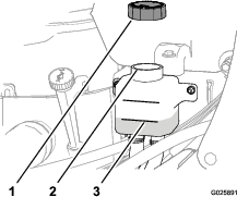
Remove the cap from the expansion tank and check the transmission-fluid level in the tank (Figure 43).
Note: The transmission fluid level should cover the FULL COLD fill line molded into the side of the tank.
-
If necessary, add the specified transmission fluid until the fluid level is at the FULL COLD fill line of the expansion tank (Figure 43).
-
Install the expansion tank cap and tighten it until snug.
Important: Do not overtighten the expansion tank cap.
Changing the Hydraulic Transmission Filters and Fluid
-
Shut off the engine, engage the parking brake, wait for all moving parts to stop, and remove the key.
-
Place a catch pan between the transmissions.
-
Remove the 2 drain plugs, located at the bottom of each transmission, to fully drain the oil.
-
Locate the 2 filters under the transmissions.
-
Carefully clean area around filters. It is important that no dirt or contamination enters the hydraulic system.
-
Remove the filters to and allow the oil to finish draining from the drive system.
Important: Before installing new filters, apply a thin coat of Exmark Premium Hydraulic Fluid on the surface of the filters rubber seal.
Turn the filters clockwise until rubber seal contacts the filter adapter then tighten the filter an additional 3/4 to 1 full turn.
-
Install the 2 drain plugs.
-
Remove the vent plug on each transmission and fill through the expansion reservoir; when oil comes out of the vent install the plug.
Exmark Premium Hydraulic Fluid is recommended. Refer to the chart below for an acceptable alternative:
Hydraulic Fluid Change Interval Exmark Premium Hydraulic Fluid (Preferred) 250 hours Mobil 1 15W50 250 hours Torque the plugs to 20 Nm (180 in-lb). Continue to add Exmark Premium Hydraulic Fluid until it reaches the FULL COLD line on the expansion reservoir.
-
Raise the rear of machine up and support with jack stands (or equivalent support) just high enough to allow the drive wheels to turn freely.
Caution
Raising the machine for service or maintenance relying solely on mechanical or hydraulic jacks could be dangerous. The mechanical or hydraulic jacks may not be enough support or may malfunction allowing the machine to fall, which could cause injury.
Do not rely solely on mechanical or hydraulic jacks for support. Use adequate jack stands or equivalent support.
-
Start the engine and move the throttle control ahead to 1/2 throttle position. Disengage the parking brake.
Warning
The engine must be running and the drive wheels must be turning so motion control adjustment can be performed. Contact with moving parts or hot surfaces may cause personal injury.
Keep your fingers, hands, and clothing clear of rotating components and hot surfaces.
-
With the engine running, slowly move the directional control in both forward and reverse directions (5 to 6 times). Check the oil level, and add oil as required after shutting off the engine.
-
It may be necessary to repeat step 1. until all the air is completely purged from the system. When the transaxle operates at normal noise levels and moves smoothly forward and reverse at normal speeds, then the transaxle is considered purged.
-
Important: Do not change the hydraulic fluid (except for what can be drained when changing filter and removing the drain plugs), unless it is felt the oil has been contaminated or been extremely hot.Changing the oil unnecessarily could damage hydraulic system by introducing contaminants into the system.
Checking the Tines
-
Shut off the engine, engage the parking brake, remove the key, and wait for all moving parts to stop before leaving the operating position.
-
Raise the machine and support it with jack stands with a 460 kg (1,015 lb) capacity.
Caution
Raising the machine for service or maintenance relying solely on mechanical or hydraulic jacks could be dangerous. The mechanical or hydraulic jacks may not be enough support or may malfunction allowing the machine to fall, which could cause injury.
Do not rely solely on mechanical or hydraulic jacks for support. Use adequate jack stands or equivalent support.
-
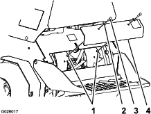
Remove the 2 bolts (3/8 x 1 inch) and 2 washers (3/8 inch) that secure the rear-cover panel to the chassis, and remove the panel (Figure 44).
-
Remove rocks and other debris from the tines.
-
Inspect the tines for wear and damage.
Note: Replace any tines that are worn or damaged.
-
Align the holes in the rear-cover panel to the holes in the chassis (Figure 44).
-
Secure the cover panel to the chassis with the 2 bolts and 2 washers (Figure 44) that you removed in step 3, and torque the bolts to 37 to 45 N∙m (27 to 33 in-lb)
Adjusting the Tine Drive Chain
-
Shut off the engine, engage the parking brake, wait for all moving parts to stop, and remove the key.
-
Lift the rear of the machine and support using jack stands or equivalent support.
-
Check the chains on each side of the idler sprocket, on both sides of the machine, for proper tension. The chains should be able to move up and down 1/4 to 1/2 inch (6 to 12 mm).
-
To adjust the chain tension, loosen the idler bolt and push down on the sprocket to tighten the chain.
Important: Do not overtighten the chain. Significant chain wear can occur and will shorten the life of an overtightened chain.
-
Check the chain tension and tighten the idler bolt.
Adjusting the Return-to-Up Spring
Warning
Springs have stored energy. Overtightening the springs may cause the springs to fail which can cause serious injury or death and damage to the machine and property.
Make sure springs are properly adjusted and/or replaced as specified in the Operator's manual.
Check the gap between the spring bracket and the end of the spring as shown in Figure 45. The gap should measure 1.38 inch (35 mm). The adjustment is made by turning the bolt at the front of each spring (clockwise will shorten the gap, counter-clockwise will lengthen the gap).
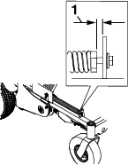
Important: The springs must be replaced it the gap is less than 1.13 inches (29 mm). Always replace both return-to-up springs. This prevents uneven loading and possible damage to the machine.
Cleaning the Engine and the Exhaust System Area
Caution
Excessive debris around engine cooling air intake and exhaust system area can cause engine, exhaust area, and hydraulic system to overheat, which can create a fire hazard.
Clean all debris from engine and exhaust system area.
-
Shut off the engine, engage the parking brake, remove the key, and wait for all moving parts to stop before leaving the operating position.
-
Clean all debris from screen at the top of the engine, around engine shrouding, and exhaust system area.
-
Wipe up any excessive grease or oil around the engine and exhaust system area.
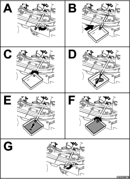
Removing the Engine Shrouds and Cleaning the Cooling Fins
-
Shut off the engine, engage the parking brake, remove the key, and wait for all moving parts to stop before leaving the operating position.
-
Remove cooling shrouds from engine.
-
Clean cooling fins of the engine.
Note: Also clean dust, dirt, and oil from external surfaces of engine, which can cause improper cooling.
-
Install the cooling shrouds into the engine.
Important: Operating the engine without cooling shrouds causes engine damage due to overheating. Do not operate the machine without the cooling shrouds.
Cleaning the Debris from the Machine
-
Shut off the engine, engage the parking brake, remove the key, and wait for all moving parts to stop before leaving the operating position.
-
Clean off any oil, debris, or grass buildup on the machine and aerator deck.
-
Clean off any debris or grass under the chain guards, around the fuel tank, and around the engine and exhaust area.
Disposing of Waste
Disposing of the Engine Oil
Engine oil and hydraulic fluid are both pollutants to the environment. Dispose of used oil at a certified recycling center or according to your state and local regulations.
Disposing of the Battery
Danger
Battery electrolyte contains sulfuric acid, which is poisonous and can cause severe burns. Swallowing electrolyte can be fatal or if it touches skin can cause severe burns.
-
Wear safety glasses to shield eyes, and rubber gloves to protect skin and clothing when handling electrolyte.
-
Do not swallow electrolyte.
-
In the event of an accident, flush with water and call a doctor immediately.
Federal law states that batteries should not be placed in the garbage. Management and disposal practices for batteries must follow relevant federal, state, or local laws.
If a battery is being replaced or if the machine containing the battery is no longer operating and is being scrapped, remove the battery and take it to a local certified recycling center. If no local recycling is available return the battery to any certified battery reseller.