Warning
CALIFORNIA
Proposition 65 Warning
This product contains a chemical or chemicals known to the State of California to cause cancer, birth defects, or reproductive harm.
Setup
Installing the Driveshaft
-
Park the machine on a level surface, shut off the engine, engage the parking brake, lower the cutting units, and remove the key from the ignition switch.
Warning
If you leave the key in the ignition switch, someone could accidently start the engine and seriously injure you or other bystanders.
-
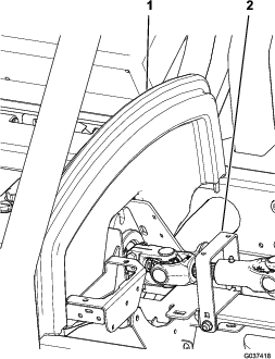
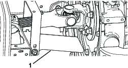
Tip up the seat, open the hood, and remove the hood saddle (Figure 1).
-
Remove the drive-line guard (Figure 1).
Note: Keep the guard and the fasteners for later installation.
-
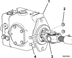
Remove the 2 flange nuts and 2 bolts securing the small end of the existing driveshaft to the hydraulic pump (Figure 2).
Note: Keep the 2 flange nuts and 2 bolts for installing the new driveshaft.
-
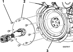
Remove and discard the 8 cap screws securing the large end of the existing driveshaft to the engine flywheel (Figure 3).
-
Remove and discard the existing driveshaft from the machine.
-
Cut and discard the cable tie securing the 2 halves of the new driveshaft together.
-
Grease the slip joint of the new driveshaft.
-
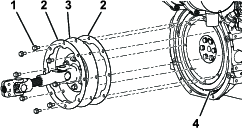
Place a backup ring on each side of the large end of the new driveshaft (Figure 4).
-
Align the holes in the large end of the new driveshaft and the backup rings to the holes in the engine flywheel (Figure 4).
-
Apply medium-strength removable thread-locking compound to the threads of the 8 shorter flange-head cap screws provided (Figure 4).
-
Secure the driveshaft and the backup rings to the flywheel with the 8 flange-head cap screws provided (Figure 4).
Note: Torque the cap screws to 23 to 28 N∙m (17 to 21 ft-lb).
-
Loosely install the existing bolts and flange nuts into the holes in the small end of the driveshaft (Figure 2).
-
Install the small end of the driveshaft onto the shaft of the hydraulic pump and tighten the flange nuts to secure the installation (Figure 2).
Note: Torque the flange nuts to 20 to 25 N∙m (175 to 225 in-lb).
-
Tilt the heat shield down so that the flange-head cap screws do not contact it when the driveshaft rotates (Figure 5).
-
Install the drive-line guard (Figure 1).
-
Install the hood saddle and lower the seat (Figure 1).