Introduction

This cab provides rollover protection (conforming to ISO:21299) and full weather protection. It is supplied complete with a heating and air conditioning system for operator comfort and to de-mist the windscreen and a sound-reduction kit to reduce operator noise levels.

Install the Suppressed Beacon Kit (Part 111-7134) when using this kit if an amber beacon is required.

Read this information carefully to learn how to operate and maintain your product properly and to avoid injury and product damage. You are responsible for operating the product properly and safely.

You may contact Toro directly at www.Toro.com for product safety and operation training materials, accessory information, help finding a dealer, or to register your product.

Whenever you need service, genuine Toro parts, or additional information, contact an Authorized Service Dealer or Toro Customer Service and have the model and serial numbers of your product ready. Figure 1 identifies the location of the model and serial numbers on the product. Write the numbers in the space provided.

g245764

This manual identifies potential hazards and has safety messages identified by the safety-alert symbol (Figure 2), which signals a hazard that may cause serious injury or death if you do not follow the recommended precautions.

g000502

This manual uses 2 words to highlight information. Important calls attention to special mechanical information and Note emphasizes general information worthy of special attention.

This product complies with all relevant European directives. For details, please see the Declaration of Incorporation (DOI) at the back of this publication.

Safety

Warning

If you do not follow certain safety procedures, someone could be seriously injured.

Before working on the machine, the following is essential:

  • You read the machine Operator’s Manual.

  • The engine is switched off and the key is removed.

  • The parking brake is engaged.

  • There is no pressure in the hydraulic system.

  • The cutting units are down on the ground.

Warning

Working on the machine without the appropriate personal protection equipment increases your risk of injury.

When performing maintenance, always use the appropriate personal protection equipment.

Warning

Working on the machine without the safety support bracket increases your risk of injury.

Before carrying out maintenance underneath the operator platform and cab, ensure that the safety support bracket is installed.

Warning

The electrical system of the machine could shock you and cause personal injury.

Before working on the machine electrical systems, always disconnect the battery terminals (negative terminal first) and ensure that no contact is made between the terminals and metal parts of the machine.

Important: Always wear the seat belt when the safety cab is installed.

Important: Refer to your machine Operator’s Manual for advice and guidance when operating a mower on slopes.

To ensure optimum performance and continued safety certification of the machine, use only genuine Toro replacement parts and accessories. Replacement parts and accessories made by other manufacturers could be dangerous, and such use could void the product warranty.

Maximum Slope Angles of Mowers with Cab

You can fit this cab to the mowers listed at the front of this document. When fitted with a cab, each mower model has a different maximum slope angle and this is stated on the decal located on the lid of the storage pod on the left of the machine. Refer to for the correct maximum slope angle decal for your machine when fitted with a cab.

Safety and Instructional Decals

Graphic

Safety decals and instructions are easily visible to the operator and are located near any area of potential danger. Replace any decal that is damaged or missing.

decal978004
decal111-7091
decal111-9832
decal111-9834

Product Overview

g018414
g018399
g018436

Blower Controls

The controls are mounted on the right side in the roof lining.

g025784

Screen Wiper and Washer Switch

The switch is mounted on the left side in the roof lining.

g018467

Interior Light Switch

Press the front of the interior light switch (Figure 8) to turn on the light. Press the rear of the switch to turn off the light.

g020349

Front Window Handle (2)

You can open the front window for ventilation. There are 2 handles (Figure 9).

g018406

Rear Window Handle and Prop

You can open the rear window for ventilation. Rotate the rear window prop to hold the window open (Figure 10).

g020350

Note: Specifications and design are subject to change without notice.

AIR CONDITIONER 
Cooling performance4.2 kW
RefrigerantR134A
Recommended quantity of refrigerant850 g (1.87 lb)
Evaporator—volumetric air flow of the blower660 m3/h (23,307 ft3/h)
ELECTRICAL 
Operating voltage12 V
Fuse for radial blower / compressor15 A
Fuse for axial blower25 A
COMPRESSOR 
DesignationTM-08 HS
Direction of rotation (viewing the pulley)clockwise
Operating speed700 to 6000 rpm
Piston displacement82 cm3/rev (5 inch3/rev)
Pressure-side connection3/4 inch O-ring
Suction-side connection7/8 inch O-ring
Magnetic clutch operating voltage12 V
Magnetic clutch power consumption0.45 W
Refrigerant oilZXL 100 PAG
Refrigerant oil volume in compressor150 cm3 (9.15 inch3)
Refrigerant oil—additional required to fill air-conditioner system25 cm3 (1.53 inch3)
Power consumption of air-conditioner system2.5 kW

Attachments/Accessories

A selection of Toro approved attachments and accessories are available for use with the machine to enhance and expand its capabilities. Contact your Authorized Service Dealer or Distributor or go to www.Toro.com for a list of all approved attachments and accessories.

To ensure optimum performance and continued safety certification of the machine, use only genuine Toro replacement parts and accessories. Replacement parts and accessories made by other manufacturers could be dangerous, and such use could void the product warranty.

Operation

Note: Determine the left and right sides of the machine from the normal operating position.

Operating the Heating System

  1. Set the air conditioner switch to Off.

  2. Set the fan speed switch to the desired speed.

  3. Set the temperature regulator to the required setting.

  4. Rotate and angle the 2 air vents in the roof console to achieve the desired air direction.

Using the Air Conditioner for the First Time

  1. Start the engine.

  2. Switch on the blower switch (Figure 6).

  3. Switch on the air-conditioning switch (Figure 6).

  4. Set the temperature controller (Figure 6) to the maximum Cold setting (full counterclockwise direction).

    Note: After 3 minutes, the air-outlet louvers should emit cold air.

  5. Adjust the fan speed and temperature control to achieve the required amount of cooling.

Operating the Air-Conditioning System

Do not run the air-conditioning system without running the engine as it will not function and the battery will be discharged.

To prevent premature failure of the compressor-shaft seals, run the air-conditioning system for 15 minutes every 14 days.

  1. Set the switch to the ON position.

  2. Set the fan-speed switch to the desired speed.

  3. Set the temperature regulator to the required setting.

    Note: The thermostat in the system switches the compressor on and off to maintain the set temperature.

Operating the Screen Wiper and Washer

  1. Press the right side of the switch to start the screen wipers.

  2. Press and hold the switch to operate the screen washers.

  3. Press the left side of the switch to stop the screen wipers.

Filling the Screen Washer Bottle

Fill the bottle with clean water plus the recommended quantity of propriety windscreen washing fluid (Figure 11).

g020378

Warning

Failure to use washer fluid with antifreeze protection in cold weather could result in impaired windscreen vision and increase the risk of injury or accident.

If you operate your machine in temperatures below 5°C (40°F), use washer fluid with antifreeze protection.

Operating the Windows

Front Window

  1. Rotate the handles counterclockwise and push the window open.

  2. Rotate the handles clockwise to lock the window open.

  3. To close the window, rotate the handles counterclockwise, pull the window closed, and rotate the handles clockwise to lock the window.

Rear Window

  1. Unlock and open the rear window rotating the single handle counterclockwise.

    Note: The gas springs push the window fully open.

  2. Rotate the window prop against the window handle to hold it open.

  3. To close the rear window, rotate the prop away from the window, pull the window closed, and rotate the handle clockwise to lock the window.

Operating the Doors

To open the door from outside the cab, press the door latch handle knob while opening the door (Figure 12).

g020379

To open the door from inside the cab, pull back on the door lock release lever while opening the door (Figure 13).

g020353

Adjusting the Mirrors

While the sitting in the seat, have a helper adjust the side-view mirrors to attain the best view around the side of the machine (Figure 14).

g020380

Maintenance

Note: Determine the left and right sides of the machine from the normal operating position.For all maintenance procedures, park the machine on a level surface, shut off the engine, and remove the key.

Recommended Maintenance Schedule(s)

Maintenance Service IntervalMaintenance Procedure
After the first 100 hours
  • Check all connections for tightness.
  • Every 50 hours
  • Check the refrigerant level.
  • Every 250 hours
  • Check the compressor magnetic clutch for correct operation.
  • Check the water drain for blockage, and clean it as necessary.
  • Examine and clean the condenser fins as necessary.
  • Examine the condition of the electrical cables.
  • Examine the condition and tightness of the electrical connectors.
  • Every 500 hours
  • Check the compressor-fan belt condition and tension, and adjust it as necessary.
  • Examine the hose lines for abrasion and general condition.
  • Check all connections for leaks.
  • Examine the condition of the climatic unit in the cab roof, and check the parts for tightness.
  • Check the compressor brackets tightness of fittings.
  • Every 2 years
  • Change the dryer/filter.
  • Warning

    Working on the machine without the safety support bracket increases your risk of injury.

    Before carrying out maintenance underneath the operator platform and cab, ensure that the safety support bracket is installed.

    Caution

    If you leave the key in the ignition switch, someone could accidently start the engine and seriously injure you or other bystanders.

    Remove the key from the ignition before you do any maintenance.

    Important: Maintenance or repairs on the heating system should be carried out by an Authorized Toro Distributor or a specialist in vehicle heating systems.

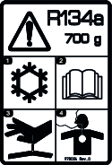
    Important: All work on the refrigerant part of the air-conditioning system should be carried out by fully qualified personnel.

    • You can use the air-conditioning system for many months of the cutting season. Follow the regular prescribed maintenance to prolong the life of the system and ensure efficient operation. Failure to carry out the prescribed and documented maintenance could invalidate the warranty on the system and its components.

    • Even if the air-conditioning system is used infrequently, follow the maintenance schedule, as aging and refrigerant loss can occur with time.

    • Clean the condenser and evaporator fins with compressed air in the opposite direction of the normal air flow. If there is any buildup of greasy deposits, clean it with a non-abrasive soap solution.

    • Low levels of refrigerant can reduce the efficiency of the air-conditioning unit.

    • Extremely low levels can cause the low-pressure switch to shut down the system.

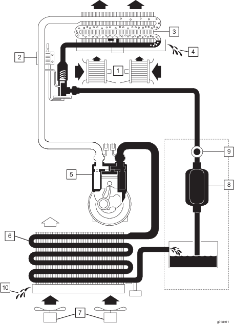
    • To check the refrigerant level, there is an integrated sight glass in the collecting tank. After filling, run the system for 5 minutes to allow all air bubbles to be purged from the system. Check the level after this period and top up is necessary. The occasional air bubble can be accepted.

      Important: Do not spill compressor oil on the vehicle surface. It can cause discoloration of vehicle paint and deterioration of acrylic or ABS plastic components.

    • When attaching the climatic hoses, oil the sealing rings with refrigerator oil.

    • After removal of climatic hoses from the air-conditioner system, always replace the O-rings with new ones specified for refrigerant 134A.

    • When tightening or loosening fittings, always use 2 wrenches to prevent the tubes from twisting.

    Checking the Refrigerant Pressure

    When using the air-conditioning system the operating pressure is different on the suction side and the pressure side of the compressor.

    This pressure difference is influenced by the speed of the compressor, the inside temperature of the vehicle, the outside air temperature and the relative air humidity.

    Pressures that differ from those in the table below indicate a possible fault in the system.

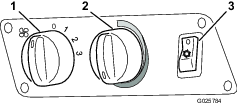
    To check the pressures, set the compressor speed to 2000 rpm with an air temperature between 20 and 40 degrees C (68 and 104 degrees F). Operate the blower at position 3 (fastest speed setting).

    System Refrigerant Pressures

    Outside TemperatureLow-Pressure SideHigh-Pressure Side
    20° C (68° F)1.7 to 2.1 bar (24.7 to 30.5 psi)10 to 14 bar (145 to 203 psi)
    25° C (77° F)1.8 to 2.2 bar (26.1 to 31.9 psi)12 to 16 bar (174 to 232 psi)
    30° C (86° F)1.9 to 2.3 bar (27.6 to 33.4 psi)14 to 18 bar (203 to 261 psi)

    Troubleshooting the Pressure Readings

    During the compression test, deviations from the values in the table may be measured. Locating the cause can determine whether a part requires repair or replacement.

    The following is a short list of some pressure deviation that may be measured and some possible causes.

    • Pressure on high-pressure manometer too high

      • The air volume in the condenser is too small.

      • Refrigerant quantity is too high

      • The dryer/filter is blocked.

    • Pressure on high-pressure manometer is too low

      • The refrigerant quantity is too low (check the sight glass).

      • The compressor speed is too low (check the drive belt for slip/tension).

      • There is a fault with the compressor.

    • Pressure on low-pressure manometer too high

      • The expansion valve is incorrect.

      • The compressor speed is too low (check the drive belt for slip/tension).

      • There is a fault with the compressor.

    • Pressure on low-pressure manometer too low

      • There is restriction in the suction or pressure hoses.

      • The expansion valve is incorrect.

      • The refrigerant quantity is too low (examine the sediment bowl).

      • The air volume in the evaporator is too small.

      Have a qualified person examine and repair all deviations in pressure from the values in the table.

    Important: Do not allow refrigerant to discharge into the atmosphere. Before opening or disconnecting parts from the refrigerant circuit, empty the refrigerant into a specified recycling bottle, and dispose of it correctly.

    Always use genuine Toro spare parts when repairing or servicing the air-conditioning system.

    Checking the Refrigerant Level

    Maintenance Service IntervalMaintenance Procedure
    Every 50 hours
  • Check the refrigerant level.
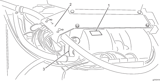
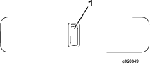
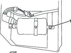
  • Check the refrigerant to assure it is at the correct level for operation. As the level of the refrigerant lowers, more air bubbles can be seen passing through the sight glass. Low levels of refrigerant can reduce the efficiency of the air-conditioning unit. Extremely low levels can cause the low-pressure switch to shut down the system.

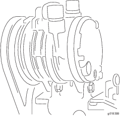
    1. Using the sight gauge in the collecting tank, check on refrigerant level (Figure 15).

      g019080
    2. After filling, run the system for 5 minutes to allow all air bubbles to be purged from the system.

    3. Check the level after this period and top up is necessary.

      Note: The occasional air bubble is acceptable.

    Checking the Compressor Magnetic Clutch

    Maintenance Service IntervalMaintenance Procedure
    Every 250 hours
  • Check the compressor magnetic clutch for correct operation.
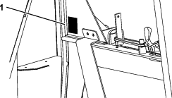
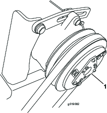
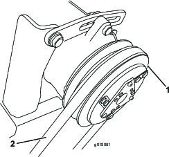
  • The compressor magnetic clutch is operating correctly if it clicks when it is turned on (Figure 16).

    g019082

    Checking the Drain Tube

    Maintenance Service IntervalMaintenance Procedure
    Every 250 hours
  • Check the water drain for blockage, and clean it as necessary.
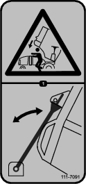
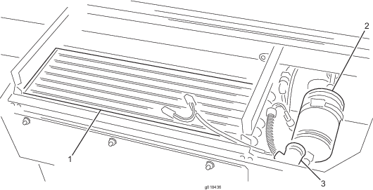
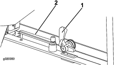
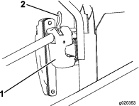
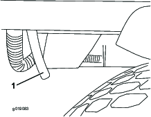
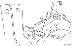
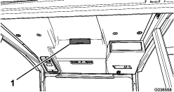
  • The water drain is the clear plastic tube connected to the condenser. It runs from the condenser through the cab structure to below the front of the cab (Figure 17). Check the water drain for blockages and clean as necessary.

    If the tube is blocked, use a flexible unblocking tool (pipe cleaner) or disconnect the tube and blow it out with compressed air.

    g019083

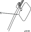
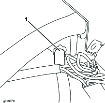
    Note: If the blockage is not reachable with a flexible unblocking tool, the other end of the tube can be disconnected and blown out with compressed air (Figure 18).

    g019079

    Checking the Compressor-Fan Belt

    Maintenance Service IntervalMaintenance Procedure
    Every 500 hours
  • Check the compressor-fan belt condition and tension, and adjust it as necessary.
    1. Proper tension allows 10 mm (3/8 inch) deflection when applying a force of 40 N (9 lb) on the belt, midway between the pulleys.

    2. If the deflection is not 10 mm (3/8 inch), loosen the upper and lower compressor-mounting bolts.

      g019081
    3. Increase or decrease the compressor-belt tension and tighten the bolts.

    4. Check the deflection of the belt again to ensure that the tension is correct.

    Tilting the Cab

    You can tilt the cab for access under the operator platform for cleaning and maintenance.

    The cab and the operator platform tilt together as a single unit. The angle of tilt is less than that of a platform without a cab. This is to ensure that, owing to the weight and position of the tilted cab, the machine has sufficient stability when the cab is tilted.

    Tilting the Cab Upward

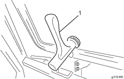
    1. Remove the R-clips and rotate the 2 locking levers, located on the cross beam at the rear of the cab, so that they point upward (Figure 20).

      g018407
    2. Slide the levers inward to remove them from the brackets.

      Note: If the levers are difficult to remove, align the locking pegs with the slots in the bracket and then remove the levers.

    3. On both sides of the cab, on the rear corner post, there is a grab handle for raising the cab from either side. Lift up on 1 of these handles.

      Note: The built-in gas springs assist in raising the cab in a controlled manner and stop it when it is fully raised.

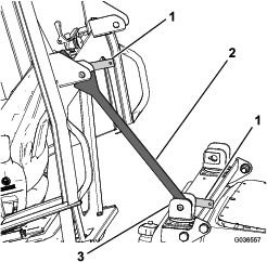
    4. With the cab fully raised, install the safety support bracket as follows:

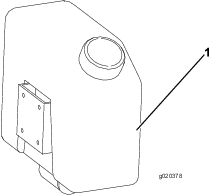
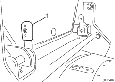
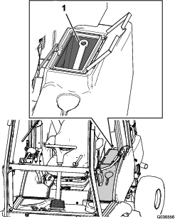
      1. Remove the safety support bracket from the storage pod.

        g036556
      2. Using either of the 2 cross-beam brackets, place the safety support bracket within the cross-beam brackets and insert the appropriate locking lever through both brackets and rotate it downward.

        g036557
      3. Once the safety support bracket is secured, rotated the cross-beam bracket toward the cab so that it rests against the bracket on the rear of the cab (Figure 22).

      4. Insert the remaining locking lever through the top bracket to ensure that the safety support bracket stays in place (Figure 22).

    Lowering the Cab

    1. Remove the safety support bracket as follows:

      1. Remove the 2 locking levers securing the safety support bracket to the cross-beam brackets.

      2. Remove the safety support bracket from the cross-beam bracket.

      3. Place the safety support bracket in the storage pod (Figure 21).

    2. Pull down on 1 of the grab handles to lower the cab so that the brackets on the rear of the cab align between the brackets on the cross beam.

    3. With the levers in the vertical position (Figure 20), push them through the sets of brackets.

      Note: Move the levers back and forth into the brackets to align the locking pegs in the slots.

    4. When the levers are fully inserted, rotate them backward to lock them in position (Figure 23).

      g018408
    5. Install the R-clips.
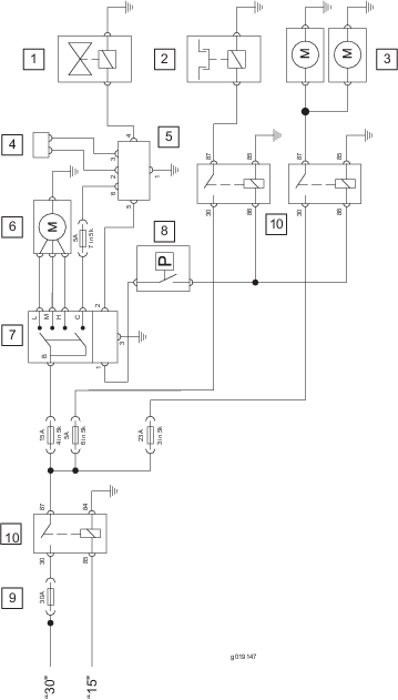
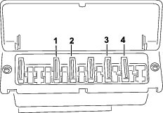
    Locating the Fuses

    The cab fuses are located in the fuse box in the cab headliner (Figure 24).

    g036558
    g245763

    Washing the Machine and Cab

    When washing the machine and the cab, do not direct water into the roof area.

    Storage

    Refer to the traction unit Operator’s Manual for details on storing the machine.

    Schematics

    Functional schematic of the air-conditioning system

    g018401

    Electrical schematic of the air-conditioning system

    g019147