Warning
CALIFORNIA
Proposition 65 Warning
This product contains a chemical or chemicals known to the State of California to cause cancer, birth defects, or reproductive harm.
Determine the left and right sides of the machine from the normal operating position.
-
Park the machine on a level surface, lower the cutting units, shut off the engine, set the parking brake, remove the ignition key, and disconnect the spark plug.
-
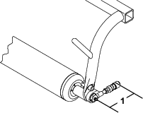
Remove the roller, spring washers, pull link assemblies, flat washers, lockwashers, and grease screws from the pull frame (Figure 1).
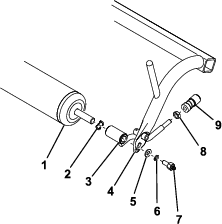
-
Remove and retain the ball joint receivers from the pull link assemblies (Figure 1). Discard all of the previously removed hardware except the roller and ball joint receivers.
-
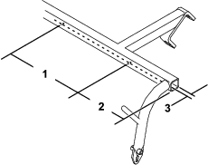
If the pull frame does not have 2 holes in the underside, drill them at the location shown in Figure 2 using a 0.221 inch drill bit.
-
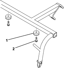
Secure 2 bumpers to the underside of the pull frame using 2 self tapping screws (Figure 3).
-
Slide a frame spacer onto each end of the roller (Figure 4).
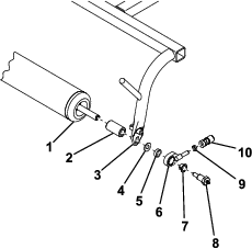
-
Secure the roller to the pull frame as shown in Figure 4.
-
Thread a jam nut and the previously removed ball joint receiver onto the pull link assembly (Figure 4). Do not tighten the jam nut at this time.
-
Adjust the ball joint receiver so that the distance between the grease screw and the opening in the ball joint receiver is 9.1 cm (3.6 inches) and tighten the jam nut to secure it in place (Figure 5).
-
Thread a ball stud onto each end of the groomer front rollers (Figure 6).
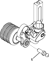
-
Slide the sleeve on the ball joint receivers back and hook them onto the groomer ball studs.