Warning

CALIFORNIA

Proposition 65 Warning

This product contains a chemical or chemicals known to the State of California to cause cancer, birth defects, or reproductive harm.

Important: Read these instructions thoroughly before setting up or operating the groomer. Failure to follow the set up or operating instructions in this manual may result in damage to the machine, groomer, and the turf.

Note: Determine the left and right sides of the machine from the normal operating position.

Setup

Preparing the Machine

  1. Park the machine on a level surface.

  2. Engage the parking brake.

  3. Shut off the engine and remove the key from the switch.

Moving the Front Roller

  1. Loosen the jam nuts and set screws securing each end of the front roller to the height-of-cut arms (Figure 1).

  2. Remove the carriage bolts and locknuts securing the height-of-cut arms to the adjusting brackets (Figure 1).

  3. Remove the height-of-cut arms from the side plates and roller assembly.

    g017178
  4. Remove the height-of-cut hardware as follows:

    • Greensmaster 1600 mowers—remove the height-of-cut adjusting screws, jam nuts, and set screws from the height-of-cut arms (Figure 1).

    • Greensmaster 800 and 1000 mowers—remove the 2 taper-face bolts securing the right and left height-of-cut brackets to the side plates (Figure 1). Install the height-of-cut brackets to the opposite sides of the machine with the 2 taper-face bolts, using the rear sets of mounting holes in the side plates.

  5. Install the height-of-cut arms as follows:

    • Greensmaster 1600 mowers—obtain 2 new height-of-cut arms from your authorized Toro distributor and install them onto the roller assembly and side plates with the fasteners removed previously (Figure 2).

    • Greensmaster 800 and 1000 mowers—rotate the height-of-cut arms you removed previously to the forward position and install them onto the roller assembly and side plates with the fasteners removed previously (Figure 2).

    g017179

Installing the Groomer Housing

Parts needed for this procedure:

Groomer-housing assembly1
Flat-head screw (3/8 x 2 inches)2
Locknut (3/8 inch)2
Bearing adapter1
Spacer2
O-ring1
Synthetic grease-
Slot cover1
Adapter ring1
  1. Remove the 2 bolts and locknuts securing the end cap to the left, reel-bearing housing and the side plate.

  2. Remove and retain the end cap and fasteners for use if you ever remove the groomer (Figure 3).

    g017288
  3. If you are installing this kit on a Greensmaster 800 mower with a serial number prior to 230999999, a Greensmaster 1000 mower with a serial number prior to 229999999, or a Greensmaster 1600 mower with a serial number prior to 260001401, complete the following:

    1. Using a 7/8 inch standard wrench, loosen the spring tension screws on the right and left bedbar adjusters (Figure 4).

      g020979
    2. Back out the screws until the thrust washers are no longer tensioned against the bedbar.

    3. Remove the 2 bolts and washers securing left, bedbar-adjuster frame to the side plate (Figure 4).

  4. Remove the 40-tooth idler gear.

    g022023
  5. Remove the curved washer and the bolt (3/8 x 5/8 inch) from the adjustment-knob mounting block (Figure 6).

    g245796
  6. Install the O-ring into the back of the groomer housing (Figure 6 and Figure 7) and lightly lubricate the exposed surfaces of the O-ring with synthetic grease (supplied with the kit).

    g020843
  7. Insert the adapter ring into the reel bearing housing (Figure 6 and Figure 8).

    g020844
  8. Insert the 2 flat-head screws (3/8 x 2 inch) through the bearing adapter and position the spacers on the ends of the screws (Figure 6 and Figure 8).

  9. Align the bearing adapter, spacers, and screws with the bronze bushing and the slots in the groomer housing.

  10. Slide the bearing adapter through the bronze bushing and the screws through the slots in the groomer housing assembly (Figure 6 and Figure 8).

    Important: Ensure that the bearing adapter is oriented as shown in Figure 9.

    g020854
  11. Place the slot cover over the screws and up against the lubricated O-ring (Figure 6).

  12. Ensure that the flat edge of the slot cover is oriented at the bottom.

  13. Insert the flat-head screws through the reel-bearing housing and secure them with locknuts.

  14. Torque the locknuts to 31 to 37 N∙m (23 to 27 ft-lb) (Figure 6 and Figure 8).

    Note: To gain access to the locknuts you may need to move or remove the bedbar.

  15. Mount the adjustment knob mounting block to the left side plate with the bolt (3/8 x 5/8 inch) and curved washer you removed previously (Figure 6).

  16. If you are installing this kit on a Greensmaster 800 mower with a serial number prior to 230999999, a Greensmaster 1000 mower with a serial number prior to 229999999, or a Greensmaster 1600 mower with a serial number prior to 260001401, install the left, bedbar-adjuster frame to the side plate with the bolts and washers that you removed previously (Figure 4).

Installing the Drive Gear

Parts needed for this procedure:

Shaft assembly1
Drive gear1
Synthetic grease
  1. Remove the reel-bearing locknut from the reel shaft (Figure 10).

    Note: The reel-bearing locknut has right-handed threads.

    g022029
  2. Secure the reel from turning with a wood block.

  3. Thread the shaft assembly onto the reel-shaft extension (Figure 11).

    g022024
  4. Secure the reel from turning with a wood block and torque the shaft assembly to 54 to 81 N∙m (40 to 60 ft-lb).

  5. Apply synthetic grease (supplied with the kit) to the male spline of the shaft assembly (Figure 11).

  6. Slide the drive gear with the groove oriented outward onto the shaft assembly (Figure 11).

  7. Install the 40-tooth idler gear (Figure 11).

Setting the Groomer for Forward Rotation (Optional)

Parts needed for this procedure:

Forward Rotation Kit (obtain separately)1

The groomer comes designed to rotate in the opposite direction of the reel. Optionally, you can set it to rotate in the same direction as the reel by obtaining the Forward Rotation Kit using the following procedure:

  1. Remove the 2 socket-head bolts and locknuts from the cover (Figure 12).

    g020880
  2. Keep one of the bolts and discard the rest of the fasteners.

  3. Remove the center gear assembly, saving the gear and discarding the bushing and bolt (Figure 13).

    g020881
  4. Install the socket-head bolt you removed from the cover into the hole where the center gear was installed (Figure 14).

    g020882
  5. Press fit the center gear removed previously onto the hub (Figure 15).

    Important: Support the inner race of the gear bearing while pressing it onto the hub.

    g020883
  6. Install the center gear and hub assembly and the gear assembly, from the forward rotation kit, to the cover with 2 flange-head bolts as shown in Figure 15.

Installing the Groomer-Housing Cover

Parts needed for this procedure:

Groomer-housing cover assembly1
Gasket1
Flange-head bolt (1/4 x 3/4 inch)5
Synthetic grease (3.0 oz)1
  1. Coat the teeth of the gears with the synthetic grease supplied with the kit. Use the remaining grease to fill in the area around the gears.

  2. Place the gasket over the dowel pins on the groomer housing (Figure 16).

    g020848
  3. Install the cover onto the groomer housing, inserting the actuator pin of the clutch assembly into the groove of the drive gear (Figure 16).

  4. Secure the cover with 5 flange-head bolts (Figure 16) and torque them to 9.6 to 10.5 N∙m (85 to 95 in-lb).

Installing the Groomer on the Right Side of the Machine

Parts needed for this procedure:

Bearing Adapter1
Spacer2
Groomer-plate assembly1
Adapter ring1
Bolt (1/4 x 3-3/4 inches)2
Star washer2
Fastener retainer2
Weight1
  1. Remove the 4 bolts securing the reel-drive-belt cover to the right, side plate and remove the cover (Figure 17).

    g017184
  2. Loosen the idler pulley to relieve the belt tension and remove the reel-drive belt from the pulleys (Figure 18).

    g017185
  3. Using a 1/2 inch drive ratchet and extension, remove the drive pulley from the reel shaft (Figure 18).

    Note: The drive pulley has right-hand threads.

  4. Secure the reel from turning with a wood block.

  5. Remove the 2 flat-head screws and nuts securing the groomer arm cover to the bearing housing and side plate (Figure 18).

  6. Remove the groomer arm cover (Figure 19); retain the flat-head screws and discard the spacers under the cover.

  7. If you are installing this kit on a Greensmaster 800 mower with a serial number prior to 230999999, a Greensmaster 1000 mower with a serial number prior to 229999999, or a Greensmaster 1600 mower with a serial number prior to 260001401, remove the 2 bolts and washers securing the right bedbar adjuster frame to the side plate.

  8. Remove the curved washer and the bolt (3/8 x 5/8 inch) from the adjustment-knob, mounting block (Figure 19).

  9. Insert an adapter ring into the reel-bearing housing (Figure 19).

    g020847
  10. Insert the 2 flat-head screws (3/8 x 2 inch) through the groomer arm cover and the bearing adapter and put a spacer over each screw (Figure 19).

  11. Install the groomer arm cover, bearing adapter, spacers, and groomer-plate assembly to the reel-bearing housing, sliding the adapter through the bronze bushing in the groomer plate assembly and into the reel bearing housing (Figure 19).

  12. Install the locknuts on the flat-head screws and torque them to 31 to 37 N∙m (23 to 27 ft-lb).

  13. Secure the mounting block of the groomer adjustment knob assembly to the right side plate with the bolt (3/8 x 5/8 inch) and curved washer removed previously (Figure 19).

  14. If you are installing this kit on a Greensmaster 800 mower with a serial number prior to 230999999, a Greensmaster 1000 mower with a serial number prior to 229999999, or a Greensmaster 1600 mower with a serial number prior to 260001401, install the right, bedbar-adjuster frame to the side plate with the bolts and washers you removed previously.

  15. Using a 1/2 inch drive ratchet and extension, install the drive pulley (right-hand threads) to the reel shaft (Figure 20).

    g017188
  16. Secure the reel from turning with a wood block.

  17. Torque the pulley to 54 to 81 N∙m (40 to 60 ft-lb).

  18. Install reel drive belt and check the belt tension by pressing the belt at the mid span of the pulleys with 1.5 to 2.5 kg (3 to 5 lb) of force.

    The belt should deflect 6 mm (1/4 inch). Reposition the idler pulley to adjust the belt tension. Tighten the screws once you achieve the proper tension.

  19. Install the reel-drive-belt cover to the side plate as follows:

    • Greensmaster 800 mowers—install the reel drive cover to the side plate with the 4 bolts you removed previously.

    • Greensmaster 1000/1600 mowers—install the cover using the upper and lower bolts removed previously and the weight and new fasteners as shown in Figure 21. Use the fastener retainers as required by your local codes.

      g020853

Installing the Grooming Reel

Parts needed for this procedure:

Shaft clamp4
Bolt (1/4 x 1-1/4 inches)4
Jam nut4
Groomer reel (obtain separately)1
  1. Obtain a groomer reel appropriate for your needs and cutting unit; refer to the following table for a list of groomer reels:

    Model NumberGroomer
    0480118 inch groomer, twin tip
    0480221 inch groomer, twin tip
    0480326 inch groomer, twin tip
    0428018 inch groomer, spring steel
    0428118 inch groomer, carbide
    0428321 inch groomer, spring steel
    0428421 inch groomer, carbide
    0428626 inch groomer, spring steel
    0428726 inch groomer, carbide
    0426818 inch soft grooming brush
    0426918 inch stiff grooming brush
    0427021 inch soft grooming brush
    0427121 inch stiff grooming brush
    0427626 inch stiff grooming brush
  2. Loosely install the 2 halves of a groomer-shaft clamp to the driven shaft on the right side of the machine (Figure 22 and Figure 23).

  3. Slide the groomer-reel shaft into the clamp on the right side and swing it up to the drive shaft on the left (Figure 22).

    Important: If installing a carbide-toothed groomer, ensure that the teeth point in the direction the groomer will rotate when installed.

    g246532
    g240752
  4. Secure the groomer reel with the clamps and nuts as shown in Figure 22 and Figure 23, torquing the socket head screws to 9.6 to 10.5 N∙m (85 to 95 in-lb).

  5. Rotate both quick-up levers to raise the grooming reel into the transport position (Figure 20).

  6. Correct any problems and check the assembly.

  7. Using a hand-pump grease gun, lubricate the 2 groomer-shaft bearings (1 on each end).

    Note: Pump only 2 to 3 pumps maximum to avoid permanently damaging the grease seals.

  8. Center the roller between the height-of-cut arms and tighten the set screws and jam nuts.

Operation

Introduction

Grooming is performed in the turf canopy above the soil level. Grooming promotes vertical growth of grass plants, reduces grain, and severs stolons, producing a denser turf. Grooming produces a more uniform and tighter playing surface for faster and truer action of the golf ball.

Grooming should not be considered as a replacement for verticutting. Verticutting is generally a more rigorous and periodic treatment that can temporarily damage the playing surface, while grooming is a routine and gentler treatment designed to manicure the turf.

g006671

Grooming brushes are less intrusive than conventional grooming blades when adjusted to lightly contact the turf canopy. Brushing may be better for the ultra-dwarf cultivars, since these grass types have an upright growth pattern and do not fill in well through horizontal growth. Brushes can injure leaf tissue if they are set to penetrate too deeply into the canopy.

Groomer blades should never penetrate the soil. They are effective in cutting runners and removing thatch.

Because grooming injures leaf tissue, avoid grooming during periods of high stress. Cool season species, such as creeping bent grass and annual bluegrass, should not be groomed during high-temperature (and high-humidity) periods in midsummer.

Many variables affect the performance of grooming, including:

  • The time of the year (i.e., the growing season) and the weather pattern

  • The general condition of each green

  • The frequency of grooming/cutting—both how many cuttings per week and how many passes per cutting

  • The height-of-cut setting on the main reel

  • The height/depth setting on the grooming reel

  • How long the grooming reel has been in use on the green

  • The type of grass on the green

  • The overall greens management program (i.e., irrigation, fertilizing, spraying, coring, overseeding, etc.)

  • Traffic

  • Stress periods (i.e., high temperatures, high humidity, unusually high traffic)

These factors can vary from green to green. Inspect the greens frequently and change the grooming practice as needed.

Various grooming shaft assemblies are available. The 13 mm (1/2 inch) spacing allows you to groom slightly deeper to cut stolons without thinning out the turf excessively. By removing spacers and adding blades or by adding spacers and removing blades, you can adjust the spacing between the groomer and blade to 6 mm (1/4 inch) or 19 mm (3/4 inch).

Note: Groom with a 6 mm (1/4 inch) blade spacing for fast-growth periods (spring through early summer) to thin out the top layer of the canopy. Groom with a 19 mm (3/4 inch) blade spacing for slower growth periods (late summer through fall and winter). Grooming during high-stress periods may cause thinning of the turf.

Note: Using the groomer reel improperly or too aggressively (i.e., too deep or too frequent grooming) may unnecessarily stress the turf, causing severe turf damage. Use the groomer cautiously.

Note: Continue changing the direction of cut whenever you use the groomer. This enhances the effects of the grooming.

Note: Operate the groomer in a straight line as much as possible. Use caution when turning while operating the groomer.

Testing the Groomer Performance

Important: Improper or over-aggressive use of the grooming reel (i.e., too deep or too frequent grooming) may cause unnecessary stress on the turf, leading to severe greens damage. Use the groomer cautiously.

Danger

Contact with the reels or other moving parts can result in personal injury.

  • Before making any adjustments to the cutting units, disengage the reels, set the parking brake, shut off the engine, and remove the key.

  • Keep your hands and clothing away from the reels or other moving parts.

To determine the proper height/depth setting, do the following:

  1. Set the cutting reel to the height of cut that would normally be used without a grooming reel.

  2. Set the groomer reel to the height-of-cut setting above the roller level.

  3. Set the grooming brush equal to the height-of-cut setting above the roller.

    Note: Adjust the grooming brush (up or down) in 0.25 mm (0.01 inch) increments to avoid unintended turf damage.

  4. Make a pass over the test green, then lower the grooming reel 1/2 the roller level and make another pass over the test green.

    Note: For example, to set a 3.2 mm (1/8 inch) height-of-cut, set the grooming reel at 1.6 mm (1/16 inch) above the roller.

  5. Compare the results.

    Note: The first setting (when the groomer setting was adjusted to the height-of-cut setting above the roller level) should have removed significantly less grass and thatch than the second setting.

  6. Check the test green 2 or 3 days after the first grooming for general condition or damage. If the groomed areas are turning yellow or brown, and the non-groomed areas are green, the grooming was too aggressive.

    Note: The color of the grass changes when you use the grooming reel. An experienced greens superintendent can judge by the color of the turf (along with close examination) if the current grooming practice is appropriate for the particular green. Because the groom reel stands up more grass and removes thatch, the quality of cut is not the same as without the groomer. This effect is most noticeable the first few times that you use a groomer on a green.

    Note: On multiple passes (i.e., double and triple cutting), the groomer penetrates deeper on each successive pass. Multiple passes are not recommended.

    After testing the performance of the groomer on a test green and you obtain satisfactory results, you can begin grooming on the playing greens. However, each green may respond differently to grooming. In addition, growing conditions constantly change. Inspect the groomed greens frequently and make adjustments to the grooming procedure as often as necessary.

Setting the Height/Depth of the Groomer

Set the groomer blade height/depth using the following procedure:

  1. Make sure that the rollers are clean and the main reel is set to the desired height of cut. Park the machine on a flat, level work surface.

  2. Use the quick-up levers (both sides) to lower the grooming reel into the grooming position (Figure 25).

    g017189
  3. On one end of the groomer shaft, measure the distance from the lowest tip of a groomer blade to the work surface (Figure 26).

    g017190
  4. Lift and turn the micro adjustment knob (Figure 25) to raise or lower blade tip.

    Note: Each notch on the micro adjustment knob is approximately equal to 0.17 mm (0.007 inch) of groomer depth.

  5. Repeat this procedure on the opposite end of the groomer, then recheck the setting on the first side.

  6. Put the grooming reel into the transport position.

Turning the Groomer On and Off

You can turn the groomer on or off by rotating the groomer-drive clutch as shown in Figure 27.

g020855

Transporting the Groomer

When transporting machine be sure to raise the grooming reel into its transport (raised) position. To raise the grooming reel, rotate the right and left quick-up levers so that they face to the rear (Figure 25). To lower the grooming reel, turn the quick-up levers forward.

Maintenance

Cleaning

Hose off the grooming reel after use. Do not direct the water stream directly at the groomer bearing seals. Do not permit the grooming reel to stand in water so that the components rust.

Lubrication

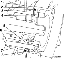
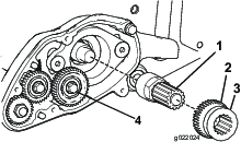
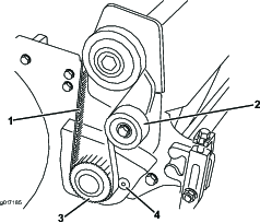
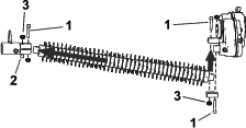
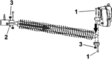
Using a hand-pump grease gun, lubricate the 2 groomer-shaft bearings (1 on each end). Pump only 2 to 3 pumps maximum to avoid permanently damaging the grease seals.

Note: When lubricating the main reel bearings, do not over grease because excess grease can work its way into the groomer-drive box or drip onto the turf.

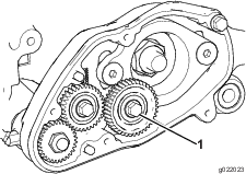
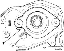
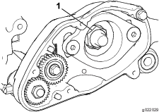
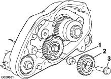
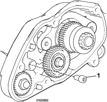
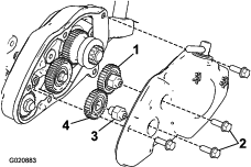
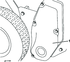
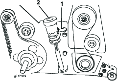
Every 500 operating hours, remove the cover from the groomer-drive box. Clean out all of the old grease and pack it with 85 g (3.0 oz) of synthetic grease (Toro part number 125-3511 or equivalent synthetic grease meeting ISO VG 220, NLGI 2 standards).

Inspecting the Blades

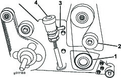
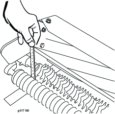
Inspect the grooming-reel blades frequently for damage and wear. Straighten bent blades with a pliers. Replace worn blades. When inspecting the blades, check to see that the right and left blade shaft end nuts are tight.

Note: If using spring steel blades, when one side of the blades become worn, remove the grooming reel, rotate it 180 degrees, and install it so that the unworn side is facing the direction of rotation.

Note: Because the groomer may introduce more debris (i.e., dirt and sand) into the cutting unit than what the reel would normally be exposed to, the bedknife and main reel should be checked for wear more frequently. This is especially important in sandy soil and/or when the groomer is set for penetration.

Replacing the Grooming Reel

Remove and replace the grooming reel using the following procedure:

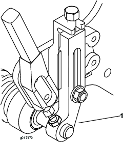
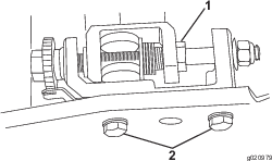
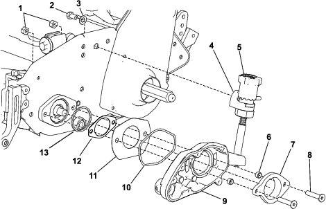
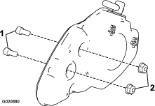
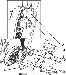
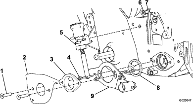
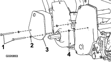
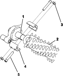
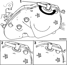
  1. Remove both bolts, nuts, and shaft clamps from one side of the groomer reel (Figure 23).

  2. Remove the inner bolt from the clamp on the other side and loosen the outer bolt.

    g246533
  3. Slide the reel assembly out of the clamp.

  4. Refer to Installing the Grooming Reel to install the reel as needed.

  5. Check the grooming reel height/depth setting.