| Maintenance Service Interval | Maintenance Procedure |
|---|---|
| Yearly |
|
Introduction
Read this manual carefully to learn how to operate and maintain your product properly. The information in this manual can help you and others avoid injury and product damage. Although Toro designs and produces safe products, you are responsible for operating the product properly and safely.
You may contact Toro directly at www.Toro.com for product safety and operation training materials, accessory information, help finding a dealer, or to register your product.
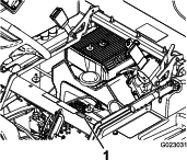
Whenever you need service, genuine Toro parts, or additional information, contact an Authorized Service Dealer or Toro Customer Service and have the model and serial numbers of your product ready. Figure 1 illustrates the location of the model and serial numbers on the product.
This manual identifies potential hazards and has safety messages identified by the safety-alert symbol (Figure 2), which signals a hazard that may cause serious injury or death if you do not follow the recommended precautions.

This manual uses 2 words to highlight information. Important calls attention to special mechanical information and Note emphasizes general information worthy of special attention.
The Multi Pro turf sprayer is a dedicated turf spray application vehicle and is intended to be used by professional, hired operators in commercial applications. It is primarily designed for spraying on well-maintained lawns in parks, golf courses, sports fields, and on commercial grounds.
This product complies with all relevant European directives; for details, please see the separate product specific Declaration of Conformity (DOC) sheet.
Warning
CALIFORNIA
Proposition 65 Warning
The engine exhaust from this product contains chemicals known to the State of California to cause cancer, birth defects, or other reproductive harm.
Use of this product may cause exposure to chemicals known to the State of California to cause cancer, birth defects, or other reproductive harm.
It is a violation of California Public Resource Code Section 4442 or 4443 to use or operate the engine on any forest-covered, brush-covered, or grass-covered land unless the engine is equipped with a spark arrester, as defined in Section 4442, maintained in effective working order or the engine is constructed, equipped, and maintained for the prevention of fire.
This spark ignition system complies with Canadian ICES-002
The enclosed Engine Owner's Manual is supplied for information regarding the US Environmental Protection Agency (EPA) and the California Emission Control Regulation of emission systems, maintenance, and warranty. Replacements may be ordered through the engine manufacturer.
Safety
Improper use or maintenance by the operator or owner can result in injury. To reduce the potential for injury, comply with these safety instructions and always pay attention to the safety-alert symbol, which means Caution, Warning, or Danger. Failure to comply with the instruction may result in personal injury or death.
The machine meets the requirements of SAE J2258.
Safe Operating Practices
Important: The machine is designed primarily as an off-road vehicle and is not intended for extensive use on public roads. When using the machine on public roads, follow all traffic regulations and use any additional accessories that may be required by law, such as lights, turn signals, slow-moving-vehicle (SMV) sign, and others as required.
The Multi-Pro 1750 Turf Sprayer was designed and tested to offer safe service when operated and maintained properly. Although hazard control and accident prevention partially are dependent upon the design and configuration of the machine, these factors are also dependent upon the awareness, concern, and proper training of the personnel involved in the operation, maintenance and storage of the machine. Improper use or maintenance of the machine can result in injury or death.
Not all of the attachments that adapt to the Multi-Pro 1750 Turf Sprayer are covered in this manual. See the specific operator’s manual provided with each attachment for additional safety instructions. Read these manuals.
To reduce the potential for injury or death, comply with the following safety instructions:
Supervisor's Responsibilities
-
Make sure that operators are thoroughly trained and familiar with the Operator's Manual, engine manual, and all labels on the sprayer.
-
Establish your own special procedures and work rules for unusual operating conditions (e.g., slopes too steep for sprayer operation).
Training
-
Read the Operator's Manual and other training material before operating the machine.
Note: If the operator(s) or mechanic(s) cannot read the manual language, it is the owner's responsibility to explain this material to them.
-
Become familiar with the safe operation of the equipment, operator controls, and safety signs.
-
All operators and mechanics should be trained. The owner is responsible for training the users.
-
Never allow untrained people to operate or service the equipment.
Note: Local regulations may restrict the age of the operator.
-
The owner/operator can prevent and is responsible for accidents or injuries occurring to other people, or damage to property.
Before Operating
-
Operate the machine only after reading and understanding the contents of this manual.
-
Never allow children to operate the sprayer.
-
Make sure that all operators are physically and mentally capable of operating the sprayer.
-
This sprayer is designed to carry the operator. Never carry any passengers on the sprayer.
-
Never operate the sprayer when ill, tired, or under the influence of drugs or alcohol.
-
Become familiar with the controls and know how to shut off the engine quickly.
-
Keep all shields, safety devices, and decals in place. If a shield, safety device, or decal is malfunctioning, illegible, or damaged, repair or replace it before operating the machine.
-
Wear appropriate clothing; including a safety glasses, long pants, substantial slip-resistant shoes, gloves, and hearing protection. Do not wear loose fitting clothing. Do not wear jewelry. Tie back long hair.
Caution
This machine produces sound levels in excess of 85 dBA at the operator’s ear and can cause hearing loss through extended periods of exposure.
Wear hearing protection when operating this machine.
-
Operate only in daylight or good artificial light.
-
Never spray while people, especially children or pets are nearby.
-
Before operating the sprayer, always check the designated areas of the sprayer that are stated in the Pre-Starting Checks in the Operation section. If the machine does not function correctly or is damaged in any way, do not use the sprayer. Make sure that the problem is corrected before the sprayer or attachment is operated.
-
Make sure the operator’s area is clean and free from chemical residue and debris buildup.
-
Ensure that all fluid line connectors are tight and all hoses are in good condition before applying pressure to the system.
Chemical Safety
Warning
-
Chemical substances used in the sprayer system may be hazardous and toxic to you, bystanders, animals, plants, soils or other property.
-
Carefully read and follow the chemical warning labels and Material Safety Data Sheets (MSDS) for all chemicals used and protect yourself according to the chemical manufacturer's recommendations. Ensure that as little skin as possible is exposed while using chemicals. Use appropriate Personal Protective Equipment (PPE) to guard against personal contact with chemicals, such as:
-
safety glasses, goggles, and/or face shield
-
respirator or filter mask
-
chemical resistant gloves
-
rubber boots or other substantial footwear
-
hearing protection
-
clean change of clothes, soap, and disposable towels, to be kept on-hand, in the event of a chemical spill.
-
Important: Keep in mind that there may be more than 1 chemical used, and information on each chemical should be assessed.Refuse to operate or work on the sprayer if this information is not available.Before working on a sprayer system, make sure that the system has been triple rinsed and neutralized according to the recommendations of the chemical manufacturer(s) and all of the valves have been cycled 3 times.Verify there is an adequate supply of clean water and soap nearby, and immediately wash off any chemicals that contact you.
-
Obtain proper training before using or handling chemicals.
-
Use the correct chemical for the job.
-
Follow the chemical manufacturer's instructions for the safe application of the chemical. Do not exceed recommended system application pressure.
-
Do not fill, calibrate, or clean the unit when people, especially children, or pets are in the area.
-
Handle chemicals in a well ventilated area.
-
Have clean water available especially when filling the spray tank.
-
Do not eat, drink, or smoke while working with chemicals.
-
Do not clean spray nozzles by blowing through them or placing in mouth.
-
Always wash your hands and other exposed areas as soon as possible after you finish working with chemicals.
-
Keep chemicals in their original packages and stored in a safe location.
-
Properly dispose of unused chemicals and chemical containers as instructed by the chemical manufacturer and your local codes.
-
Chemicals and fumes are dangerous; never enter the tank or place your head over or in the opening of a tank.
-
Follow all local, state, and federal regulations for spreading or spraying chemicals.
While Operating
Warning
Engine exhaust contains carbon monoxide, which is an odorless, deadly poison that can kill you.
Do not run engine indoors or in an enclosed area.
-
The operator should remain seated whenever the sprayer is in motion. The operator should keep both hands on the steering wheel whenever possible. Keep your arms and legs within the sprayer body at all times.
-
Failure to operate the sprayer safely may result in an accident, tip over of the sprayer, and serious injury or death. Drive carefully. To prevent tipping or loss of control:
-
Use extreme caution, reduce speed, and maintain a safe distance around sand traps, ditches, creeks, ramps, unfamiliar areas, or any areas that have abrupt changes in ground conditions or elevation.
-
Watch for holes or other hidden hazards.
-
Use extra caution when operating the sprayer on wet surfaces, in adverse weather conditions, at higher speeds, or with a full load. Stopping time and distance will increase with a full load.
-
Avoid sudden stops and starts. Do not go from reverse to forward or forward to reverse without first coming to a complete stop.
-
Slow down before turning. Do not attempt sharp turns or abrupt maneuvers or other unsafe driving actions that may cause a loss of sprayer control.
-
Before backing up, look to the rear and ensure that no one is behind you. Back up slowly.
-
Watch out for traffic when you are near or crossing roads. Always yield the right of way to pedestrians and other vehicles. This sprayer is not designed for use on streets or highways. Always signal your turns or stop early enough so that other people know what you plan to do. Obey all traffic rules and regulations.
-
The electrical and exhaust systems of the sprayer can produce sparks capable of igniting explosive materials. Never operate the sprayer in or near an area where there is dust or fumes in the air which are explosive.
-
If you are ever unsure about safe operation, stop work and ask your supervisor.
-
-
Do not touch the engine or muffler while the engine is running or soon after it has stopped. These areas may be hot enough to cause burns.
-
If the machine ever vibrates abnormally, stop immediately, wait for all motion to stop, and inspect the sprayer for damage. Repair all damage before resuming operation.
-
Before getting off the seat:
-
Stop the movement of the machine.
-
Place the range selector in the NEUTRAL position and set the parking brake.
-
Turn the ignition key to the OFF position.
-
Remove the ignition key.
Important: Do not park the machine on an incline.
-
-
Lightning can cause severe injury or death. If lightning is seen or thunder is heard in the area, do not operate the machine; seek shelter.
Braking
-
Slow down before you approach an obstacle. This gives you extra time to stop or turn away. Hitting an obstacle can damage the sprayer and its contents. More important, it can injure you.
-
Gross Vehicle Weight (GVW) has a major impact on your ability to stop and/or turn. Heavy loads and attachments make a sprayer harder to stop or turn. The heavier the load, the longer it takes to stop.
-
Turf and pavement are much more slippery when they are wet. It can take 2 to 4 times as long to stop on wet surfaces as on dry surfaces. If you drive through standing water deep enough to get the brakes wet, they will not work well until they are dry. After driving through water, you should test the brakes to make sure that they work properly. If they do not, drive slowly while putting light pressure on the brake pedal. This will dry the brakes out.
ROPS Safety
Note: For each machine covered in this Operator’s Manual, a cab installed by Toro is a ROPS.
-
Do not remove the ROPS from the machine.
-
Fasten the seat belt and ensure that you can release it quickly in an emergency. Always wear your seat belt when the roll bar is up or on a machine with a cab installed by Toro.
-
Check carefully for overhead obstructions and do not contact them.
-
Keep the ROPS in safe operating condition by thoroughly inspecting it periodically for damage and keeping all the mounting fasteners tight.
-
Replace any damaged ROPS component. Do not repair or alter it.
Operating on Hills and Rough Terrain
Operating the sprayer on a hill may cause tipping or rolling of the sprayer, or the engine may stall and you could lose headway on the hill. This could result in personal injury.
-
Do not accelerate quickly or suddenly apply the brakes when backing down a hill, especially with a load.
-
Never drive across a steep hill; always drive straight up or down or go around the hill.
-
If the engine stalls or you begin to lose headway while climbing a hill, gradually apply the brakes and slowly back straight down the hill.
-
Turning while traveling up or down hills can be dangerous. If you have to turn while on a hill, do it slowly and cautiously. Never make sharp or fast turns.
-
Heavy loads affect stability. Reduce the weight of the load and your speed when operating on hills.
-
Avoid stopping on hills, especially with a load. Stopping while going down a hill will take longer than stopping on level ground. If you must stop the sprayer, avoid sudden speed changes, which may initiate tipping or rolling of the sprayer. Do not suddenly apply the brakes when rolling backward, as this may cause the sprayer to overturn.
-
Reduce speed and load when operating on rough terrain, uneven ground, and near curbs, holes, and other sudden changes in terrain. Loads may shift, causing the sprayer to become unstable.
Warning
Sudden changes in terrain may cause abrupt steering wheel movement, possibly resulting in hand and arm injuries.
-
Grip the steering wheel loosely around the perimeter. Keep your hands clear of the steering wheel spokes.
Loading
The weight of the cargo can change the sprayer center of gravity and sprayer handling. To avoid loss of control and personal injury, follow these guidelines:
-
Liquid loads can shift. This shifting happens most often while turning, going up or down hills, suddenly changing speeds, or while driving over rough surfaces. Shifting loads can cause the sprayer to tip over.
-
When operating with a heavy load, reduce your speed and allow for sufficient braking distance. Do not suddenly apply the brakes. Use extra caution on slopes.
-
Be aware that heavy loads increase your stopping distance and reduce your ability to turn quickly without tipping over.
Maintenance
-
Only permit qualified and authorized personnel to maintain, repair, adjust, or inspect the sprayer.
-
Before servicing or making adjustments to the machine, shut off the engine, set the parking brake, and remove the key from the ignition to prevent someone from accidentally starting the engine.
-
To make sure that the entire machine is in good condition, keep all nuts, bolts, and screws properly tightened.
-
To reduce the potential for fire, keep the engine area free of excessive grease, grass, leaves, and accumulation of dirt.
-
Never use an open flame to check the level or leakage of fuel or battery electrolyte.
-
If the engine must be running to perform a maintenance adjustment, keep your hands, feet, clothing, and any parts of your body away from the engine and any moving parts. Keep everyone away.
-
Do not use open pans of fuel or flammable cleaning fluids when cleaning parts.
-
Do not adjust the ground speed governor. To ensure safety and accuracy, have an Authorized Toro Distributor check the ground speed.
-
Keep your body and hands away from pin-hole leaks or nozzles that eject high-pressure fluid. Use cardboard or paper to find leaks. Fluid escaping under pressure can penetrate skin and cause injury requiring surgery within a few hours by a qualified surgeon; otherwise, gangrene may result.
-
If major repairs are ever needed or assistance is required, contact an Authorized Toro Distributor.
-
To be sure of optimum performance and safety, always purchase genuine Toro replacement parts and accessories. Replacement parts and accessories made by other manufacturers could be dangerous. Altering this sprayer in any manner that may affect sprayer operation, performance, durability, or its use, may result in injury or death. Such use could void the product warranty.
Sound Power
This unit has a guaranteed sound power level of 98 dBA, which includes an Uncertainty Value (K) of 1 dBA.
Sound power level was determined according to the procedures outlined in ISO 11094.
Sound Pressure
This unit has a sound pressure level at the operator’s ear of 86 dBA, which includes an Uncertainty Value (K) of 1 dBA.
Sound pressure level was determined according to the procedures outlined in EN ISO 11201.
Hand-Arm Vibration
Measured vibration level for right hand = 3.00 m/s2
Measured vibration level for left hand = 3.20 m/s2
Uncertainty Value (K) = 1.6 m/s2
Measured values were determined according to the procedures outlined in EN ISO 20643.
Whole Body Vibration
Measured vibration level = 0.58 m/s2
Uncertainty Value (K) = 0.29 m/s2
Measured values were determined according to the procedures outlined in EN 1032.
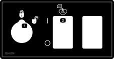
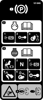
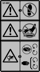
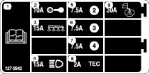
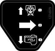
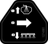
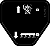
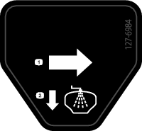
Safety and Instructional Decals
 |
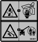
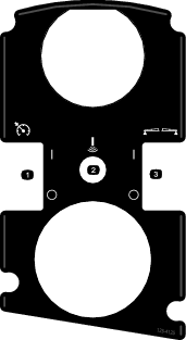
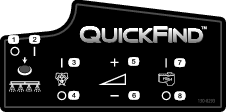
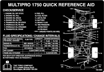
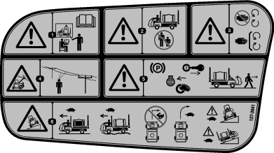
Safety decals and instructions are easily visible to the operator and are located near any area of potential danger. Replace any decal that is damaged or lost. |



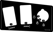
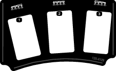
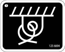
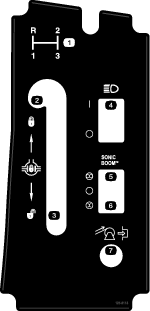


Setup
Note: Determine the left and right sides of the machine from the normal operating position.
Installing the Anti-Siphon Fill Receptacle
Parts needed for this procedure:
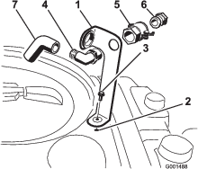
| 90° fitting | 1 |
| Quick coupler | 1 |
| Hose adapter | 1 |
| Fill-receptacle bracket | 1 |
| Flange-head bolt, 5/16 x 3/4 inch | 1 |
| Anti-siphon hose | 1 |
-
Place the fill-receptacle bracket over the threaded hole in the tank and secure it with a flange-head bolt (5/16 x 3/4 inch) (Figure 3).
-
Place the threaded end of the 90° elbow fitting through the bracket and thread the quick coupler onto it, securing it to the bracket (Figure 3).
Note: Install the fitting with the open end pointing toward the large opening in the bracket and toward the tank opening so that the water arcs into the tank when you fill it.
-
Install the hose adapter into the quick coupler (Figure 3).
-
Lock the adapter into place by swinging the levers toward the adapter and then secure them with the hairpin cotters (Figure 3).
-
Install the anti-siphon hose through the large opening on the bracket and onto the barbed end of the 90° elbow fitting (Figure 3).
Important: Do not lengthen the hose to allow contact with the tank fluids.
Checking the Boom-Hinge Springs
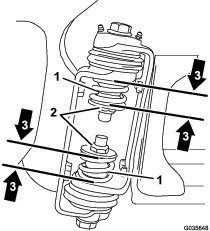
Important: Operating the spray system with the boom-hinge springs under the incorrect compression could damage the boom assembly. Measure the springs and use the jam nut to compress the springs to 4 cm (1-1/2 inches) if necessary.
The sprayer is shipped with the boom extensions swung forward to facilitate packaging of the machine. The springs are not fully tightened at the time of manufacture to allow the booms to be in this position for transit. Before operating the machine, the springs must be adjusted to the correct compression.
-
If necessary, remove the packing components that secure the right and left extension booms during shipping.
-
Support the booms while they are extended to the spray position.
-
At the boom hinge, measure the compression of the upper and lower springs while the booms are in their extended position (Figure 4).
-
All springs must be compressed until they measure 4 cm (1-1/2 inches).
-
Use the jam nut to compress any spring that measure greater than 4 cm (1-1/2 inches).
-
-
Repeat the procedure for each spring on both boom hinges.
-
Move the booms into the transport ‘X’ position. See Using the Boom-Transport Cradle for more information.
Learning More about Your Product
Parts needed for this procedure:
| Ignition key | 1 |
| Operator's Manual | 1 |
| Engine operator's manual | 1 |
| Parts Catalog | 1 |
| Operator training material | 1 |
| Registration card | 1 |
| Pre-delivery Inspection Sheet | 1 |
-
Read the manuals.
-
View the operator training material.
-
Complete the registration card and return it to Toro.
-
Store the documentation in a safe place.
Product Overview
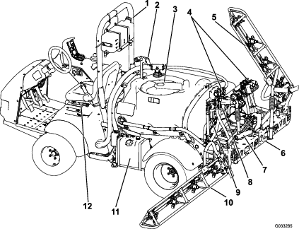
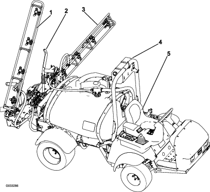
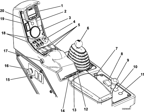
Accelerator Pedal
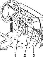
The accelerator pedal (Figure 8) gives you the ability to vary the ground speed of the sprayer. Pressing the pedal increases ground speed. Releasing the pedal will slow the sprayer and the engine will idle.
Clutch Pedal
The clutch pedal (Figure 8) must be fully pressed to disengage clutch when starting the engine or shifting transmission gears. Release the pedal smoothly when the transmission is in gear to prevent unnecessary wear on the transmission and other related parts.
Important: Do not ride the clutch pedal during operation. The clutch pedal must be fully out or the clutch will slip causing heat and wear. Never hold the vehicle stopped on a hill using the clutch pedal. Damage to the clutch may occur.
Brake Pedal
Use the brake pedal to stop or slow the sprayer (Figure 8).
Caution
Brakes can become worn or can be adjusted incorrectly resulting in personal injury.
If brake pedal travels to within 2.5 cm (1 inch) of the sprayer floor board, adjust or repair the brakes.
Parking Brake
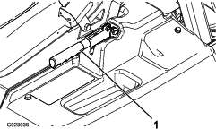
The parking brake is a large lever to the left of the seat (Figure 9). Engage the parking brake whenever you plan on leaving the seat to prevent accidental movement of the sprayer. To engage the parking brake, pull up and back on the lever. To disengage, push it forward and down. If the sprayer is parked on a steep grade, apply the parking brake and place blocks at the downhill side of the wheels.
Hill Assist
Hill assist prevents the sprayer from rolling or jerking by temporarily holding the sprayer on hilly terrain when the operator moves his/her foot from the brake pedal to the accelerator pedal. To engage hill assist, engage the clutch and push down on the brake pedal vigorously. When hill assist is engaged, the hill assist icon is displayed on the InfoCenter; refer to InfoCenter Icon Descriptions. Hill assist holds the machine for 2 seconds after releasing the brake pedal.
Note: As hill assist only temporarily holds the sprayer, it cannot be used in place of the parking brake.
Differential Lock
The differential lock allows rear axle to be locked for increased traction. The differential lock (Figure 7) may be engaged when the sprayer is in motion. Move the lever forward and to the right to engage the lock.
Note: Forward motion plus a slight turn may be required to engage or disengage the differential lock.
Caution
Turning with the differential lock on can result in loss of machine control. Do not operate with differential lock on when making sharp turns or at high speeds; refer to Adjusting Differential-lock Cable.
Choke Control
The choke control is a small knob behind the range selector (Figure 7). To start a cold engine, pull the choke control up. After the engine starts, regulate the choke to keep the engine running smoothly. As soon as possible, push the control down to the OFF position. A warm engine requires little or no choking.
Range Selector
The range selector (Figure 7) has 5 positions: 3 forward speeds, NEUTRAL, and REVERSE. The engine starts only when the range selector is in the NEUTRAL position.
Ignition Switch
The ignition switch (Figure 7), has 3 positions: STOP, RUN, and START. Rotate the key clockwise to the START position to start the engine and release it to the RUN position when started. Rotate the key to the STOP position to shut off the engine.
Headlight Switch
Toggle the switch to operate the headlights (Figure 7). Push it forward to turn the lights on and rearward to turn them off.
Throttle/Speed-Lock Switch
When the range selector is in the NEUTRAL position, you can use the accelerator pedal to speed up the engine, then push the switch below the InfoCenter forward to set the engine at that speed. This is necessary to run the chemical agitation while stationary or operating attachments such as the hand sprayer (Figure 7).
Important: The range selector must be in the NEUTRAL position and the parking brake must be set for the switch to work.
Fuel Gauge
The fuel gauge is located on top of the fuel tank, on the left side of the machine, and shows the amount of fuel in the tank.
Master-Boom Switch
The master-boom switch (Figure 7) is located on the side of the console and to the right of the operator. It allows you to start or stop the spray operation. Press the switch to enable or disable the spray system.
Boom-Section Switches
The boom switches are located on the control panel (Figure 7). Toggle each switch forward to turn the corresponding boom section on and rearward to turn them off. When the switch is turned on, a light on the switch illuminates. These switches affect the spray system only when the master-boom switch is on.
Pump Switch
The pump switch is located on the control panel to the right of the seat (Figure 7). Toggle this switch forward to run the pump or rearward to stop the pump.
Important: The pump switch will only engage when the engine is at low idle to avoid damaging the pump drive.
Application-Rate Switch
The application-rate switch is located on the control panel to the right of the seat (Figure 7). Press and hold the switch forward to increase the spray system pressure, or press and hold it rearward to decrease the pressure.
Supervisor (Rate-Lockout) Switch
The supervisor switch is located on the control panel to the right of the seat (Figure 7). Turn the key counterclockwise to the LOCK position to disable the application-rate switch, thereby keeping anyone from accidentally changing the application rate. Turn the key clockwise to the UNLOCKED position to enable the application-rate switch.
Boom Lift
The boom lift switches are located on the control panel and are used to raise the left and right boom respectively.
Hour Meter
The hour meter indicates the total number of hours the engine has run. This number is displayed on the first screen of the InfoCenter. The hour meter starts to function whenever the key is turned to the RUN position.
Sonic Boom (Optional)
The Sonic-Boom switch is a rocker switch used to operate the Sonic Boom. Toggle the switch forward for automatic, rearward for manual and center for off.
Foam-Marker Switch Locations (Optional)
If you install the Foam Marker kit, you will add switches to the control panel for controlling their operation. The sprayer comes with plastic plugs in these locations.
Regulating (Rate-Control) Valve
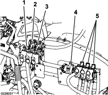
This valve, located behind the tank (Figure 10), controls the amount of fluid that is routed to the booms or the rate return to the tank.
Master-Boom Valve
The master-boom valve (Figure 10) is used to stop the flow to the flowmeter and boom valves.
Flowmeter
The flowmeter measures the flow rate of the fluid for use by the InfoCenter system (Figure 10).
Boom-Section Valves
These valves turn the 3 boom sections on or off (Figure 10).
Boom-Section-Bypass Valve
The boom bypass redirects the fluid flow for a boom section to the tank when you turn off the boom section. You can adjust the boom bypass to ensure that the boom pressure remains constant no matter how many booms sections are on. Refer to Adjusting the Master-Boom-Bypass Valve.
Agitation Valve
This valve is located on the rear of the tank (Figure 10). When agitation is on, the flow is directed through the agitation nozzles in the tank. When agitation is off, the flow is directed through the pump suction.
Pressure Gauge
The pressure gauge is located on the control panel (Figure 7). This gauge shows the pressure of the fluid in the system in psi and kPa.
InfoCenter LCD Display
The InfoCenter LCD display shows information about your machine and battery pack, such as the current battery charge, the speed, diagnostics information, and more (Figure 7).
For more information, refer to Using the InfoCenter.
Agitation-Throttle Valve
The agitation-throttle valve is used to reduce the flow available for the agitation circuit. It provides additional flow for the boom sections.
Note: Specifications and design are subject to change without notice.
| Weight with standard spray system, empty, without operator | 953 kg (2,100 lb) |
| Weight with standard spray system, full, without operator | 1,678 kg (3,700 lb) |
| Maximum gross vehicle weight (GVW) (on level ground) | 1,814 kg (4,000 lb) |
| Overall length with standard spray system | 343 cm (135 inches) |
| Overall height with standard spray system | 191 cm (75 inches) |
| Overall height with standard spray system to the top of the booms stored in the X position | 246 cm (97 inches) |
| Overall width with standard spray system booms stored in the ‘X’ position | 178 cm (70 inches) |
| Ground clearance | 14 cm (5.5 inches) |
| Wheel base | 155 cm (61 inches) |
| Tank capacity (includes the CE 5% overflow) | 662 L (175 US gallons) |
Attachments/Accessories
A selection of Toro approved attachments and accessories is available for use with the machine to enhance and expand its capabilities. Contact your Authorized Service Dealer or Distributor or go to www.Toro.com for a list of all approved attachments and accessories.
Operation
Note: Determine the left and right sides of the machine from the normal operating position.
Safety First
Please carefully read all of the safety instructions and decals in the safety section. Knowing this information could help you or bystanders avoid injury.
Preparing to Drive the Sprayer for the First Time
Checking the Engine Oil
The engine is shipped with oil in the crankcase; however, the level of oil must be checked before you first start the engine and after you have run it.
-
Position the machine on a level surface.
-
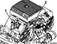
Remove the dipstick and wipe it with a clean rag (Figure 11).
-
Insert the dipstick into the tube and make sure that it is seated fully. Remove the dipstick and check the oil level.
-
If the oil level is low, remove the filler cap from the valve cover (Figure 11) and pour oil into the opening until the oil level is up to the FULL mark on the dipstick; refer to Servicing the Engine Oil for the proper oil type and viscosity. Add the oil slowly and check the level often during this process. Do not overfill.
-
Install the dipstick firmly in place.
Checking the Tire Pressure
Check the tire pressure every 8 hours or daily to ensure proper levels. Fill the tires to 138 kPa (20 psi). Also, check the tires for wear or damage.
Adding Fuel
Danger
In certain conditions, gasoline is extremely flammable and highly explosive. A fire or explosion from gasoline can burn you and others and can damage property.
-
Fill the fuel tank outdoors, in an open area, when the engine is cold. Wipe up any gasoline that spills.
-
Never fill the fuel tank inside an enclosed trailer.
-
Do not fill the fuel tank completely full. Add gasoline to the fuel tank until the level is 6 to 13 mm (1/4 to 1/2 inch) below the bottom of the filler neck. This empty space in the tank allows gasoline to expand.
-
Never smoke when handling gasoline, and stay away from an open flame or where gasoline fumes may be ignited by a spark.
-
Store gasoline in an approved container and keep it out of the reach of children. Never buy more than a 30-day supply of gasoline.
-
Do not operate without entire exhaust system in place and in proper working condition.
Danger
In certain conditions during fueling, static electricity can be released causing a spark which can ignite the gasoline vapors. A fire or explosion from gasoline can burn you and others and can damage property.
-
Always place gasoline containers on the ground away from your vehicle before filling.
-
Do not fill gasoline containers inside a vehicle or on a truck or trailer bed because interior carpets or plastic truck bed liners may insulate the container and slow the loss of any static charge.
-
When practical, remove gas-powered equipment from the truck or trailer and refuel the equipment with its wheels on the ground.
-
If this is not possible, then refuel such equipment on a truck or trailer from a portable container, rather than from a gasoline-dispenser nozzle.
-
If a gasoline-dispenser nozzle must be used, keep the nozzle in contact with the rim of the fuel tank or container opening at all times until fueling is complete.
-
For best results, use only clean, fresh (less than 30 days old), unleaded gasoline with an octane rating of 87 or higher ((R+M)/2 rating method).
-
ETHANOL: Gasoline with up to 10% ethanol (gasohol) or 15% MTBE (methyl tertiary butyl ether) by volume is acceptable. Ethanol and MTBE are not the same. Gasoline with 15% ethanol (E15) by volume is not approved for use. Never use gasoline that contains more than 10% ethanol by volume, such as E15 (contains 15% ethanol), E20 (contains 20% ethanol), or E85 (contains up to 85% ethanol ). Using unapproved gasoline may cause performance problems and/or engine damage which may not be covered under warranty.
-
Do not use gasoline containing methanol.
-
Do not store fuel either in the fuel tank or fuel containers over the winter unless a fuel stabilizer is used.
-
Do not add oil to gasoline.
Filling the Fuel Tank
The fuel tank capacity is approximately 19 L (5 US gallons).
Note: The fuel-tank cap contains a gauge which shows the fuel level; check it frequently.
-
Shut the engine off and set the parking brake.
-
Clean the area around the fuel-tank cap (Figure 12).

-
Remove the fuel-tank cap.
-
Fill the tank to about 2.5 cm (1 inch) below the top of the tank, (bottom of the filler neck). This space in the tank allows gasoline to expand. Do not overfill.
-
Install the fuel-tank cap securely.
-
Wipe up any fuel that may have spilled.
Performing the Pre-Starting Checks
Check the following items each time you begin using the sprayer for the day:
-
Check the tire pressure.
Note: These tires are different than car tires; they require less pressure to minimize turf compaction and damage.
-
Check all fluid levels and add the appropriate amount of specified fluids, if any are found to be low.
-
Check the brake pedal operation.
-
Check to see that the lights are working.
-
Turn the steering wheel to the left and right to check steering response.
-
Check for oil leaks, loose parts, and any other noticeable malfunctions. Make sure that the engine is off and all moving parts have stopped before checking for oil leaks, loose parts, and other malfunctions.
If any of the above items are not correct, notify your mechanic or check with your supervisor before taking the sprayer out for the day. Your supervisor may want you to check other items on a daily basis, so ask what your responsibilities are.
Driving the Sprayer
Starting the Engine
-
Sit in the operator's seat, insert the key into the ignition switch, and rotate the key clockwise to the RUN position.
-
Press the clutch and move the range selector to the NEUTRAL position.
-
Ensure that the pump switch is in the OFF position.
-
If the engine is cold, pull the choke knob up.
Important: Do not use the choke if the engine is warm.
-
Turn the key to the START position until the engine starts.
Important: Do not hold the key in the START position for more than 10 seconds. If the engine has not started after 10 seconds, wait 1 minute before trying again. Do not attempt to push or tow the sprayer to start the engine.
-
Once the engine starts, push the choke knob down slowly.
Driving
-
Release the parking brake.
-
Fully press the clutch pedal.
-
Move the gear shift lever to first gear.
-
Release the clutch pedal smoothly while pressing the accelerator pedal.
-
When the vehicle gains enough speed, remove your foot from the accelerator pedal, fully press the clutch pedal, move the gear shift lever to the next gear and release the clutch pedal while pressing the accelerator pedal. Repeat the procedure until the desired speed is attained.
Important: Always stop the vehicle before shifting from a forward gear to reverse or from reverse to a forward gear.
Note: Avoid long periods of engine idling.
Use the chart that follows to determine the ground speed of an empty vehicle at 3400 rpm.
Gear Ratio Speed (km/h) Speed (mph) 1 66.4:1 5.6 3.5 2 38.1:1 9.8 6.1 3 19.6:1 19.2 11.9 R 80.7:1 4.7 2.9 Note: Leaving the ignition switch in the ON position for long periods of time without running the engine will discharge the battery.
Important: Do not attempt to push or tow the vehicle to get it started. Damage to the drive train could result.
Setting the Throttle Lock
Note: You must have the parking brake and spray pump on and the range selector in the NEUTRAL position to set the throttle lock.
-
Press down on the accelerator pedal to obtain the desired engine rpm.
-
Toggle the throttle lock switch on the control panel to the ON position.
-
To release the throttle lock, toggle the switch to the OFF position, or press the brake or clutch pedal.
Setting the Speed Lock
Note: Before setting the speed lock, you must sit in the operator’s seat with the parking brake off, the pump on, and the range selector in gear.
-
Press down on the accelerator pedal to obtain the desired engine speed.
-
Toggle the speed lock switch on the control panel to the ON position.
-
To release the speed lock, toggle the switch to the OFF position, or press the brake or clutch pedal.
Shutting Off the Engine
-
Press the clutch and apply the brake to stop the sprayer.
-
Pull the parking-brake lever up and back to set it.
-
Move the range selector out of gear into the NEUTRAL position.
-
Turn the ignition key to the STOP position.
-
Remove the key from the switch to prevent accidental starting.
Breaking in a New Sprayer
To provide proper performance and long sprayer life, follow these guidelines for the first 100 operating hours:
-
Check the fluid and engine-oil levels regularly and be alert for indications of overheating in any component of the sprayer.
-
After starting a cold engine, let it warm up for about 15 seconds before accelerating.
-
To optimize the brake system, burnish (break in) the brakes as follows:
-
Load 454 L (120 US gallons) of water into the tank.
-
Move the machine to and open-level area.
-
Drive the machine at full speed.
-
Apply the brakes rapidly.
Note: Stop the machine in a straight line without locking up the tires.
-
Wait 1 minute to allow the brakes to cool.
-
Repeat steps 3 through 5 an 9 additional times.
-
-
Avoid racing the engine.
-
Vary the sprayer speed during operation. Avoid fast starts and quick stops.
-
Refer to for any special, low-hour checks.
Adjusting the Booms to Level
You can use the following procedure to adjust the actuators on the center boom to keep the left and right booms at level.
-
Extend the booms to the spray position.
-
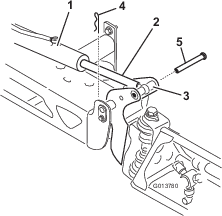
Remove the cotter pin from the pivot pin (Figure 13).
-
Lift up on the boom and remove the pin (Figure 13), and slowly lower the boom to the ground.
-
Inspect the pin for any damage, and replace it if necessary.
-
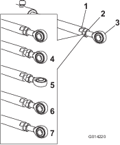
Use a wrench on the flat sides of the actuator rod to immobilize it, then loosen the jam nut to allow the eyelet rod to be manipulated (Figure 14).
-
Turn the eyelet rod in the actuator rod to shorten or lengthen the extended actuator to the desired position (Figure 14).
Note: Turn the eyelet rod in half or complete revolutions to allow the reassembly of the rod to the boom.
-
With the eyelet rod in the desired position, tighten the jam nut to secure the actuator and eyelet rod.
-
Raise the boom to align the pivot with the actuator rod. While holding the boom, insert the pin through both boom pivot and actuator rod (Figure 13).
-
With the pin in place, release the boom and secure the pin with the cotter previously removed.
-
Repeat this procedure for each actuator rod bearing, if necessary.
Operating the Sprayer
To operate the Multi Pro Sprayer, first fill the spray tank, then apply the solution to the work area, and finally clean the tank. It is important that you complete all 3 of these steps in succession to avoid damaging the sprayer. For example, do not mix and add chemicals in the spray tank at night and then spray in the morning. This would lead to separation of the chemicals and to possible damage to the sprayer components.
Caution
Chemicals are hazardous and can cause personal injury.
-
Read the directions on the chemical labels before handling the chemicals, and follow all manufacturer recommendations and precautions.
-
Keep chemicals away from your skin. Should contact occur, wash the affected area thoroughly with soap and clean water.
-
Wear goggles and any other protective equipment recommended by the chemical manufacturer.
The Multi Pro Sprayer has been specifically designed to have high durability in order to give it the long sprayer life you need. Different materials have been chosen for specific reasons at different locations on your sprayer to meet this goal. Unfortunately, there is no single material which is perfect for all foreseeable applications.
Some chemicals are more aggressive than others, and each chemical interacts differently with various materials. Some consistencies (e.g., wettable powders, charcoal) are more abrasive and lead to higher-than-normal wear rates. If a chemical is available in a formulation that would provide increased life to the sprayer, use this alternative formulation.
As always, remember to clean your sprayer thoroughly after all applications. This will do the most to ensure that your sprayer has a long and trouble-free life.
Using the Differential Lock
The differential lock increases the sprayer’s traction by locking the rear wheels so that 1 wheel will not spin out. This can help when you have heavy loads to haul on wet turf or slippery areas, going up hills, and on sandy surfaces. It is important to remember, however, that this extra traction is intended for temporary or limited use. Its use does not replace the safe operation, already discussed concerning steep hills and heavy loads.
The differential lock causes the rear wheels to turn at the same speed. When using differential lock your ability to make sharp turns is somewhat restricted and the tires may scuff the turf. Use the differential lock only when needed, at slower speeds and only in first or second gear.
Warning
Tipping or rolling the sprayer on a hill will cause serious injury.
-
The extra traction available with the differential lock can be enough to get you into dangerous situations such as climbing slopes that are too steep to turn around. Be extra careful when operating with the differential lock on, especially on steeper slopes.
-
If the differential lock is on when making a sharp turn at a higher speed and the inside rear wheel lifts off the ground, there may be a loss of control which could cause the sprayer to skid. Use the differential lock only at slower speeds.
Filling the Fresh-Water Tank
Always fill the fresh-water tank with clean water before handling or mixing any chemicals.
The fresh-water tank is located on the left side of the ROPS bar. It supplies a source of fresh water for you to wash chemicals off your skin, eyes, or other surfaces in the case of accidental exposure.
To open the fresh-water tank spigot, turn the lever on the spigot.
Filling the Spray Tank
Install the Chemical Pre-Mix Kit for optimal mixing and exterior tank cleanliness.
Important: Ensure that the chemicals you will be using are compatible for use with Viton (see the manufacturer's label; it should indicate if it is not compatible). Using a chemical that is not compatible with Viton will degrade the O-rings in the sprayer, causing leaks.
Important: Verify that the proper application rate has been set prior to filling the tank with chemicals.
-
Stop the sprayer on a level surface, move the range selector to the NEUTRAL position, shut off the engine, and set the parking brake.
-
Ensure that the tank drain valve is closed.
-
Determine the amount of water needed to mix the amount of chemical you need as prescribed by the chemical manufacturer.
-
Open the tank cover on the spray tank.
Note: The tank cover is located in the center of the top of the tank. To open it, turn the front half of the cover counterclockwise and swing it open. You can remove the strainer inside for cleaning. To seal the tank, close the cover and rotate the front half clockwise.
-
Add 3/4 of the required water to the spray tank using the anti-siphon fill receptacle.
Important: Always use fresh clean water in the spray tank. Do not pour concentrate into an empty tank.
-
Start the engine and set the pump switch to the ON position.
-
Press the accelerator pedal to the floor and set the throttle lock to the ON position.
-
Set the master-boom switch to the OFF position.
-
Turn the agitation valve to the ON position.
-
Add the proper amount of chemical concentrate to the tank as directed by the chemical manufacturer.
Important: If you are using a wettable powder without full agitation, mix the powder with a small amount of water to form a slurry before adding it to the tank.
-
Add the remaining water to the tank.
Operating the Booms
The boom lift switches on the sprayer control panel allows you to move the booms between the TRANSPORT position and the SPRAY position without leaving the operator's seat. It is recommended to change boom positions while the machine is not moving.
Changing the Boom Position
-
Stop the sprayer on level ground.
-
Use the boom lift switches to lower the booms.
Note: Wait until the booms reach the full, extended SPRAY position.
-
When the booms need to be retracted, stop the sprayer on level ground.
-
Use the boom lift switches to raise the booms, until they have moved completely into boom-transport cradle forming the ‘X’ transport position and the boom cylinders are fully retracted.
Important: To prevent damage to the boom actuator cylinder, make sure that the actuators are fully retracted before transport.
Using the Boom-Transport Cradle
The sprayer is equipped with a boom-transport cradle that has a unique safety feature. In the event of accidental boom contact with a low overhead object while in the TRANSPORT position, you can push the boom(s) out of the transport cradles. If this occurs, the booms will come to rest in a near horizontal position to the rear of the vehicle. While the booms will not be damaged due to this movement, they should be immediately put back into the transport cradle.
Important: You can damage the booms if you transport them in any position other than the ‘X’ transport position using the boom-transport cradle.
To put the booms back into the transport cradle, lower the boom(s) to the SPRAY position, and then raise the boom(s) back into the TRANSPORT position. Make sure that the boom cylinders are fully retracted to prevent actuator rod damage.
Spraying
Important: To ensure that your solution remains well mixed, use the agitation feature whenever you have a solution in the tank. For agitation to work, you must have the pump on and the engine running above an idle. If you stop the vehicle and need agitation on: set the parking brake, turn the pump on, press the accelerator pedal to floor, and switch the throttle lock to the ON position.
Note: This procedure assumes that the pump is on from the Operating the Sprayer procedure.
-
Lower the booms into position.
-
With the master-boom switch in the OFF position, set the 3 boom switches to the ON position.
-
Drive to the location where you will be spraying.
-
Set the master-boom switch to the ON position to begin spraying.
Note: The InfoCenter will show the booms with the spray on.
Note: When the tank is nearly empty, the agitation may cause foaming in the tank. To prevent this, turn the agitation valve off. Alternatively, you can use an anti-foaming agent in the tank.
-
Use the rate switch to adjust and set a target.
-
When finished spraying, set the master-boom switch to the OFF position to turn off all booms, then set the pump switch to the OFF position.
Spraying Tips
-
Do not overlap areas that you have previously sprayed.
-
Watch for plugged nozzles. Replace all worn or damaged nozzles.
-
Use the master-boom switch to stop the spray flow before stopping the sprayer. Once stopped, place the range selector in the NEUTRAL position and use the neutral engine speed lock to hold the engine speed up to keep the agitation running.
-
You will obtain better results if the sprayer is moving when you turn the booms on.
-
Watch for changes in the application rate that may indicate that your speed has changed beyond the range of the nozzles or there is a problem with the spray system.
Cleaning the Sprayer
Important: You must always empty and clean the sprayer immediately after each use. Failure to do so may cause the chemicals to dry or thicken in the lines, clogging the pump and other components.
Note: Install the Tank Clean Rinse Kit for optimal tank cleaning.
-
Stop the sprayer, set the parking brake, place the range selector in the NEUTRAL position, and shut off the engine. The tank will drain to the left side of the machine.
-
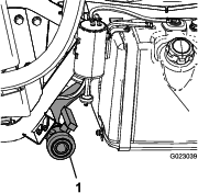
Locate the tank drain valve on the left side of the machine (Figure 15).
Note: The valve is behind the left fender bracket next to the fuel tank.
-
Remove the valve from the bracket, and let the valve rest on the ground.
-
Open the valve to drain any unused material from the tank and dispose of it according to local codes and the material manufacturer's instructions (Figure 15).
Note: This allows any residual material in the line to drain.
-
When the tank has drained completely, close the drain valve and install the valve onto the bracket (Figure 15).
-
Rinse the inside of the tank with at least 22 L (6 US gallons) of clean fresh water and close the cover.
Note: You can use a cleaning/neutralizing agent in the water as needed. On the final rinse, use only clean, clear water.
-
Start the engine.
-
Set the pump switch to the ON position and use the application-rate switch to increase the pressure to a high setting.
-
With the range selector in the NEUTRAL position, press the accelerator pedal to the floor and toggle the throttle lock switch to the ON position.
-
Ensure that the agitation valve is in the ON position.
-
Set the master-boom switch and boom-control switches to the ON position to begin spraying.
-
Allow all of the water in the tank to spray out though the nozzles.
-
Check the nozzles to ensure that they are all spraying correctly.
-
Set the master-boom switch to the OFF position, set the pump switch to the OFF position, and shut off the engine.
-
Repeat steps 6 through 14 at least 2 more times to ensure that the spray system is fully cleaned.
-
On the last cycle, run the last few gallons of water through the drain valve to clear the drain tubing.
-
Clean the strainer; refer to Cleaning the Suction Strainer.
Important: If you used wettable powder chemicals, clean the strainer after each tank.
-
Using a garden hose, spray off the outside of the sprayer with clean water.
-
Remove the nozzles and clean them by hand.
Note: Replace damaged or worn nozzles.
Using the InfoCenter
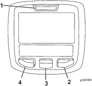
The InfoCenter LCD display shows information about your machine, such as the operating status, various diagnostics, and other information about the machine (Figure 16). There is a splash screen and main information screen on the InfoCenter. You can switch between the splash screen and main information screen at any time by pressing any of the InfoCenter buttons and then selecting the appropriate directional arrow.
-
Left button, Menu access/Back button—press this button to access the InfoCenter menus. You can also use it to exit any menu that you are currently using.
-
Middle button—use this button to scroll down menus.
-
Right button—use this button to open a menu where a right arrow indicated additional content.
Note: The purpose of each button may change depending on what is required at the time. Each button has an icon displaying its current function.
Starting the InfoCenter
-
Insert the key into the starter switch and rotate it to the ON position.
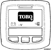
Note: The InfoCenter illuminates and displays the initialization screen (Figure 17).
-
After approximately 15 seconds, the home screen will appear; press the center selection button to display the information context (Figure 18).
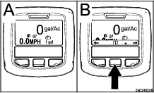
Note: Rotating the starter switch to the START position and starting the engine causes the values indicated in the InfoCenter display to reflect the running machine.
Accessing the Settings Menu
-
Start the InfoCenter; refer to Starting the InfoCenter.
Note: The Home screen displays.
-
Press the center selection button to access the Information context.
Note: The information context icon displays.
-
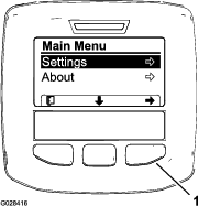
Press the center selection button to access the Main Menu (Figure 20).
-
Press the right selection button to display to the Settings sub-menus.
Note: The Main Menu displays with the Settings option selected.
Note: Pressing the center selection button (the button below the down arrow icon in the display) moves the selected option down.
Changing the Units of Measure (English and Metric)
-
Access the Settings menu; refer to Accessing the Settings Menu.
-
To change the unit of measure, press the right selection button to change the listed units of measure (Figure 21).
-
English: mph, gallons, and acre
-
Turf: mph, gallons, and 1000 ft2
-
SI (metric): kph, liter, hectare
Note: The display switches between English and metric units.
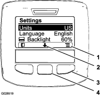
Note: Pressing the left selection button saves your selection, exit the Settings menu, and return to the Main Menu.
-
-
To change the language used in the display, pressing the center selection button (the button below the down arrow in the display) to move the selected option to Language (Figure 21).
-
Press the right selection button (the button below the list icon in the display) to highlight the listed language used in the display (Figure 21).
Note: Available languages include: English, Spanish, French, German, Portuguese, Danish, Dutch, Finnish, Italian, Norwegian, and Swedish.
-
Press the left selection button to save your selection(s), exit the Settings menu, and return to the Main Menu (Figure 20).
-
Press the left selection button to return to the Home screen (Figure 21).
Adjusting the Backlighting and Contrast Levels of the Display
-
Access the Settings menu; refer to Accessing the Settings Menu.
-
To adjust the backlight level of the display, press the center selection button (the button below the down arrow icon in the display) to move the selected option down to the Backlight setting (Figure 22).
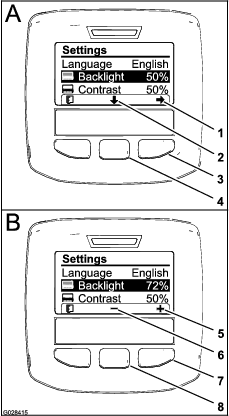
-
Press the right selection button to display the value adjustment context (Figure 22).
Note: The display shows a (―) icon over the center selection button and a (+) icon over the right selection button.
-
Use the center selection button and right selection button to change the brightness level of the display (Figure 22).
Note: As you change the brightness value, the display changes the selected brightness level.
-
Press the left selection button (the button below the list icon in the display) to save your selection, exit the Backlight menu, and return to the Settings menu (Figure 22).
-
To adjust the contrast level of the display, press the center selection button (the button below the down arrow icon in the display) to move the selected option down to the Contrast setting (Figure 22).
-
Press the right selection button to display the value adjustment context (Figure 22).
Note: The display shows a (―) icon over the center selection button and a (+) icon over the right selection button.
-
Press the left selection button (the button below the list icon in the display) to save your selection, exit the Contrast menu, and return to the Settings menu (Figure 22).
-
Press the left selection button to exit the Settings menu and return to the Main Menu (Figure 20 and Figure 22).
-
Press the left selection button to return to the Home screen (Figure 22).
InfoCenter Icon Descriptions
 | Information icon |
 | Next |
 | Previous |
 | Scroll down |
 | Enter |
 | Change the next value in the list |
 | Increase |
 | Decrease |
 | Active screen |
 | Inactive screen |
 | Go to the home screen |
 | Active home screen |
 | Save value |
 | Exit menu |
 | Hour meter |
 | Correct PIN code entered |
 | Check PIN entry/Calibration verification |
 | Parking brake active |
 | Hill-assist |
 | Master boom On/Boom sprayer Off |
 | Master boom On/Boom sprayer On |
 | Full spray tank |
 | Spray tank at half |
 | Tank level low |
 | Empty spray tank |
 or or  | TURF units (1,000 ft²) |
 | Area sprayed |
 | Volume sprayed |
 | Adjust tank volume |
 | Home screen |
 | Clear active area |
 | Clear all areas |
 | Adjust digit |
 | Select the next area for accumulation |
 | Throttle lock is active |
Using the Menus
To access the InfoCenter menu system, press the menu access button while at the main screen. This will bring you to the main menu. Refer to the following tables for a synopsis of the options available from the menus:
| Calibration | |
| Menu Item | Description |
| Test Speed | This menu sets the test speed for calibration. |
| Flow Calibration | This menu calibrates the flow meter. |
| Speed Calibration | This menu calibrates the speed sensor. |
| Settings Menu | |
| Menu Item | Description |
| Low Tank Alert | This menu sets the low tank volume alert. |
| Units | This menu changes the units used by the InfoCenter. The menu choices are English, SI (Metric), and Turf. |
| Language | This menu changes the language used on the InfoCenter. |
| LCD Backlight | This menu increases or decreases the brightness of the LCD display. |
| LCD Contrast | This menu changes the contrast between the dark and light areas of the LCD display. |
| Protected Menus | This menu grants access to protected menus. |
| Service Menu | |
| Menu Item | Description |
| Faults | This menu displays the most recent faults and last cleared fault. |
| Hours | This menu lists the total number of hours for key on, machine run, and pump on. It also lists the service due hour and service reset. |
| Diagnostics Menu | |
| Menu Item | Description |
| Pumps | This menu accesses the pump inputs, momentary rinse, and time rinse options. |
| Booms | This menu accesses the boom inputs, qualifiers, and outputs. |
| Throttle Lock | This menu accesses the throttle lock inputs, quantifiers, and outputs. |
| Engine Run | This menu accesses the engine run inputs and outputs. |
| About Menu | |
| Menu Item | Description |
| Model | This menu lists the model number of the machine. |
| Serial Number | This menu lists the serial number of the machine. |
| S/W Rev. | This menu lists the revision number of the machine software. |
Note: If you inadvertently change the language or contrast to a setting where you can no longer understand or view the display, contact your Authorized Toro Distributor for assistance in resetting the display.
Using the Settings Menu
Setting the Tank-Level Alert
-
From the Main Menu, press the center selection button to navigate to the Settings menu.
-
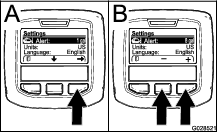
Press the center selection button to highlight the Alert setting (Figure 23).
Note: The (-) and (+) icons will appear above the center and right selection buttons.
-
Press the right selection button (Figure 23).
-
Use the center or right selection buttons to enter the minimum quantity in the tank when the alert displays during sprayer operation (Figure 23).
Note: Holding the button down increases the value of the tank alert by 10%.
-
Press the left selection button to save and return to the main menu.
Entering the PIN into the InfoCenter
Note: Entering the PIN allows you to change the access protected settings and maintain the password.
Note: The factory entered PIN number is 1234.
-
From the Main Menu, press the center selection button to navigate to the Settings menu.
-
Press the center selection button to highlight the Protected Menus setting.
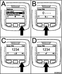
-
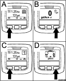
Press the right select button to select Protected Menus (A of Figure 24).
-
Set the numerical value in the PIN entry screen by pressing the following selection buttons:
-
Once the right-most value is set, press the right selection button.
Note: The checkmark icon appears above the center selection button (D of Figure 24).
-
Press the center selection button (D of Figure 24) to enter the password.
Changing the PIN
-
Enter the current PIN; refer to steps 1 through 6 in Entering the PIN into the InfoCenter.
-
From the Main Menu, press the center selection button to navigate to the Settings menu.
-
Press the center selection button to highlight the Protected Menus setting.
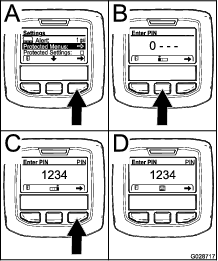
-
Press the right select button to select Protected Menus (A of Figure 25).
-
Enter the new PIN into the entry screen by pressing the following selection buttons:
-
Once the right-most value is set, press the right selection button.
Note: The Save icon appears above the center selection button (D of Figure 25).
-
Wait until the InfoCenter displays the “value saved message” and the red indicator light illuminates.
Setting the Protect Settings
Important: Use this function to lock and unlock the application rate.
Note: You must know the 4-digit PIN number to change settings for functions in the protected menus.
-
From the Main Menu, press the center selection button to navigate to the Settings menu.
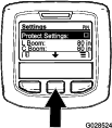
-
Press the center selection button to highlight the Protect Settings entry.
Note: If there is no X in the box to the right of Protect Settings entry, the sub-menus for L Boom, C Boom, R Boom, and Reset Defaults are not locked with the PIN (Figure 27).
-
Press the right selection button.
Note: The PIN entry screen appears.
-
Enter the PIN; refer to step 4 in Entering the PIN into the InfoCenter.
-
Once the right-most value is set, press the right selection button.
Note: The Check Mark icon appears above the center selection button.
-
Press the center selection button.
Note: The sub-menus for L Boom, C Boom, R Boom, and Reset Defaults appear.
-
Press the center selection button to highlight the Protect Settings entry.
-
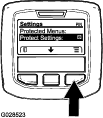
Press the right selection button.
Note: An X appears in the box to the to the right of Protect Settings entry (Figure 27).
-
Wait until the InfoCenter displays the “value saved message” and the red indicator light illuminates.
Note: The sub-menus below the Protected Menus entry are locked with the PIN.
Note: To access the sub-menus, highlight the Protect Settings entry, press the right selection button, enter the PIN, and when the Check Mark icon appears—press the center selection button.
Resetting the Boom Section Sizes to Default
-
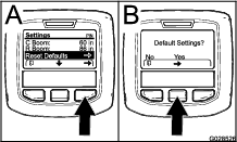
Press the center selection button to navigate to the Reset Default entry (Figure 28).
-
Press the right selection button to select Reset Default.
-
In the Default Settings screen, press the left selection button for No or the right selection button for Yes (Figure 28).
Note: Selecting Yes restores the boom section sizes to the factory setting.
Changing the Hill Assist Setting
Hill assist is defaulted on but can be turned off as follows:
-
From the Main Menu, press the center selection button to navigate to the Settings menu.
-
Scroll down to Hill Assist and press the center selection button to enter the Hill Assist settings menu.
-
In the Hill Assist settings menu, select Off.
Calibrating the Sprayer Flow
Operator supplied equipment: Stop watch capable of measuring ± 1/10 second and a container graduated in 50 ml (1 fl oz) increments.
Note: Before using the sprayer for the first time, if you change the nozzles, or as needed, calibrate the sprayer flow, speed, and boom bypass.
-
Fill the spray tank with clean water.
Note: Ensure that there is enough water in the tank to complete the calibration.
-
Set the parking brake and turn the engine on.
-
Set the pump switch to the ON position, and turn on the agitation.
-
Press down on the accelerator pedal until you reach the maximum engine speed, and toggle the throttle lock switch to the ON position.
-
Set all 3 boom switches and the master-boom switch to the ON position.
-
Turn the supervisor (rate-lockout) switch to the UNLOCK position.
-
Prepare to perform a catch test using the graduated container.
-
Start at 2.75 bar (40 psi) and use the application-rate switch to adjust the spray pressure so a catch test yields the amounts listed in the table below.
Note: Repeat the test 3 times and use the average.
Nozzle Color Milliliters collected in 15 seconds Ounces collected in 15 seconds Yellow 189 6.4 Red 378 12.8 Brown 473 16.0 Gray 567 19.2 White 757 25.6 Blue 946 32.0 Green 1,419 48.0 -
Once the catch test has yielded the amounts listed in the table above, set the supervisor rate lock out switch to the LOCK position.
-
Turn off the master-boom switch.
-
On the InfoCenter, navigate to the Calibration menu and select Flow Calibration as follows:
Note: Selecting the Home Screen icon at any time cancels calibrations.
-
Press the center button on the InfoCenter twice to access the menus.
-
Enter the calibration menu by pressing the right button on the InfoCenter.
-
Select Flow Cal by highlighting Flow Cal and press the right button on the InfoCenter.
-
In the next screen, enter the known quantity of water that will be sprayed out of the booms for the calibration procedure; refer to the chart below.
-
Once the known quantity has been entered press the right button on the InfoCenter.
-
-
Using the plus (+) and minus (-) symbols, enter the flow volume according to the table below.
Nozzle Color Liters US Gallons Yellow 42 11 Red 83 22 Brown 106 28 Gray 125 33 White 167 44 Blue 208 55 Green 314 83 -
Turn on the master-boom switch for 5 minutes.
Note: As the machine sprays, the InfoCenter displays the quantity of fluid that it is counting.
-
After the 5 minute duration of spraying click the check mark by pressing the center button on the InfoCenter.
Note: It is acceptable if the gallons displayed during the calibration process do not match the known quantity of water entered into the InfoCenter.
-
After 5 minutes, turn off the master-boom switch and select the check mark on the InfoCenter.
Note: Calibration is now complete.
Calibrating the Sprayer Speed
Note: Before using the sprayer for the first time, if you change the nozzles, or as needed, calibrate the sprayer flow, speed, and boom bypass.
-
Fill the tank with fresh water.
-
On an open, flat area, mark off a distance between 45 to 152 m (150 to 500 ft).
Note: Toro recommends marking off 152 m (500 ft) for more accurate results.
-
Start the engine and drive to the start of the marked-off distance.
Note: Align the center of the front tires with the starting line for the most accurate measurement.
-
On the InfoCenter, navigate to the Calibration menu and select Speed Calibration.
Note: Selecting the Home Screen icon at any time cancels calibrations.
-
Select the Next arrow (→) on the InfoCenter.
-
Using the plus (+) and minus (-) symbols, enter the marked-off distance into the InfoCenter.
-
Shift the machine into first gear and drive the marked distance in a straight line at full throttle.
-
Stop the machine at the marked-off distance and select the check mark on the InfoCenter.
Note: Slow down and roll to a stop to align the center of the front tires with the finish line, for the most accurate measurement.
Note: Calibration is now complete.
Calibrating the Boom-Section-Bypass Valves
Note: Before using the sprayer for the first time, if you change the nozzles, or as needed, calibrate the sprayer flow, speed, and boom bypass.
Select an open flat area to perform this procedure.
-
Fill the spray tank halfway with clean water.
-
Lower the sprayer booms.
-
Move the range selector to the NEUTRAL position and set the parking brake.
-
Set the 3 boom switches to the ON position, but leave the master-boom switch off.
-
Set the pump switch to the ON position, and turn on the agitation.
-
Press down on the accelerator pedal until you reach the maximum engine speed, and toggle the throttle lock switch to the ON position.
-
On the InfoCenter, navigate to the Calibration menu and select Test Speed.
Note: Selecting the Home Screen icon at any time cancels calibrations.
-
Using the plus (+) and minus (-) symbols, enter a test speed of 5.6 km/h (3.5 mph), then select the Home icon.
-
Turn the supervisor (rate-lockout) switch to the UNLOCK position, and turn the master-boom switch to the ON position.
-
Using the application-rate switch, adjust the application rate according to the table below.
Nozzle Color SI (Metric) English Turf Yellow 159 l/ha 17 gpa 0.39 gpk Red 319 l/ha 34 gpa 0.78 gpk Brown 394 l/ha 42 gpa 0.96 gpk Gray 478 l/ha 51 gpa 1.17 gpk White 637 l/ha 68 gpa 1.56 gpk Blue 796 l/ha 85 gpa 1.95 gpk Green 1,190 l/ha 127 gpa 2.91 gpk -
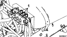
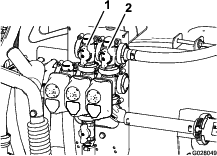
Turn off the left boom and adjust the boom-bypass knob (Figure 29) until the pressure reading is at the previously adjusted level (typically 2.75 bar or 40 psi).
Note: The numbered indicators on the bypass knob and needle are for reference only.
-
Turn on the left boom and turn off the right boom.
-
Adjust the right boom-bypass knob (Figure 29) until the pressure reading is at the previously adjusted level (typically 2.75 bar or 40 psi).
-
Turn on the right boom and turn off the center boom.
-
Adjust the center boom-bypass knob (Figure 29) until the pressure reading is at the previously adjusted level (typically 2.75 bar or 40 psi).
-
Turn all the booms off.
-
Turn the pump off.
Note: Calibration is now complete.
Agitation-Bypass Valve Knob Position
-
The agitation-bypass valve is in the full Open position as shown in A of Figure 30.
-
The agitation-bypass valve is in the Close (0) position as shown in B of Figure 30.
-
The agitation-bypass valve is in an intermediate (adjusted relative to the pressure gauge for the sprayer system) position as shown in C of Figure 30.
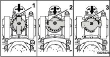
Calibrating the Agitation-Bypass Valve
Select an open flat area to perform this procedure.
-
Fill the spray tank with clean water.
-
Verify the agitation-control valve is open. If it has been adjusted, open it completely at this time.
-
Set the parking brake and start the engine.
-
Set the range selector to NEUTRAL.
-
Set the pump switch to the ON position.
-
Press the accelerator pedal to achieve maximum engine speed and set the throttle lock.
-
Set the 3 boom-section valves to the OFF position.
-
Set the master-boom switch to the ON position.
-
Set the system pressure to MAXIMUM.
-
Press the agitation switch to the OFF position and read the pressure gauge.
-
If the reading remains at 6.9 bar (100 psi) the agitation-bypass valve is properly calibrated.
-
If the pressure gauge reads differently continue to the next step.
-
-
Adjust the agitation-bypass valve (Figure 31) on the backside of the agitation valve until the pressure reading on the gauge is 6.9 bar (100 psi).
-
Press the pump switch to the OFF position, shift the throttle lever to the IDLE position, and turn the ignition switch to the OFF position.
Adjusting the Master-Boom-Bypass Valve
Note: Adjusting the master-boom-bypass valve reduces or increases the amount of flow sent to the agitation nozzles in the tank when the master-boom switch is set to the OFF position.
-
Fill the sprayer tank 1/2 full with clean water.
-
Move the machine to an open level surface.
-
Set the parking brake.
-
Set the range selector to the NEUTRAL position.
-
Set the pump switch to the ON position.
-
Set the agitation switch to the ON position.
-
Set the master-boom switch to the OFF position.
-
Increase the engine speed to full throttle and set the throttle lock to the ON position.
-
Adjust the master-boom-bypass handle to control the amount of agitation occurring in the tank (Figure 31).
-
Reduce the throttle speed to idle.
-
Set the agitation switch and pump switch to the OFF position.
-
Shut off the machine.
Locating the Pump
The pump is located under the seat (Figure 32).
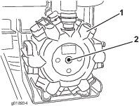
Towing the Sprayer
In case of an emergency, you can tow the sprayer for a short distance. However, we do not recommend this as a standard procedure.
Warning
Towing at excessive speeds could cause a loss of steering control, resulting in personal injury.
Never tow the sprayer faster than 8 km/h (5 mph).
Towing the sprayer is a 2–person job. If you must move the machine a considerable distance, transport it on a truck or trailer; refer to Transporting the Sprayer.
-
Attach a tow line to the frame.
-
Put the range selector in the NEUTRAL position and release the parking brake.
-
Tow the sprayer at less than 8 km/h (5 mph).
Transporting the Sprayer
For moving the sprayer long distances, use a trailer. Secure the sprayer to the trailer. Also, make sure that the booms are tied down and secure. There is 1 metal loop on the front of the frame and 2 loops on the rear of the frame (Figure 33).
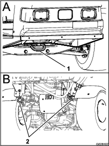
Maintenance
Note: Download a free copy of the schematic by visiting www.Toro.com and searching for your machine from the Manuals link on the home page.For additional information about the sprayer system, refer to Figure 58 in Sprayer Flow Diagram.
Note: Determine the left and right sides of the machine from the normal operating position.
Recommended Maintenance Schedule(s)
| Maintenance Service Interval | Maintenance Procedure |
|---|---|
| After the first 8 hours |
|
| After the first 50 hours |
|
| Before each use or daily |
|
| Every 50 hours |
|
| Every 100 hours |
|
| Every 200 hours |
|
| Every 400 hours |
|
| Every 800 hours |
|
| Yearly |
|
Important: Refer to your engine owner's manual for additional maintenance procedures.
Notation for Areas of Concern
| Inspection performed by: | ||
| Item | Date | Information |
| 1 | ||
| 2 | ||
| 3 | ||
| 4 | ||
| 5 | ||
| 6 | ||
| 7 | ||
| 8 | ||
| 9 | ||
| 10 | ||
| 11 | ||
| 12 | ||
Caution
If you leave the key in the ignition switch, someone could accidently start the engine and seriously injure you or other bystanders.
Remove the key from the ignition and disconnect the wire(s) from the spark plug(s) before you perform any maintenance. Set the wire(s) aside so that it does not accidentally contact the spark plug(s).

Pre-Maintenance Procedures
Raising the Sprayer
Whenever the engine is run for routine maintenance and/or engine diagnostics, the rear wheels of the sprayer should be 2.5 cm (1 inch) off the ground with the rear axle supported on jack stands.
Danger
A sprayer on a jack may be unstable and slip off the jack, injuring anyone beneath it.
-
Do not start the engine while the sprayer is on a jack.
-
Always remove the key from the ignition before getting off the sprayer.
-
Block the tires when the sprayer is on a jack.
The jacking point at the front of the sprayer is under the front crossbar. The jacking point at the rear of the sprayer is on the rear frame support, behind the rear tie-downs (Figure 35).
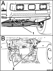
Lubrication
Greasing the Sprayer
| Maintenance Service Interval | Maintenance Procedure |
|---|---|
| Every 50 hours |
|
| Every 100 hours |
|
Grease Type: No. 2 lithium grease
-
Wipe the grease fitting clean so that foreign matter cannot be forced into the bearing or bushing.
-
Pump grease into the bearing or bushing.
-
Wipe off excess grease.
See Figure 34 for the location of all of the grease points.
Greasing the Boom Hinges
| Maintenance Service Interval | Maintenance Procedure |
|---|---|
| Every 100 hours |
|
Important: If the boom hinge is washed with water, you must clear all water and debris from the hinge assembly and you must apply fresh grease.
Grease Type: No. 2 lithium grease
-
Wipe the grease fittings clean so that foreign matter cannot be forced into the bearing or bushing.
-
Pump grease into the bearing or bushing at each fitting Figure 36.
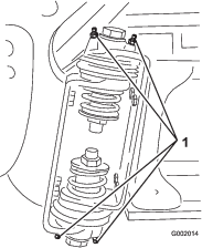
-
Wipe off excess grease.
-
Repeat the procedure for each boom pivot.
Engine Maintenance
Checking the Air-Intake Screen
| Maintenance Service Interval | Maintenance Procedure |
|---|---|
| Before each use or daily |
|
| Every 100 hours |
|
Check and clean as necessary the air-intake screen on the front of the engine before each use or daily.
Servicing the Air Cleaner
| Maintenance Service Interval | Maintenance Procedure |
|---|---|
| Every 50 hours |
|
| Every 200 hours |
|
Removing the Foam and Paper Elements
-
Set the parking brake, stop the pump, shut off the engine, and remove the ignition key.
-
Release the latch on the back of the seat and lift the seat forward.
-
Clean around the air cleaner to prevent dirt from getting into the engine and causing damage (Figure 37).
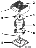
-
Loosen the knob on the air-cleaner cover and remove the cover (Figure 37).
-
Carefully slide the foam element off the paper element (Figure 37).
-
Unscrew the cover nut and remove the cover and paper element (Figure 37).
Cleaning the Foam Element
-
Wash the foam element in liquid soap and warm water.
-
When the element is clean, rinse it thoroughly.
-
Dry the element by squeezing it in a clean cloth.
-
Put 30 to 59 ml (1 to 2 fl oz) of oil on the element (Figure 38).
Important: Replace the foam element if it is torn or worn.
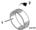
-
Squeeze the element to distribute the oil.
Checking the Paper Element
Inspect the paper element for tears, an oily film, damage to the rubber seal, excessive dirt, or other damage (Figure 39). If any of these conditions exit, replace the filter.
Important: Do not clean the paper element with pressurized air or liquids, such as solvent, gas, or kerosene.
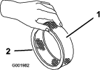
Important: To prevent engine damage, always operate the engine with the complete foam and paper air-cleaner assembly installed.
Installing the Foam and Paper Elements
-
Carefully slide the foam element onto the paper air-cleaner element (Figure 37).
-
Slide the air-cleaner assembly and cover onto the long rod.
-
Install the cover nut finger-tight against the cover (Figure 37).
Note: Ensure that the rubber seal is flat against the air-cleaner base and cover.
-
Install the air-cleaner cover and knob (Figure 37).
-
Close and latch the seat.
Servicing the Engine Oil
Crankcase Capacity is 2.0 L (2.1 US qt) with the filter.
Use high-quality engine oil that meets the following specifications:
-
API classification Level required: SJ or higher.
-
Preferred oil: SAE 10W30 (above 0°F)
-
Alternate oil: SAE 5W30 (below 32°F)
Toro Premium Engine Oil is available from your distributor in either 10W30 or 5W30 viscosity. See the Parts Catalog for part numbers.
Checking the Engine Oil
| Maintenance Service Interval | Maintenance Procedure |
|---|---|
| Before each use or daily |
|
| Every 400 hours |
|
The engine is shipped with oil in the crankcase; however, you must check the level of oil before you first start the engine and after you have run it.
-
Position the machine on a level surface.
-
Remove the dipstick and wipe it with a clean rag (Figure 40). Insert the dipstick into the tube and make sure that it is seated fully. Remove the dipstick and check the oil level.

-
If the oil level is low, remove the filler cap from the valve cover (Figure 40) and pour oil into the opening until the oil level is up to the FULL mark on the dipstick. Add the oil slowly and check the level often during this process. Do not overfill.
-
Install the dipstick firmly in place.
Changing the Engine Oil
| Maintenance Service Interval | Maintenance Procedure |
|---|---|
| After the first 50 hours |
|
| Every 100 hours |
|
-
Start the engine and let it run for 5 minutes. This warms the oil so it drains better.
-
Set the parking brake, stop the pump, shut off the engine, and remove the ignition key.
-
Release the latch on the back of the seat and lift the seat forward.
Caution
Components under the seat are hot if the sprayer has been running. If you touch hot components you may be burned.
Allow the sprayer to cool before performing maintenance or touching components under the hood.
-
Place a pan below the oil drain.
-
Remove the drain plug (Figure 41).
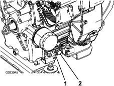
-
When the oil has drained completely, replace the drain plug and torque it to 13.6 N∙m (10 ft-lb).
-
Dispose of the used oil at a certified recycling center.
-
Slowly pour approximately 80% of the specified amount of oil into the oil filler tube (Figure 40).
-
Check the oil level.
-
Slowly add additional oil to bring the oil level to the FULL mark on the dipstick.
Important: Overfilling the crankcase with oil may cause engine damage.
Changing the Engine-Oil Filter
| Maintenance Service Interval | Maintenance Procedure |
|---|---|
| Every 100 hours |
|
-
Drain the oil from the engine; refer to Changing the Engine Oil.
-
Remove the oil filter (Figure 41).
-
Wipe the filter adapter gasket surface.
-
Apply a thin coat of new oil to the rubber gasket on the replacement filter.
-
Install the replacement oil filter to the filter adapter. Turn the oil filter clockwise until the rubber gasket contacts the filter adapter, then tighten the filter an additional 1/2 turn (Figure 41).
-
Fill the crankcase with the correct type of new oil; refer to Changing the Engine Oil, steps 8 through 10.
-
Dispose of the used oil filter at a certified recycling center.
Changing the Spark Plugs
| Maintenance Service Interval | Maintenance Procedure |
|---|---|
| Every 200 hours |
|
Type: Champion RC-12YC (or equivalent)
Air Gap: 0.76 mm ( 0.030 inch)
Make sure that the air gap between the center and side electrodes is correct before installing the spark plugs. Use a spark-plug wrench for removing and installing the spark plugs and a gapping tool/feeler gauge to check and adjust the air gap.
Removing the Spark Plugs
-
Set the parking brake, stop the pump, shut off the engine, and remove the ignition key.
-
Release the latch on the back of the seat and lift the seat forward.
-
Pull the wires off the spark plugs (Figure 42).
-
Clean around the spark plugs to prevent dirt from falling into the engine and potentially causing damage.
-
Remove the spark plugs and metal washers.
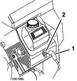
Checking the Spark Plugs
-
Look at the center of the spark plugs (Figure 43).
Note: If you see a light brown or gray coating on the insulator, the engine is operating properly. A black coating on the insulator usually means the air cleaner is dirty.
Important: Do not clean the spark plugs. Always replace a spark plug when it has a black coating, worn electrodes, an oily film, or cracks.
-
Check the gap between the center and side electrodes (Figure 43) and bend the side electrode, if the gap is not correct.
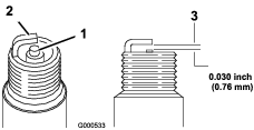
Installing the Spark Plugs
-
Install the spark plugs and metal washers.
-
Tighten the spark plugs to 24.4 to 29.8 N∙m (18 to 22 ft-lb).
-
Push the wires onto the spark plugs (Figure 42).
-
Close and latch the seat.
Fuel System Maintenance
Replacing the Fuel Filter
| Maintenance Service Interval | Maintenance Procedure |
|---|---|
| Every 100 hours |
|
| Every 400 hours |
|
-
Set the parking brake, stop the pump, shut off the engine, and remove the ignition key.
-
Release the latch on the back of the seat and lift the seat forward.
-
Clamp off the hose on either side of the fuel filter to prevent gas from pouring out of the hoses when you remove the filter.
-
Place a drain pan under the filter.
-
Squeeze the ends of the hose clamps together and slide them away from the filter (Figure 44).
-
Remove the filter from the fuel lines.
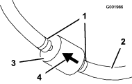
-
Install a new filter and move the hose clamps close to the filter.
Ensure that the flow-direction arrow points toward the engine.
Servicing the Carbon Canister
Checking the Air Filter for the Carbon Canister
| Maintenance Service Interval | Maintenance Procedure |
|---|---|
| After the first 50 hours |
|
| Every 200 hours |
|
Check the opening at the bottom of the air filter for the carbon canister to ensure that it is clean and free of debris and obstructions (Figure 45).
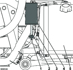
Replacing the Carbon-Canister Filter
| Maintenance Service Interval | Maintenance Procedure |
|---|---|
| After the first 50 hours |
|
| Every 200 hours |
|
-
Remove the barbed fitting of the carbon-canister filter from the hose at the bottom of the carbon canister, and remove the filter (Figure 45).
Note: Discard the old filter.
-
Fully insert the barbed fitting of the new carbon-canister filter into the hose at the bottom of the carbon canister.
Draining the Fuel Tank
| Maintenance Service Interval | Maintenance Procedure |
|---|---|
| Every 400 hours |
|
Drain and clean the fuel tank if the fuel system becomes contaminated or if you plan to store the machine for an extended period. Use fresh, clean fuel to flush out the tank.
-
Transfer the fuel from the tank into an approved fuel container using a siphon pump, or remove the tank from the machine and pour the fuel out of the tank fill spout into the fuel container.
Note: If you remove the fuel tank, you will need to remove the fuel and return hoses from the tank before removing the tank.
-
Replace the fuel filter; refer to Replacing the Fuel Filter.
-
Flush the tank with fresh, clean fuel, if necessary.
-
Install the tank if you removed it.
-
Fill the tank with fresh, clean fuel.
Electrical System Maintenance
Locating the Fuses
There are 2 fuse blocks and 1 empty slot in the electrical system. They are located beneath the seat (Figure 46).
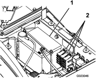
Servicing the Battery
Warning
CALIFORNIA
Proposition 65 Warning
Use of this product may cause exposure to chemicals known to the State of California to cause cancer, birth defects, or other reproductive harm.
Important: Do not jump start the sprayer.
Always keep the battery clean and fully charged. Use a paper towel to clean the battery and battery box. If the battery terminals are corroded, clean them with a solution of 4 parts water and 1 part baking soda. Apply a light coating of grease to the battery terminals to prevent corrosion.
Voltage: 12 V with 280 cold cranking A at 0°F
Removing the Battery
-
Position the sprayer on a level surface, set the parking brake, stop the pump, shut off the engine, and remove the ignition key.
-
The battery is located on the right side of the machine behind the pump (Figure 46).
-
Disconnect the negative (black) ground cable from the battery post.
Warning
Incorrect battery-cable routing could damage the sprayer and cables causing sparks. Sparks can cause the battery gasses to explode, resulting in personal injury.
-
Always disconnect the negative (black) battery cable before disconnecting the positive (red) cable.
-
Always connect the positive (red) battery cable before connecting the negative (black) cable.
Warning
Battery terminals or metal tools could short against metal sprayer components causing sparks. Sparks can cause the battery gasses to explode, resulting in personal injury.
-
When removing or installing the battery, do not allow the battery terminals to touch any metal parts of the sprayer.
-
Do not allow metal tools to short between the battery terminals and metal parts of the sprayer.
-
Always keep the battery strap in place to protect and secure the battery.
-
-
Disconnect the positive (red) cable from the battery post.
-
Remove the battery retainer and fasteners (Figure 46).
-
Remove the battery.
Installing the Battery
| Maintenance Service Interval | Maintenance Procedure |
|---|---|
| Every 50 hours |
|
-
Set the battery on the battery box so that the battery posts are toward the front of the sprayer.
-
Install the battery retainer and secure it with the fasteners you removed previously (Figure 46).
Important: Always keep the battery retainer in place to protect and secure the battery.
-
Connect the positive (red) cable to the positive (+) battery post and the negative (black) cable to the negative (-) battery post using the bolts and wing nuts. Slide the rubber boot over the positive battery post.
-
Install the battery cover and secure it with the 2 knobs (Figure 46).
Checking the Electrolyte Level
| Maintenance Service Interval | Maintenance Procedure |
|---|---|
| Every 50 hours |
|
Note: When the machine is in storage check the battery-electrolyte level every 30 days.
-
Loosen the knobs on the sides of the battery box and remove the battery cover (Figure 46).
-
Remove the filler caps. If the electrolyte is not up to the fill line, add the required amount of distilled water; refer to Adding Water to the Battery.
Danger
Battery electrolyte contains sulfuric acid which is a deadly poison and causes severe burns.
-
Do not drink electrolyte or allow it to contact your skin, eyes or clothing. Wear safety glasses to shield your eyes and rubber gloves to protect your hands.
-
Fill the battery where clean water is always available for flushing the skin.
-
Adding Water to the Battery
The best time to add distilled water to the battery is just before you operate the machine. This lets the water mix thoroughly with the electrolyte solution.
-
Clean the top of the battery with a paper towel.
-
Remove the filler caps from the battery and slowly fill each cell with distilled water until the level is up to the fill line. Replace the filler caps.
Important: Do not overfill the battery. Electrolyte will overflow onto other parts of the sprayer and severe corrosion and deterioration will result.
Charging the Battery
Warning
Charging the battery produces gasses that can explode.
Never smoke near the battery and keep sparks and flames away from battery.
Important: Always keep the battery fully charged (1.260 specific gravity). This is especially important to prevent battery damage when the temperature is below 0°C (32°F).
-
Remove the battery from the chassis; refer to Removing the Battery.
-
Check the electrolyte level; refer to Checking the Electrolyte Level.
-
Connect a 3 to 4 A battery charger to the battery posts. Charge the battery at a rate of 3 to 4 A for 4 to 8 hours (12 V).
Important: Do not overcharge the battery.
-
Install the battery in the chassis; refer to Installing the Battery.
Storing the Battery
If the machine will be stored for more than 30 days, remove the battery and charge it fully. Either store it on the shelf or on the machine. Leave the cables disconnected if it is stored on the machine. Store the battery in a cool atmosphere to avoid quick deterioration of the charge in the battery. To prevent the battery from freezing, make sure that it is fully charged.
Drive System Maintenance
Inspecting the Wheels and Tires
| Maintenance Service Interval | Maintenance Procedure |
|---|---|
| After the first 8 hours |
|
| Before each use or daily |
|
| Every 100 hours |
|
Check the tire pressure every 8 hours or daily to ensure proper levels. Fill the tires to 138 kPa (20 psi). Also, check the tires for wear or damage.
Check the wheels to ensure that they are mounted securely after the first 8 operating hours and then every 100 hours thereafter. Torque the front and rear lug nuts to 102 to 108 N∙m (75 to 80 ft-lb).
Check the tire condition at least every 100 hours of operation. Operating accidents, such as hitting curbs, can damage a tire or rim and also disrupt wheel alignment, so inspect the tire condition after an accident.
Adjusting Differential-lock Cable
| Maintenance Service Interval | Maintenance Procedure |
|---|---|
| Every 200 hours |
|
-
Move the differential-lock lever to the OFF position.
-
Loosen the jam nuts securing the differential-lock cable to the bracket on the transaxle (Figure 47).
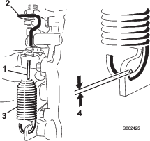
-
Adjust the jam nuts to obtain a 0.25 to 1.5 mm (0.01 to 0.06 inch) gap between the spring hook and the OD of the hole in the transaxle lever.
-
Tighten the jam nuts when finished.
Adjusting the Front Wheel Toe-in
| Maintenance Service Interval | Maintenance Procedure |
|---|---|
| Every 100 hours |
|
The toe-in should be 0 to 6 mm (0 to 1/4 inch).
-
Fill the tank with approximately 331 L (87.5 US gallons) of water.
-
Check and fill all tires; refer to Checking the Tire Pressure.
-
Drive the sprayer back and forth a few times to relax the A-arms, then drive it forward at least 3 m (10 ft).
-
Measure the distance between both of the front tires at the axle height at both the front and rear of the front tires (Figure 48).
Note: A fixture or alignment gauge is needed for the rear measurement of the front tires at axle height. Use the same fixture or alignment gauge to accurately measure the front of the front tires at axle height (Figure 48).
The front of the tires should be 0 to 6 mm (0 to 1/4 inch) closer than the back side of the front tires.
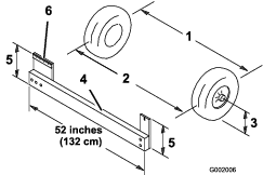
-
If the measurement does not fall within the specified range, loosen the jam nuts at both ends of the tie rods (Figure 49).

-
Rotate both tie rods to move the front of the tire inward or outward.
Note: The tie rods should be the same length when you are finished.
-
Tighten the tie rod jam nuts when the adjustment is correct.
-
Ensure that there is full travel of the steering wheel in both directions.
Brake Maintenance
Checking the Brake Fluid
The brake-fluid reservoir is shipped from the factory filled with DOT 3 brake fluid. Check the level before starting the engine each day.
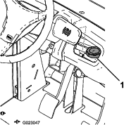
-
Position the sprayer on a level surface, set the parking brake, stop the pump, shut off the engine, and remove the ignition key.
-
The fluid level should be up to the FULL line on the reservoir.
-
If the fluid level is low, clean the area around the reservoir cap, remove the cap, and fill the reservoir to the proper level. Do not overfill.
Inspecting the Brakes
| Maintenance Service Interval | Maintenance Procedure |
|---|---|
| Every 100 hours |
|
The brakes are a critical safety component of the sprayer. Inspect them as follows:
-
Inspect the brake shoes for wear or damage. If the lining (brake pad) thickness is less than 1.6 mm (1/16 inch), replace the brake shoes.
-
Inspect the backing plate and other components for signs of excessive wear or deformation. If any deformation is found, replace the appropriate components.
Adjusting the Parking Brake
| Maintenance Service Interval | Maintenance Procedure |
|---|---|
| Every 200 hours |
|
-
Remove the plastic grip.
-
Loosen the set screw securing the knob to the parking-brake lever (Figure 51).

-
Rotate the knob until a force of 18 to 23 kg (40 to 50 lb) is required to actuate lever.
-
Tighten the set screw.
Hydraulic System Maintenance
Checking the Transaxle/Hydraulic Fluid
| Maintenance Service Interval | Maintenance Procedure |
|---|---|
| Every 200 hours |
|
-
Position the sprayer on a level surface, set the parking brake, stop the pump, shut off the engine, and remove the ignition key.
-
Remove the transaxle dipstick and wipe it with a clean rag (Figure 52).
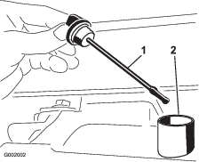
Important: Be very careful not to get dirt or other contaminants into the opening when checking the transmission oil.
-
Insert the dipstick into the tube and make sure that it is seated fully. Remove the dipstick and check the oil level.
-
The transaxle fluid level should be at the top of the flat portion of the dipstick. If it is not, fill the reservoir with the appropriate fluid; refer to Changing Transaxle/Hydraulic Fluid.
-
Install the dipstick firmly in place.
Changing Transaxle/Hydraulic Fluid
| Maintenance Service Interval | Maintenance Procedure |
|---|---|
| Every 800 hours |
|
-
Position the sprayer on a level surface, set the parking brake, stop the pump, shut off the engine, and remove the ignition key.
-
Place a drain pan under the drain plug of the reservoir.
-
Remove the drain plug from the side of the reservoir, and let the hydraulic fluid flow into the drain pan (Figure 53).
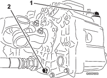
-
Note the orientation of the hydraulic hose and 90° fitting connected to the strainer.
-
Remove the hydraulic hose and 90° fitting (Figure 54).
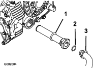
-
Remove the strainer and clean it by back flushing it with a clean degreaser.
-
Allow the strainer to air dry.
-
Install the strainer when the oil is draining.
-
Install the hydraulic hose and 90° fitting to the strainer.
-
Install and tighten the drain plug.
-
Fill the reservoir with approximately 7 L (7.5 US qt) of Dexron III ATF.
Important: Use only the hydraulic fluids specified. Other fluids could cause system damage.
-
Start the engine and drive the sprayer to fill the hydraulic system.
-
Check the oil level and replenish it, if required.
Replacing the Hydraulic Filter
| Maintenance Service Interval | Maintenance Procedure |
|---|---|
| After the first 8 hours |
|
| Every 800 hours |
|
Use the Toro replacement filter (Part No. 54-0110).
Important: Use of any other filter may void the warranty on some components.
-
Position the sprayer on a level surface, set the parking brake, stop the pump, shut off the engine, and remove the ignition key.
-
Clean the area around the filter mounting area.
-
Place a drain pan under the filter.
-
Remove the filter (Figure 55).
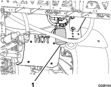
-
Lubricate the new filter gasket.
-
Ensure that the filter mounting area is clean.
-
Screw the filter on until the gasket contacts the mounting plate, then tighten the filter 1/2 turn.
-
Start the engine and let it run for about 2 minutes to purge air from the system.
-
Shut off the engine and check the hydraulic-oil level and for leaks.
Spray System Maintenance
Warning
Chemical substances used in the spray system may be hazardous and toxic to you, bystanders, animals, plants, soils or other property.
-
Carefully read and follow the chemical warning labels and Material Safety Data Sheets (MSDS) for all chemicals used and protect yourself according to the chemical manufacturer's recommendations. For example, use appropriate Personal Protective Equipment (PPE), including face and eye protection, gloves, or other equipment to guard against personal contact with chemicals.
-
Keep in mind that there may be more than 1 chemical used and information on each should be assessed.
-
Refuse to operate or work on the sprayer if this information is not available.
-
Before working on a spray system make sure that the system has been triple rinsed and neutralized according to the recommendations of the chemical manufacturer(s) and all of the valves have been cycled 3 times.
-
Verify that there is an adequate supply of clean water and soap nearby, and immediately wash off any chemicals that contact you.
Inspecting the Hoses
| Maintenance Service Interval | Maintenance Procedure |
|---|---|
| Every 200 hours |
|
Examine each hose in the spray system for cracks, leaks or other damage. At the same time, inspect the connections and fittings for similar damage. Replace any hoses and fittings if damaged.
Changing the Pressure Filter
| Maintenance Service Interval | Maintenance Procedure |
|---|---|
| Every 400 hours |
|
-
Move the machine to a level surface, shut off the sprayer pump, shut off the engine, and remove the key.
-
Align a drain pan under the pressure filter (Figure 56).
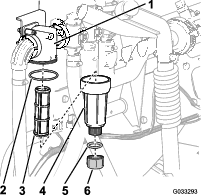
-
Rotate the drain plug counterclockwise and remove it from the bowl of the pressure filter (Figure 56).
Note: Allow the bowl to drain completely.
-
Rotate the bowl counterclockwise and remove from its filter head (Figure 56).
-
Remove the old pressure filter element (Figure 56).
Note: Discard the old filter.
-
Check the O-ring for the drain plug (located inside the bowl) and the O-ring for bowl (located inside the filter head) for damage and wear (Figure 56).
Note: Replace any damaged or worn O-rings for the plug, bowl, or both.
-
Install the new pressure filter element into the filter head (Figure 56).
Note: Ensure that the filter element is firmly seated into the filter head.
-
Install the bowl onto the filter head hand-tight (Figure 56).
-
Install the plug into the bowl hand-tight (Figure 56).
Inspecting the Pump
| Maintenance Service Interval | Maintenance Procedure |
|---|---|
| Every 400 hours |
|
Note: The following machine components are considered parts subject to consumption through use unless found defective and are not covered by the warranty associated with this machine.
Have an Authorized Toro Service Distributor check following internal pump components for damage:
-
Pump diaphragms
-
Pump check valves assemblies
Replace any components, if necessary.
Inspecting the Nylon Pivot Bushings
| Maintenance Service Interval | Maintenance Procedure |
|---|---|
| Every 400 hours |
|
-
Position the sprayer on a level surface, set the parking brake, stop the pump, shut off the engine, and remove the ignition key.
-
Extend the booms to the SPRAY position and support the booms using stands or straps from a lift.
-
With the weight of the boom supported, remove the bolt and nut securing the pivot pin to the boom assembly (Figure 57).
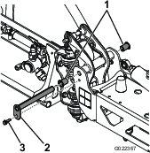
-
Remove the pivot pin.
-
Remove the boom and pivot bracket assembly from the center frame to access the nylon bushings.
-
Remove and inspect the nylon bushings from the front and back sides of the pivot bracket (Figure 57).
Note: Replace any damaged bushings.
-
Place a small amount of oil on the nylon bushings and install them into pivot bracket.
-
Install the boom and pivot bracket assembly into the center frame, aligning the openings (Figure 57).
-
Install the pivot pin and secure it with the bolt and nut removed previously.
-
Repeat the procedure for each boom.
Sprayer Flow Diagram
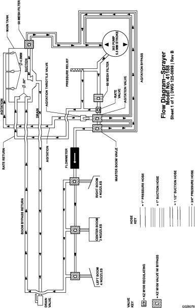
Cleaning
Cleaning the Flowmeter
| Maintenance Service Interval | Maintenance Procedure |
|---|---|
| Every 200 hours |
|
-
Thoroughly rinse and drain the entire spraying system.
-
Remove the flowmeter from the sprayer, and flush it with clean water.
-
Remove the retainer ring on the upstream side (Figure 59).
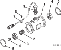
-
Clean the turbine and the turbine hub to remove metal filings and any wettable powders.
-
Inspect the turbine blades for wear.
Note: Hold the turbine in your hand and spin it. It should spin freely with very little drag. If it does not, replace it.
-
Assemble the flowmeter.
-
Use a low-pressure air jet, 50 kPa (5 psi), to ensure that the turbine spins freely. If it does not, loosen the hex stud on the bottom of the turbine hub by 1/16 of a turn until the turbine spins freely.
Cleaning the Suction Strainer
| Maintenance Service Interval | Maintenance Procedure |
|---|---|
| Before each use or daily |
|
-
Remove the retainer from the red fitting attached to the large hose on the top of the tank.
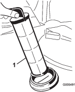
-
Disconnect the hose from the tank.
-
Pull the strainer out of the hole.
-
Clean the strainer with clean running water.
-
Replace the strainer, seating it fully into the hole.
-
Connect the hose to the top of the tank and secure it with the retainer.
Cleaning the Sprayer Valves
-
To clean the rate-control valve, refer to the following sections:
-
To clean the agitation valve; refer to the following sections:
-
To clean the master-boom valve, refer to the following sections:
-
To clean the 3 section valves; refer to the following sections:
Removing the Valve Actuator
-
Position the sprayer on a level surface, set the parking brake, stop the pump, shut off the engine, and remove the key.
-
Remove the 3-pin connector of the valve actuator from the 3 socket electrical connector of the sprayer harness.
-
Remove the retainer that secures the a actuator to the manifold valve for the rate control, agitation, master boom, or boom-section valve (Figure 61).
Note: Squeeze the 2 legs of the retainer together while pushing it down.
Note: Retain the actuator and retainer for installation in Installing the Valve Actuator.
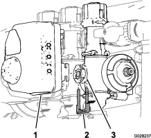
-
Remove the actuator from the manifold valve.
Removing the Rate-Control-Manifold Valve
-
Remove the clamps and gaskets that secure the manifold for the rate-control valve (Figure 62).
Note: Retain the clamp(s) and gasket(s)for installation in Installing the Agitation-Manifold Valve.
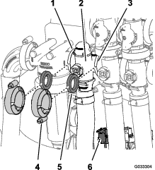
-
Remove the retainer that secures the outlet fitting to the manifold for the rate-control valve (Figure 63).
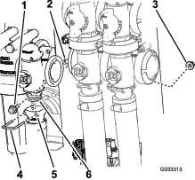
-
Remove the 2 flanged-head bolts and 2 flanged locknuts that secures the rate-control valve to the valve mount and remove the valve manifold from the machine (Figure 63).
Note: If necessary, loosened the mounting hardware for the pressure-filter head to ease removal of the rate-control valve.
Removing the Agitation-Manifold Valve
-
Remove the clamps and gaskets that secure the manifold for the agitation valve (Figure 64) to the agitation-bypass valve, rate-control valve, master-boom valve, and adapter fitting (agitation-throttle valve).
Note: Retain the clamp(s) and gasket(s)for installation in Removing the Agitation-Manifold Valve.
-
Remove the retainer that secures the outlet fitting to the manifold for the agitation valve (Figure 64).
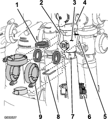
-
Remove the flanged-head bolt and flanged locknut that secures the agitation valve to the valve mount and remove the valve manifold from the machine (Figure 65).
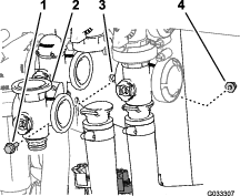
Removing the Master-Boom-Manifold Valve
-
Remove the clamps and gaskets that secure the manifold for the master-boom valve (Figure 66) to the master-boom-bypass valve, agitation valve, and master-boom-manifold valve (at the end of the hose for the flow meter).
Note: Retain the clamp(s) and gasket(s)for installation in Installing the Master-Boom-Manifold Valve.
-
Remove the retainer that secures the outlet fitting to the manifold for the master-boom valve (Figure 66).
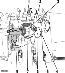
-
Remove the flanged-head bolt and flanged locknut that secures the master-boom valve to the valve mount and remove the valve manifold from the machine (Figure 67).
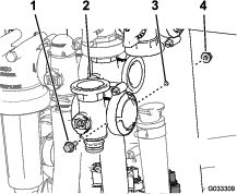
Removing the Section-Manifold Valve
-
Remove clamps and gaskets that secure the manifold for the section valve (Figure 68) to the adjacent section valve (if left section valve, and the reducer coupling).
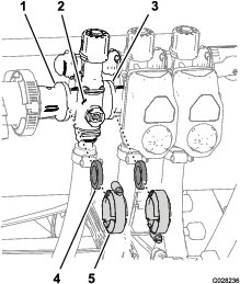
-
Remove the retainers that secure the outlet fitting to the section-valve manifold and the valve manifold to the bypass fitting (Figure 69).
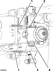
-
For the left or right boom section valves, remove the flanged-head bolts and flanged locknuts that secures the section valve(s) to the valve mount and remove the valve manifold(s) from the machine; for the center section valve, remove the section-valve manifold from the machine (Figure 70).
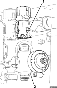
Cleaning the Manifold Valve
-
Position the valve stem so that it is in the closed position (B of Figure 71).
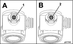
-
Remove the 2 end-cap-fitting assembly from each end of the manifold body (Figure 72 and Figure 73).
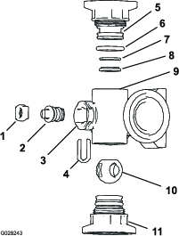
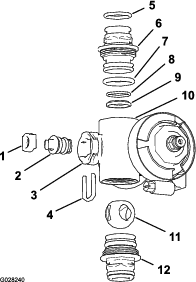
-
Turn the valve stem so that the ball is in the open position (A of Figure 71).
Note: The valve stem should be parallel with the valve flow and the ball should slide out.
-
Remove the stem retainer from the slots in the stem port in the manifold (Figure 72 and Figure 73).
-
Remove the stem retainer and valve-stem seat from the manifold (Figure 72 and Figure 73).
-
Reach into the manifold body and remove the valve-stem assembly (Figure 72 and Figure 73).
-
Clean the inside of the manifold and exterior of the ball valve, valve-stem assembly, stem capture, and end fittings.
Assembling the Manifold Valve
-
Check the condition of the outlet-fitting O-rings (section-valve manifold only), end-cap O-rings, back seating O-rings, ball seat for damage or wear (Figure 72 and Figure 73).
Note: Replace any damaged or worn O-rings or seats.
-
Apply grease to the valve stem and insert it into the valve-stem seat (Figure 72 and Figure 73).
-
Install the valve stem and seat into the manifold and secure the stem and seat with the stem retainer (Figure 72 and Figure 73).
-
Ensure that the back seating O-ring and the ball seat are aligned and seated into the end-cap fitting (Figure 72 and Figure 73).
-
Install the end-cap-fitting assembly onto the manifold body until the flange of the end-cap fitting touches the manifold body (Figure 72 and Figure 73), then turn the end-cap fitting an additional 1/8 to 1/4 turn; torque the fitting to 225 to 282 N∙cm (20 to 25 in-lb).
Note: Use caution so as not to damage the end of the fitting.
-
Insert the ball into the valve body (Figure 74).
Note: The valve stem should fit inside the ball drive slot. If the valve stem does not fit, adjust the position of the ball (Figure 74).
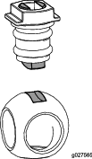
-
Turn the valve-stem assembly so that the valve is closed (B of Figure 71)
-
Repeat steps 4 and 5 for the other end-cap-fitting assembly.
Installing the Rate-Control-Manifold Valve
-
Align a gasket between the flanges of the rate-control-valve manifold and the pressure-filter head (A of Figure 75).
Note: If needed, loosen the mounting hardware for the pressure-filter head as needed to provide clearance.
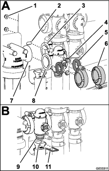
-
Assemble the rate-control-valve manifold, gasket, and pressure-filter head with a clamp tightened hand-tight (A of Figure 75).
-
Align a gasket between the flanges of the rate-control valve and the agitation-valve manifold (A of Figure 75)
-
Assemble the rate-control-valve manifold, gasket, and agitation-valve manifold with a clamp tightened hand-tight (A of Figure 75).
-
Assemble the rate-control valve to the valve mount with the 2 flanged-head bolts and 2 flanged locknuts (A of Figure 75) that you removed in step 3 of Removing the Rate-Control-Manifold Valve and torque the nut and bolt to 1,017 to 1,243 N∙cm (90 to 110 in-lb).
-
Assemble the outlet fitting onto the lower end-cap fitting of the manifold valve (B of Figure 75).
-
Secure the end-cap fitting to the outlet fitting by inserting a retainer into the socket of the outlet fitting (B of Figure 75).
-
If you loosened the mounting hardware for the pressure-filter head, tighten the nut and bolt to 1,978 to 2,542 N∙cm (175 to 225 in-lb).
Installing the Agitation-Manifold Valve
-
Align the flange of the agitation-valve manifold, 1 gasket, and the flange of the agitation-bypass valve (A of Figure 76).
Note: If needed, loosen the mounting hardware for the master-boom valve as needed to provide clearance.
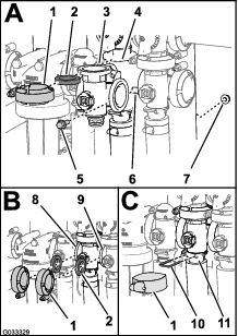
-
Assemble the agitation-bypass valve, gasket, and agitation-valve manifold with a clamp tightened hand-tight (A of Figure 76).
-
Align a gasket between the flanges of the rate-control valve and the agitation-valve manifold (B of Figure 76).
-
Assemble the gasket and agitation-valve manifold with a clamp tightened hand-tight ( B of Figure 76).
-
Align a gasket between the flanges of the agitation-valve manifold and the master-boom valve (B of Figure 76).
-
Assemble the agitation-valve manifold, gasket, and master-boom valve with a clamp tightened hand-tight (B of Figure 76).
-
Assemble the agitation-valve manifold and socket with a clamp tightened hand-tight (C of Figure 76).
-
Secure the end-cap fitting to the outlet fitting by inserting a retainer into the socket of the outlet fitting (C of Figure 76).
-
Assemble the agitation valve to the valve mount with the flanged-head bolt and flanged locknut that you removed in step 3 of Removing the Agitation-Manifold Valve and torque the nut and bolt to 1,017 to 1,243 N∙cm (90 to 110 in-lb).
-
If you loosened the mounting hardware for the master-boom valve, tighten the nut and bolt to 1,978 to 2,542 N∙cm (175 to 225 in-lb).
Installing the Master-Boom-Manifold Valve
-
Align the flange of the master-boom-valve manifold, 1 gasket, and the flange of the master-boom-bypass valve (A of Figure 77).
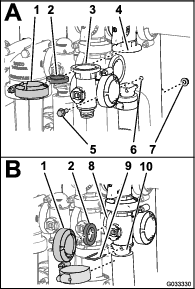
-
Assemble the master-boom-valve manifold, gasket, and master-boom-bypass valve with a clamp tightened hand-tight (A of Figure 77).
-
Align the flange of the master-boom-valve manifold, a gasket, and the agitation-valve manifold (B of Figure 77).
-
Assemble the master-boom-valve manifold, gasket, and agitation-valve manifold with a clamp tightened hand-tight (B of Figure 77)
-
Align the flange of the master-boom-valve manifold, a gasket, and the master-boom house (B of Figure 77).
-
Assemble the master-boom-valve manifold and socket with a clamp tightened hand-tight (B of Figure 77).
-
Secure the end-cap fitting to the outlet fitting by inserting a retainer into the outlet fitting (B of Figure 77).
-
Assemble the agitation valve to the valve mount with the flanged-head bolt and flanged locknut that you removed in step 3 of Removing the Master-Boom-Manifold Valve and torque the nut and bolt to 1,017 to 1,243 N∙cm (90 to 110 in-lb).
Installing the Section-Manifold Valve
-
Insert the upper end-cap fitting of the manifold valve into the bypass fitting (A of Figure 78).
Note: If needed, loosen the mounting hardware for the bypass fitting as needed to provide clearance.
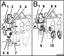
-
Secure the end-cap fitting to the bypass fitting by inserting a retainer into the socket of the bypass fitting (A of Figure 78).
-
Assemble the outlet fitting onto the lower end-cap fitting of the manifold valve (A of Figure 78).
-
Secure the end-cap fitting to the outlet fitting by inserting a retainer into the socket of the outlet fitting (A of Figure 78).
-
Align a 1 gasket between the flanges of the reducer coupling and the section-valve manifold (B of Figure 78).
-
Assemble the reducer coupling, gasket, and section-valve manifold with a clamp tightened hand-tight (B of Figure 78).
-
If installing the 2 left most section valves, align a 1 gasket between the flanges of the 2 adjacent section-valve manifolds (B of Figure 78).
-
Assemble the and 2 adjacent section-valve manifolds and gasket with a clamp tightened hand-tight (B of Figure 78).
-
For the left or right boom-section valves, assemble the valves to the valve mount with the flanged-head bolt and flanged locknut that you removed in step 3 of Removing the Section-Manifold Valve and torque the nuts and bolts to 1,017 to 1,243 N∙cm (90 to 110 in-lb).
-
If you loosened the mounting hardware for the bypass fitting, tighten the nut and bolt to 1,017 to 1,243 N∙cm (90 to 110 in-lb).
Installing the Valve Actuator
-
Align the actuator to the manifold valve and (Figure 61).
-
Secure the actuator and valve with the retainer that you removed in step 3 of Removing the Valve Actuator.
-
Connect the 3-pin connector of the valve-actuator harness to the 3-socket connector of the wire harness of the sprayer
Storage
-
Position the sprayer on a level surface, set the parking brake, stop the pump, shut off the engine, and remove the ignition key.
-
Clean dirt and grime from the entire machine, including the outside of the engine cylinder head fins and blower housing.
Important: You can wash the machine with mild detergent and water. Do not use high-pressure water to wash the machine. Pressure washing may damage the electrical system or wash away necessary grease at friction points. Avoid excessive use of water, especially near the control panel, lights, engine, and the battery.
-
Clean the spray system; refer to the .
-
Clean the pistons in the valve assembly; refer to Cleaning the Sprayer Valves.
-
Condition the sprayer system as follows:
-
Drain the fresh-water tank.
-
Drain the spray system as completely as possible.
-
Prepare rust inhibiting, non-alcohol based, RV antifreeze solution per the manufacturer's instructions.
-
Add the RV antifreeze solution to the fresh-water tank and the sprayer tank.
-
Run the sprayer pump for a few minutes to circulate the RV antifreeze throughout the sprayer system and any installed spray accessories.
-
Drain the fresh-water tank and spray system as completely as possible.
-
-
Use the boom lift switches to raise the booms. Raise the booms until they have moved completely into boom-transport cradle forming the ‘X’ transport position and the boom cylinders are fully retracted. Make sure that the boom cylinders are fully retracted to prevent actuator rod damage.
-
Inspect the brakes; refer to Inspecting the Brakes.
-
Service the air cleaner; refer to Servicing the Air Cleaner.
-
Grease the sprayer; refer to the Lubrication.
-
Change the crankcase oil; refer to Changing the Engine Oil.
-
Check the tire pressure; refer to Checking the Tire Pressure.
-
For storage over 30 days, prepare the fuel system as follows:
-
Add a petroleum based stabilizer/conditioner to fuel in the tank.
Follow mixing instructions from stabilizer manufacturer. Do not use an alcohol based stabilizer (ethanol or methanol).
Note: A fuel stabilizer/conditioner is most effective when mixed with fresh gasoline and used at all times.
-
Run the engine to distribute conditioned fuel through the fuel system (5 minutes).
-
Shut off the engine, allow it to cool, and drain the fuel tank.
-
Start the engine and run it until it stops.
-
Choke the engine.
-
Start and run the engine until it will not start again.
-
Dispose of fuel properly. Recycle as per local codes.
Important: Do not store stabilizer/conditioned gasoline over 90 days.
-
-
Remove the spark plugs and check their condition; refer to Changing the Spark Plugs.
-
With the spark plugs removed from the engine, pour 2 tablespoons of engine oil into the spark plug hole.
-
Use the electric starter to crank the engine and distribute the oil inside the cylinder.
-
Install the spark plugs and tighten to recommended torque; refer to Installing the Spark Plugs.
Note: Do not install the wire on the spark plug(s).
-
Remove the battery from the chassis, check the electrolyte level, and charge it fully; refer to Removing the Battery.
Note: Do not connect the battery cables to the battery posts during storage.
Important: The battery must be fully charged to prevent it from freezing and being damaged at temperatures below 0°C (32°F). A fully charged battery maintains its charge for about 50 days at temperatures lower than 4°C (40°F). If the temperatures will be above 4°C (40°F), check the water level in the battery and charge it every 30 days.
-
Check and tighten all bolts, nuts, and screws. Repair or replace any part that is damaged.
-
Check the condition of all spray hoses, replacing any that are damaged or worn.
-
Tighten all hose fittings.
-
Paint all scratched or bare metal surfaces. Paint is available from your Authorized Service Dealer.
-
Store the machine in a clean, dry garage or storage area.
-
Remove the ignition key and put it in a safe place out of the reach of children.
-
Cover the machine to protect it and keep it clean.
Troubleshooting
| Problem | Possible Cause | Corrective Action |
|---|---|---|
| The starter does not crank. |
|
|
| The engine cranks but does not start. |
|
|
| The engine starts but does not keep running. |
|
|
| The engine runs but knocks or misses. |
|
|
| The engine does not idle. |
|
|
| The engine overheats. |
|
|
| The engine loses power. |
|
|
| There is abnormal vibration or noise. |
|
|
| The machine does not operate or is sluggish in either direction because the engine bogs down or stalls. |
|
|
| The machine does not operate in either direction. |
|
|
| Problem | Possible Cause | Corrective Action |
|---|---|---|
| A boom section does not spray. |
|
|
| A boom section does not turn off. |
|
|
| A boom valve is leaking. |
|
|
| A pressure drop occurs when you turn on a boom. |
|
|
