| Maintenance Service Interval | Maintenance Procedure |
|---|---|
| After the first 10 hours |
|
| Every 200 hours |
|
Introduction
This machine is intended to be used by professional, hired operators in commercial applications. The primary function of the machine is to remove debris from large turf areas. The movable tongue provides an offset position for sweeping.
Read this information carefully to learn how to operate and maintain your product properly and to avoid injury and product damage. You are responsible for operating the product properly and safely.
You may contact Toro directly at www.Toro.com for product safety and operation training materials, accessory information, help finding a dealer, or to register your product.
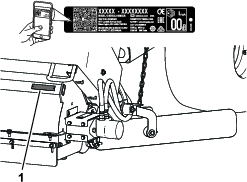
Whenever you need service, genuine Toro parts, or additional information, contact an Authorized Service Dealer or Toro Customer Service and have the model and serial numbers of your product ready. Figure 1 identifies the location of the model and serial numbers on the product. Write the numbers in the space provided.
Important: With your mobile device, you can scan the QR code on the serial number plate (if equipped) [or go to www.Toro.com] to access warranty, parts, and other product information.
This manual identifies potential hazards and has safety messages identified by the safety-alert symbol (Figure 2), which signals a hazard that may cause serious injury or death if you do not follow the recommended precautions.

This manual uses 2 words to highlight information. Important calls attention to special mechanical information and Note emphasizes general information worthy of special attention.
This product complies with all relevant European directives. For details please see the separate product specific Declaration of Conformity (DOC) sheet.
| Electromagnetic Compatibility |
| Domestic: This device complies with FCC Rules Part 15. Operation is subject to the following two conditions: (1) This device may not cause harmful interference and (2) this device must accept any interference that may be received, including interference that may cause undesirable operation. |
| This equipment generates and uses radio frequency energy and if not installed and used properly, in strict accordance with the manufacturer's instructions, may cause interference to radio and television reception. It has been type tested and found to comply within the limits of a FCC Class B computing device in accordance with the specifications in Subpart J of Part 15 of FCC Rules, as stated above. However, there is no guarantee that interference will not occur in a particular installation. If this equipment does cause interference to radio or television reception, which can be determined by turning the equipment off and on, the user is encouraged to try to correct the interference by one or more of the following measures:Reorient the receiving antenna, relocate the remote control receiver with respect to the radio/TV antenna or plug the controller into a different outlet so that the controller and radio/TV are on different branch circuits.If necessary, the user should consult the dealer or an experienced radio/television technician for additional suggestions.The user may find the following booklet prepared by the Federal Communications Commission helpful: "How to Identify and Resolve Radio-TV Interference Problems". This booklet is available from the U.S. Government Printing Office, Washington, DC 20402. Stock No. 004-000-00345-4. |
| FCC ID: W7OMRF24J40MDME-Base, OA3MRF24J40MA-Hand Held |
| IC: 7693A-24J40MDME-Base, 7693A-24J40MA-Hand Held |
| Operation is subject to the following two conditions: (1) this device may not cause interference, and (2) this device must accept any interference, including interference that may cause undesired operation of the device. |
| Japan Electromagnetic Compatibility Certification | |
| Handheld: |  |
| RF2CAN: |  |
| Mexico Electromagnetic Compatibility Certification | |
| Handheld: |  |
| RF2CAN: |  |
| Korea Electromagnetic Compatibility Certification(Decal provided in separate kit) | |
| Handheld: |  |
| RF2CAN: |  |
| Singapore Electromagnetic Compatibility Certification | |
| Handheld: | TWM240007_IDA_N4022-15 |
| RF2CAN: | TWM-240005_IDA_N4024–15 |
| Morocco Electromagnetic Compatibility Certification | |
| AGREE PAR L’ANRT MAROC | |
| Numero d’agrement: | MR 14093 ANRT 2017 |
| Delivre d’agrement: | 29/05/2017 |
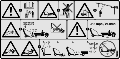
Warning
CALIFORNIA
Proposition 65 Warning
Use of this product may cause exposure to chemicals known to the State of California to cause cancer, birth defects, or other reproductive harm.
Safety
General Safety
This product is capable of causing personal injury. Always follow all safety instructions to avoid serious personal injury.
Using this product for purposes other than its intended use could prove dangerous to you and bystanders.
-
Read and understand the contents of both this Operator’s Manual and the operator’s manual of the tow vehicle before using this machine. Ensure that everyone using this product knows how to use this machine and the tow vehicle and understands the warnings.
-
Use your full attention while operating the machine. Do not engage in any activity that causes distractions; otherwise, injury or property damage may occur.
-
Do not put your hands or feet near moving components of the machine.
-
Do not operate the machine without all guards and other safety protective devices in place and working on the machine.
-
Keep the machine a safe distance away from bystanders while it is moving.
-
Keep children out of the operating area. Never allow children to operate the machine.
-
Stop the machine, shut off the engine, engage the parking brake, remove the key, and wait for all moving parts to stop before servicing, fueling, or unclogging the machine.
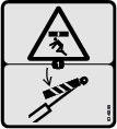
Improperly using or maintaining this machine can result in injury. To reduce the potential for injury, comply with these safety instructions and always pay attention to the safety-alert symbol, which means Caution, Warning, or Danger—personal safety instruction. Failure to comply with these instructions may result in personal injury or death.
You can find additional safety information where needed throughout this manual.
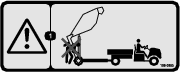
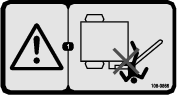
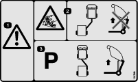
Safety and Instructional Decals
 |
Safety decals and instructions are easily visible to the operator and are located near any area of potential danger. Replace any decal that is damaged or missing. |


Setup
Reviewing the Machine Requirements
-
The machine can be towed by most utility tractors equipped with hydraulics producing 26.5 to 30 L/min (7 to 8 gpm) at 13,790 kPa (2,000 psi) and flotation tires for operation over golf greens. Ensure that the tractor has adequate brakes and a drawbar hitch capacity to handle a 1587 kg (3,500 lb) trailer. Refer to the towing vehicle Operator's Manual for towing instructions and precautions.
-
The Workman vehicle requires the High-Flow Hydraulics Kit. Workman vehicles with serial numbers prior to 900000001 require the Heavy Duty Drawbar (Model 44212 or 44213) installed.
Note: The 4WD Workman model is the best for hilly or bermed approaches to greens.
Important: For older model Workman vehicles, do not attempt to pull the machine when loaded with material, with the standard Workman hitch. It is only rated to 680 kg (1,500 lb) and may bend or damage the cross tube axle support or rear spring shackles. Always use the Drawbar Kit for Heavy-Duty Workman Vehicles (Model 44212) or Hitch Frame and Draw Bar Kit for Heavy-Duty Workman Vehicles (Model 44213).
Important: Do not attempt towing a loaded machine with a light utility vehicle or run-about. These machines do not have adequate brakes, suspension, or frame strength to handle the weight of the machine.
-
Trailer brakes are recommended when using the machine in hilly terrain. When fully loaded, the machine may weigh as much as 1,588 kg (3,500 lb) (GVW). This weight is higher than the recommended towing and braking limit of most utility vehicles. A trailer brake kit is available for direct installation with the Workman vehicle.
Note: The trailer brake kit can be adapted to other vehicles with a 12 V brake light source.
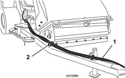
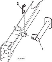
Removing the Hitch Tongue and Hydraulic Cylinder from the Shipping Position
Note: Have 2 people remove the hitch assembly.
-
Remove the pin assembly, bolt and nut securing the hydraulic cylinder and hoses to the hitch tongue for shipping. Also, cut the cable tie. Carefully lower the cylinder and hoses from the tongue. Retain the pin assembly and fasteners for re-use.
-
Remove the hair pin cotter and hitch pin securing the hitch tongue to the upper shipping bracket. The hitch tongue is very heavy, use caution when removing the tongue from the shipping brackets.
-
Pivot at the lower shipping pin and pivot the tongue down.
-
Remove the pin assembly, bolt and nut securing the hitch tongue to the lower shipping bracket.
Note: The machine will shift upward at the lower pin shipping bracket.
-
Remove the fasteners securing the shipping brackets to the machine. Remove and discard the shipping brackets.
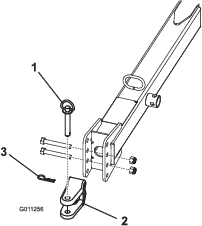
Installing the Hitch Tongue
Parts needed for this procedure:
| Hitch tongue | 1 |
| Hitch pin | 1 |
| Bolt (3/8 x 1-1/4 inch) | 1 |
| Nut (3/8-16) | 1 |
| Large washer | 1 |
| Large nut | 1 |
| Square-head set screw | 1 |
Note: This procedure requires 2 people.
-
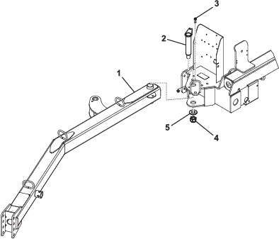
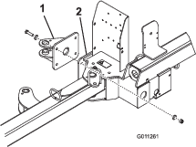
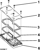
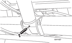
Insert the rear end of the hitch tongue between the mounting plates on the machine while aligning the mounting holes (Figure 3).
Note: The hose guides are to be positioned on top of hitch tongue.
-
Insert the hitch pin through the mounting plates and the hitch tongue (Figure 3).
-
Secure the top of the hitch pin to the mounting plate with a bolt (3/8 x 1-1/4 inch) and a locknut (3/8 inch) as shown in Figure 3.
-
Secure the bottom of the hitch pin with a large washer, large nut, and square-head set screw (Figure 3).
-
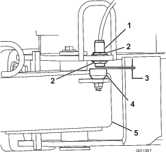
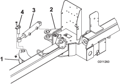
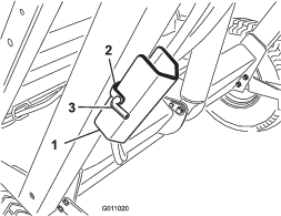
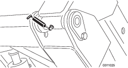
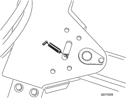
Loosen the jam nuts securing the proximity switch to the frame and lower the switch until it is 2.6 to 4.0 mm (0.10 to 0.16 inch) from the sensing plate on the hitch tongue (Figure 4). Tighten the jam nuts to secure the adjustment.
Installing the Hydraulic Cylinder
Parts needed for this procedure:
| Rear actuator tab | 1 |
| Bolt (1/2 x 2 inch) | 4 |
| Flat washer (0.531 x 0.063 inch) | 8 |
| Locknut (1/2 inch) | 4 |
| Bolt (3/8 x 1-1/4 inch) | 2 |
| Pin assembly | 2 |
| Flange nut (3/8 inch) | 2 |
-
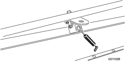
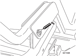
Mount the rear actuator tab to the machine frame with 4 bolts (1/2 x 2 inch), 8 flat washers (0.531 x 0.063), and 4 locknuts (1/2 inch). Position the components as shown in Figure 5.
-
Secure each end of the hydraulic cylinder to an actuator tab with a pin assembly, a bolt (3/8 x 1-1/4 inch), and a flange nut (3/8 inch) Figure 6).
Note: Make sure that the rod end (working end) of the cylinder is attached to the front actuator tab.
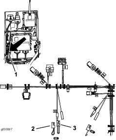
Installing the Power Wire Harness
Parts needed for this procedure:
| Power wire harness | 1 |
| Cable tie | 2 |
| Fuse | 1 |
-
Disconnect the battery from the vehicle.
-
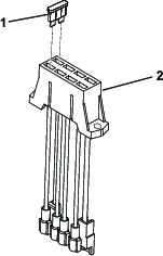
Attach the power wire harness ring terminal to the ground bolt near the vehicle fuse block.
-
Plug the harness wire into the red wire on the back of the fuse block.
Note: If the Workman vehicle does not have an open fuse slot, obtain and install a Toro accessory fuse block (Part No. 92-2641).
-
Insert the 20 A fuse into the slot in the fuse block (Figure 7).
-
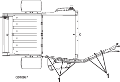
Route the wire harness alongside the main vehicle wire harness to the rear of the vehicle (Figure 8).
-
Secure the wire harness to the vehicle in several places with cable ties. Keep the harness away from any hot or rotating components.
Note: The harness is equipped with a connector for the optional brake control kit.
-
Connect the vehicle battery; refer to the vehicle Operator’s Manual.
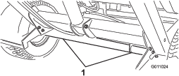
Mounting the Machine to the Towing Vehicle
Parts needed for this procedure:
| Hitch pin | 1 |
| Hairpin cotter | 1 |
For proper debris pickup, make sure that the machine frame is parallel with the ground.
-
Position the machine on a flat, level surface.
-
Back the towing vehicle up to the machine.
-
Remove the spring pin, rotate the jack down, and install the spring pin (Figure 9).
-
Jack up the hitch tongue until it is parallel to the ground.
-
Adjust the machine hitch clevis to the same level as towing-vehicle hitch as follows:
-
Remove the bolts and locknuts securing the hitch clevis (Figure 10) to the hitch tongue.
-
Raise or lower the hitch clevis to the position that is approximately level with the tow-vehicle hitch.
-
Secure the clevis to the hitch with the previously removed bolts and locknuts.
Note: Ensure that the machine is parallel with the ground.
-
-
Connect the machine clevis hitch to the towing-vehicle hitch with the hitch pin and hairpin cotter.
-
Remove the spring pin, rotate the jack up to the storage position, and install the spring pin.
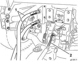
Routing and Securing the Hydraulic Hoses and Wire Harness
Connecting the Hydraulic Hoses
Connect the hydraulic hoses from the machine to the quick couplers on the towing vehicle (Figure 14).
Important: Make sure that the brush rotates in the proper direction (when viewed from the motor end, the brush should rotate clockwise). If the brush is rotating counterclockwise, reverse the hydraulic hose connections.
Note: Mark the high-pressure hose with a cable tie to identify the correct hose installation (Figure 15).

Connecting the Harness
Connect the harness from the machine to the power harness on the towing vehicle (Figure 14).
Note: Ensure that the harness cannot get pinched in the hitch and that it is not on top of or around the hitch pin.
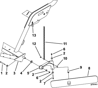
Mounting the Windrow Blades
Parts needed for this procedure:
| Blade-mounting assembly | 1 |
| Bolt (7/16 x 3-1/4 inches) | 2 |
| Small washer (1/2 inch) | 4 |
| Large washer | 1 |
| Spacer | 1 |
| Locknut (7/16 inch) | 2 |
| Chain | 1 |
| Bolt (3/8 x 1-1/4 inches) | 1 |
| Flange nut (3/8 inch) | 1 |
| Snap link | 1 |
-
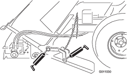
Secure the blade mounting assembly to the left end of the machine frame with a bolt (7/16 x 3-1/4 inches), 2 small washers, a large washer, and a locknut (7/16 inch).
Note: Position components as shown in Figure 16.
-
Secure the windrow blade to the mounting assembly with a bolt (7/16 x 3-1/4 inches), 2 flat washers, a spacer, and a locknut (7/16 inch). Assemble the components as shown in Figure 16.
Note: Position the longer end of the blade away from the machine.
-
Secure the chain to the blade mounting assembly with a bolt (3/8 x 1-1/4 inches) and a flange nut (3/8 inch) (Figure 16).
-
Secure the other end of the chain to the slot in the frame with the snap link (Figure 16).
Note: There should be some slack in the chain when connected.
-
Grease the fitting on the blade mounting assembly and on the windrow blade hub with No. 2 lithium grease.
Note: When the windrow is not required, unhook the chain from the snap link, pivot the windrow assembly upward, and hook the chain at the raised level.
Assembling the Handheld Remote
Parts needed for this procedure:
| Handheld remote | 1 |
| Battery (AAA) | 4 |
| Small screws | 6 |
-
Remove the rubber bands securing the remote halves together, and remove the back cover.
-
Plug each battery into a terminal cradle, observing proper polarity (Figure 17).
Note: If you install the batteries improperly, the machine will not be damaged, but it will fail to operate. The cradle is embossed with polarity markings for each terminal.
-
Ensure that the steel gasket and rubber seal are seated in the channel in the remote and set the back cover in place (Figure 17).
-
Secure the cover with 6 screws (Figure 17) and torque them to 1.5 to 1.7 N∙m (13 to 15 in-lb).
Note: Do not overtighten the screws.
Product Overview
Hopper Dump Button
To dump the hopper, press the hopper dump button 2 times (Figure 18).
Important: The machine must be directly behind the towing vehicle and in transport height before you can activate the dump sequence.
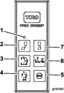
Sweeper Down Button
To lower the hopper, press the sweeper down button (Figure 18). You can lower the hopper when it is at any of the following positions:
-
Hopper dump height
-
Transport height
-
Turn around height
Note: When lowering the hopper from the dump position, you can stop the lower hopper function at any time by releasing the sweeper down button.
Note: With the machine in the transport or turn-around positions, you can stop the lower hopper function by pressing the sweeper up button.
Sweeper Up Button—Standard Mode
To raise the machine in standard mode, press the sweeper-up button. The hopper stops at the pre-defined height (Figure 18).
-
Transport height (home position) is 13-1/4 to 15-1/4 inches.
-
Turn around height (offset position) is 8-1/2 to 10-1/2 inches.
Sweeper Up Button—Optional Mode
This mode allows you to adjust the machine to any desired height and it stops at the pre-defined heights.
Note: Refer to Switching the Sweeper-Up Mode to switch to the optional mode.
To raise the machine in optional mode, press and hold the sweeper-up button until the hopper reaches the desired height or stops at the pre-defined height (Figure 18).
-
Transport height (home position) is 13-1/4 to 15-1/4 inches.
-
Turn around height (offset position) is 8-1/2 to 10-1/2 inches.
Offset Left Button
To offset the machine to the left, press and hold the offset left button (Figure 18). Releasing the button stops the movement to the left.
Offset Right Button
To offset the machine to the right, press and hold the offset right button (Figure 18). Releasing the button stops the movement to the right.
Stop Button
Pressing the stop button disables any active function.
Note: There is approximately a 3-second delay.
Diagnostic Light
The diagnostic light (Figure 19) is located on the front cover and indicates machine fault codes. After you turn the key to the RUN position, the diagnostic light illuminates for 5 seconds, turns off for 5 seconds, and then begins flashing 3 times a second until you push a button on the handheld remote. If the light turns on for 5 seconds and then starts blinking 10 times a second (with or without a 5 second pause), there is a fault with the machine; refer to Checking Fault Codes.
Note: The diagnostic light illuminates when a button is pushed on the handheld remote.
Note: If you have a button pressed on the handheld remote when you start the machine, the light does not flash 3 times a second after it turns off for 5 seconds.
Note: Specifications and design are subject to change without notice.
Dimensions and Weights
| Width | 221 cm (87 inches) |
| Height | 202 cm (79-1/2 inches) |
| Dump height clearance | 173 cm (68 inches) |
| Length | Hopper lowered—173 cm (68 inches) Hopper raised—229 to 249 cm (90 to 98 inches) |
| Empty weight | 680 kg (1,500 lb) |
| Gross vehicle weight (GVW) | 1588 kg (3,500 lb) |
Radio Specifications
| Frequency | 2.4 GHz |
| Max output power | 19.59 dBm |
Attachments/Accessories
A selection of Toro approved attachments and accessories is available for use with the machine to enhance and expand its capabilities. Contact your Authorized Service Dealer or authorized Toro distributor or go to www.Toro.com for a list of all approved attachments and accessories.
To ensure optimum performance and continued safety certification of the machine, use only genuine Toro replacement parts and accessories. Replacement parts and accessories made by other manufacturers could be dangerous, and such use could void the product warranty.
Operation
Note: Determine the left and right sides of the machine from the normal operating position.
Before Operation Safety
-
Never allow children or untrained people to operate or service the machine. Local regulations may restrict the age of the operator. The owner is responsible for training all operators and mechanics.
-
Become familiar with the safe operation of the equipment, operator controls, and safety signs.
-
Know how to stop the machine and shut off the engine of the traction unit quickly.
-
Check that operator-presence controls, safety switches, and shields are attached and functioning properly. Do not operate the machine unless they are functioning properly.
-
Inspect the area where you will use the machine and remove all objects that the machine could strike.
-
When using a Workman machine as a towing vehicle, it is recommended to put 227 kg (500 lb) of weight into the vehicle bed when operating on any slopes.
-
Ensure that your traction unit is suitable for use with an implement of this weight by checking with your traction unit supplier or manufacturer.
-
Shut off the engine and remove the key of the traction unit and wait for all moving parts to stop before making any adjustments to the machine.
Operating the Machine
The primary function of the machine is to sweep up debris from large turf areas.
The machine is operated by using the remote control. Refer to Controls for the proper use of the control buttons.
When transporting and turning, position the machine in the following heights:
-
Transport height (home position) is 33.7 to 38.7 cm (13-1/4 to 15-1/4 inches).
-
Turn around height (offset position) is 21.6 to 26.7 cm (8-1/2 to 10-1/2 inches).
Warning
Rotating parts can cause serious personal injury.
-
Keep your hands, feet, hair, and clothing away from all moving parts to prevent injury.
-
Do not operate the machine with covers, shrouds, or guards removed.
Adjusting the Brush Height
Adjust the machine so that the brush slightly touches the surface but does not penetrate the turf.
Refer to the charts below for the recommended machine settings.
| Condition | Roller/Brush Adjustment | Front Flap Adjustment | Notes |
| Greens/Tee Boxes | 2 to 4 notches from bottom | 6 to 13 mm (1/4 to 1/2 inch) from ground | Brush should be slightly engaged in the turf |
| Fairways | 3 to 5 notches from bottom | 13 to 25 mm (1/2 to 1 inch) from ground | Brush should be engaged into the top 1/3 of the grass height |
| Sports fields | 5 to 7 notches from bottom | 25 to 76 mm (1 to 3 inches) from ground | Brush should be engaged into the top 1/3 of the grass height |
| Leaves | 5 to 9 notches from bottom | Remove front panel | Brush should be engaged into the top 1/3 of the grass height |
| A | B | C | |
| Open Notches | Key Tab Up | Key Tab Down | |
| 0 | 5.500 | 6.000 | |
| 5.625 | 6.125 | ||
| 1 | 5.750 | 6.250 | |
| 5.875 | 6.375 | ||
| 2 | 6.000 | 6.500 | |
| 6.125 | 6.625 | ||
| 3 | 6.250 | 6.750 | |
| 6.375 | 6.875 | ||
| 4 | 6.500 | 7.000 | |
| 6.625 | 7.125 | ||
| 5 | 6.750 | 7.250 | |
| 6.875 | 7.375 | ||
| 6 | 7.000 | 7.500 | |
| 7.125 | 7.625 | ||
| 7 | 7.250 | 7.750 | |
| 7.375 | 7.875 | ||
| 8 | 7.500 | 8.000 | |
| 7.625 | 8.125 | ||
| 9 | 7.750 | 8.250 | |
| 7.875 | 8.375 | ||
| 10 | 8.000 | 8.500 | |
| 8.125 | 8.625 | ||
| 11 | 8.250 | 8.750 | |
| 8.375 | 8.875 | ||
| 12 | 8.500 | 9.000 | |
| 8.625 | 9.125 | ||
| 13 | 8.750 | 9.250 | |
| 8.875 | 9.375 | ||
-
Move the machine to a level surface.
-
Raise the hopper and install the hopper safety support. Refer to Using the Hopper Safety Support.
-
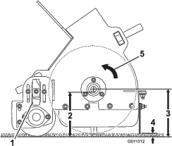
Loosen the locknut on the height adjustment key (Figure 21) so it can be pulled out approximately 13 mm (1/2 inch).

-
Loosen the roller-height adjustment locknuts (Figure 21).
-
Pull out the height-adjusting key and move the rear roller up or down by sliding the roller-height adjusting plate to the desired height (Figure 21).
-
Tighten the locknuts to secure the adjustment.
-
Repeat the procedure on the opposite end of the brush. Ensure that the adjustments are the same.
Adjusting the Roller Scraper
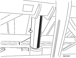
Check and ensure that the roller scraper (Figure 21) is adjusted with a 2 mm (1/16 inch) clearance between the scraper and the roller. Loosen the roller scraper adjusting nuts, position the roller as desired, and tighten the nuts.
Adjusting the Front Flap Height
For best debris pickup results, adjust the front flap (Figure 22) with a 6 mm to 13 mm (1/4 inch to 1/2 inch) clearance between the bottom of the flap and surface.
Note: You may need to raise the front flap all the way or remove the front flap when picking up larger debris or picking up debris in long grass.
-
Loosen the nuts securing the metal strap and the front flap to the brush housing (Figure 23).
-
Adjust the front flap to the desired operating height and tighten the nuts.
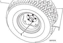
Checking the Tire Pressure
Check the tire pressure daily to ensure that they are inflated properly.
Correct tire air pressure: 86.2 kPa (12.5 psi)
Maximum tire air presssure: 124 kPa (18 psi)
Note: The valve stem is located on the back side of the rim.
Checking the Wheel Lug Nut Torque
Warning
Failure to maintain proper torque could result in failure or loss of wheel and could result in personal injury.
Ensure that the wheel lug nuts are tightened to the appropriate torque.
Check and torque the wheel lug nuts to 95 to 122 N∙m (70 to 90 ft-lb).
Activating the Controller
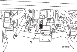
The controller (Figure 25) is activated as soon as you plug the machine harness into the towing-vehicle power harness.
-
On Workman models with serial numbers prior to 899999999, the harness has power.
-
On Workman models with serial numbers 900000001 and up, turn the ignition key to the RUN position to power the harness.
Using the Controller Timeout Feature
The machine is equipped with a timeout feature for the control module. The timeout feature is activated after 2-1/2 hours of continuous remote transmitter inactivity.
-
When in the timeout mode the remote transmitter does not control any function.
-
To wake the controller in timeout mode:
-
On Workman models with serial numbers prior to 899999999, unplug and plug the machine harness into the vehicle power harness.
-
On Workman models with serial numbers 900000001 and up, turn the ignition key to the OFF position and back to the RUN position.
-
-
To avoid controller timeout during operation, use the remote transmitter to offset the machine at least every 2-1/2 hours.
Using the Hopper Safety Support
Whenever you work under the raised hopper, ensure that the hopper safety support is installed onto the extended lift cylinder.
-
Raise the hopper until the lift cylinder is extended.
-
Remove the hairpin cotter and pin securing the safety support to the storage bracket on the machine frame (Figure 26). Remove the safety support.
-
Insert the hopper-safety support onto the cylinder rod, making sure the support end rests against the cylinder barrel and the cylinder-rod end (Figure 27).
Note: Secure the hopper safety support to the cylinder rod with the hair pin cotter and pin.
-
To store the safety support, remove the safety support from the cylinder and secure it to the storage bracket on the machine frame.
-
Always install or remove the safety support from behind the hopper.
Important: Do not try to lower the hopper with the safety support on the cylinder.
During Operation Safety
-
The owner/operator can prevent and is responsible for accidents that may cause personal injury or property damage.
-
Wear appropriate clothing, including eye protection; slip-resistant, substantial footwear; long pants; and hearing protection. Tie back long hair and do not wear loose jewelry.
-
Do not operate the machine when tired, ill, or under the influence of alcohol or drugs.
-
Never carry passengers on the machine and keep bystanders and pets away from the machine during operation.
-
Operate the machine only in good visibility to avoid holes or hidden hazards.
-
Keep your hands and feet away from moving parts.
-
Look behind and down before backing up to be sure of a clear path.
-
Stop the machine, shut off the engine, remove the key, wait for all moving parts to stop, and inspect the machine after striking an object or if there is an abnormal vibration in the machine. Make all necessary repairs before resuming operation.
-
Always maintain proper tire pressure.
-
Ensure that you comply with all regulations before transporting equipment on the public roads and highways. Make sure that all required reflectors and lights are in place and are clean and visible by overtaking and oncoming traffic.
-
Reduce speed on rough roads and surfaces
-
The machine must be in the transport position (directly behind the towing vehicle) before activating the dump cycle.
-
Dumping debris can cause serious injury. Stay clear of hopper while the machine is backing up or dumping.
-
Under rare circumstances, wet, compressed grass clippings may generate heat. Always empty the hopper before storing the machine.
-
Raising and lowering the hopper door could cause injury to bystanders or pets. While operating the hopper, keep bystanders and pets a safe distance from the machine.
-
To avoid the risk of electrical shock, dump the hopper only in an area clear of overhead wires and other obstructions.
-
Never dump the hopper on a slope. Always dump the hopper on a level surface.
-
Park the machine on a level surface, empty the hopper, lower the hopper until the roller is on the ground, and chock the wheels before removing the machine from the towing vehicle.
Slope Safety
-
Review the tow vehicle specifications to ensure that you do not exceed its slope capabilities.
-
Slopes are a major factor related to loss of control and rollover accidents, which can result in severe injury or death. You are responsible for safe slope operation. Operating the machine on any slope requires extra caution.
-
Evaluate the site conditions to determine if the slope is safe for machine operation including surveying the site. Always use common sense and good judgment when performing this survey.
-
Review the slope instructions listed below for operating the machine on slopes and review the conditions to determine whether you can operate the machine in the conditions on that day and at that site. Changes in the terrain can result in a change in slope operation for the machine.
-
Avoid starting, stopping, or turning the machine on slopes. Avoid making sudden changes in speed or direction. Make turns slowly and gradually.
-
Do not operate a machine under any conditions where traction, steering, or stability is in question.
-
Remove or mark obstructions such as ditches, holes, ruts, bumps, rocks, or other hidden hazards. Tall grass can hide obstructions. Uneven terrain could overturn the machine.
-
Be aware that operating the machine on wet grass, across slopes, or downhill may cause the machine to lose traction. Loss of traction to the drive wheels may result in sliding and a loss of braking and steering.
-
Use extreme caution when operating the machine near drop offs, ditches, embankments, water hazards, or other hazards. The machine could suddenly roll over if a wheel goes over the edge or the edge caves in. Establish a safety area between the machine and any hazard.
Checking the Interlock System
Caution
Safety interlock switches are for your protection. Disconnected or malfunctioning safety interlock switches could allow the machine to operate in an unsafe manner and may cause personal injury.
-
Do not disconnect the safety interlock switches.
-
Check the operation of the switches daily to ensure that the interlock system is operating correctly.
-
If a switch is malfunctioning, replace it before you operate the machine.
The safety interlock system has the following functions:
-
It prevents the brush from rotating when the hopper is in the raised position.
-
It prevents the hopper from being dumped when the machine is in the offset position.
-
An audible alarm sounds when dumping the hopper. Do not move the towing vehicle when dumping the hopper.
Operating Tips
-
Before starting to sweep, survey the area to determine the best direction to sweep.
Note: To maintain a straight line when sweeping, sight an object in front of you in the distance.
-
Always try to make a long, continuous run with a slight overlap on the return run.
-
On turf areas, the brush picks up turf cores, twigs, clippings, leaves, pine needles and cones, and small debris.
-
The machine also grooms the turf. The brush combs through and lifts the grass for a uniform cut when mowed. As it cleans, the light scarifying action increases water and pesticide penetration, thus reducing the need for renovation.
Important: Do not make sharp turns when using the machine as damage to the turf may occur.
-
When the hopper is full, the machine no longer picks up debris as efficiently, leaving or throwing material back onto the ground.
Dumping the Hopper
Danger
Tip over or electrical shock could cause serious injury or death.
-
Never dump the hopper on a slope. Always dump the hopper on level ground.
-
Dump only in an area clear of overhead wires and other obstructions.
Important: Make sure that the machine is secured to the towing vehicle hitch with the hitch pin and the clevis pin during the dumping operation.
Important: Ensure that the machine is directly behind the towing vehicle and in transport height before the dump sequence can be activated.
-
Place the machine on a level surface and make sure that it is in the transport position before dumping.
-
Press the hopper-dump button for 1 second, release the button for 1 second, and press the hopper dump button again (Figure 28).
Note: The machine does not respond if you press the hopper dump button too quickly.
Caution
Dumping the hopper can injure bystanders or pets.
While dumping, keep bystanders and pets a safe distance away from the hopper.
Lowering the Hopper
To lower the hopper, press the sweeper down button.
Note: Ensure that the hopper is in the down position before you start to tow the machine.
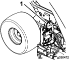
Inspecting and Cleaning the Machine
When sweeping has been completed, thoroughly clean the machine. Air dry the hopper. After cleaning, inspect the machine for possible damage to the mechanical components. Performing these procedures ensures that the machine performs satisfactorily during the next sweeping operation.
Hauling the Machine
-
Use care when loading or unloading the machine into a trailer or a truck.
-
Use full-width ramps for loading the machine into a trailer or a truck.
-
Never transport the machine when the transport alarm and the light are activated.
-
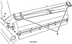
When transporting the machine, use the tie-downs to secure the front of the machine (Figure 30) and the axle (Figure 31) to secure the rear of the machine to the trailer.
Note: Transporting the machine without using the tie-downs could damage the machine.
Operating the Machine in Cold Weather
The hydraulic fluid in the machine must reach an operating temperature of 82°C (180°F) for proper operation of the floating machine head.
Switching the Sweeper-Up Mode
The Sweeper-Up button has 2 possible modes: standard and optional.
The standard mode allows you to raise the machine to the pre-defined heights. Refer to Sweeper Up Button—Standard Mode
The optional mode allows you to adjust the machine to any desired height and it stops at the pre-defined heights. Refer to Sweeper Up Button—Optional Mode.
-
Remove the cover off the control module.
-
Unplug the 2 wire connections from the pigtail connector shown in Figure 32.
-
Plug the 2 wire connections into the existing pigtail connector tethered to the wire harness.
-
Install the cover onto the control module.
Note: To return to standard mode, install the original pigtail connector.
After Operation Safety
-
Allow the machine to cool before storing the machine in any enclosure.
-
Keep all parts of the machine in good working condition and all hardware tightened.
-
Replace all worn, damaged, or missing decals.
Maintenance
Recommended Maintenance Schedule(s)
| Maintenance Service Interval | Maintenance Procedure |
|---|---|
| After the first 10 hours |
|
| Every 25 hours |
|
| Every 50 hours |
|
| Every 100 hours |
|
| Every 200 hours |
|
| Every 600 hours |
|
Maintenance Safety
-
Before servicing or making adjustments to the machine, stop the tow vehicle, shut off the engine, engage the parking brake, remove the key, and wait for all moving parts to stop.
-
Perform only those maintenance instructions described in this manual. If major repairs are ever needed or assistance is desired, contact an authorized Toro distributor.
-
Ensure that the machine is in safe operating condition by keeping nuts, bolts, and screws tight.
-
If possible, do not perform maintenance while the engine is running. Keep away from moving parts.
-
Carefully release pressure from components with stored energy.
-
Support the machine with blocks or storage stands when working beneath it. Never rely on the hydraulic system to support the machine.
-
Check the tine mounting bolts daily to be sure that they are tightened to specification.
-
Ensure that all guards are installed and secured shut after maintaining or adjusting the machine.
Hydraulic System Safety
-
Seek immediate medical attention if fluid is injected into skin. Injected fluid must be surgically removed within a few hours by a doctor.
-
Ensure that all hydraulic-fluid hoses and lines are in good condition and all hydraulic connections and fittings are tight before applying pressure to the hydraulic system.
-
Keep your body and hands away from pinhole leaks or nozzles that eject high-pressure hydraulic fluid.
-
Use cardboard or paper to find hydraulic leaks.
-
Safely relieve all pressure in the hydraulic system before performing any work on the hydraulic system.
Lubricating the Machine
| Maintenance Service Interval | Maintenance Procedure |
|---|---|
| Every 50 hours |
|
The machine has 11 grease fittings that require lubrication with No. 2 lithium grease.
-
Lubricate the following grease fittings:
-
Wipe the grease fittings clean to prevent foreign matter from entering into the bearing or bushing.
-
Pump grease into the bearing or bushing.
-
Wipe up any excess grease.
Associating the Remote Control and the Base Unit
Important: Read the entire procedure before performing the procedure.
The remote control must establish communications with the base unit before you can use the system. The remote control is associated to the system base unit before leaving the factory using the associate procedure. In situations where it is necessary to re-establish remote control-to-base unit communications (e.g., introducing a new or spare remote control to an existing base unit), do the following.
Note: Associating the remote control to a different base unit disassociates that remote control from the original base unit.
-
Remove power from the base unit.
-
Stand near the base unit in unobstructed, clear line-of-sight with the remote control in hand.
-
Simultaneously press and hold the OFFSET LEFT and OFFSET RIGHT buttons. The LED blinks about once per second.
-
Continue to hold both buttons until the LED begins blinking about twice per second.
-
Release the buttons.
-
Press and hold the OFFSET LEFT button. The LED blinks about twice per second.
-
Continue holding the OFFSET LEFT button and turn the key start to the RUN position. The LED turns solid if the procedure is successful.
Note: This could take up to 20 seconds.
-
Release the OFFSET LEFT button.
The system is ready for use with that particular remote control.
Replacing the Remote Batteries
The handheld remote is powered by 4 AAA batteries. When installing batteries, observe proper polarity as marked on the inside of the compartment to avoid damaging the unit.
-
Remove the 6 screws from the back of the remote and remove the cover (Figure 40).
Note: If possible, leave the rubber seal and steel gasket in the channel when removing the cover and batteries.
-
Remove the discharged batteries and properly dispose in accordance with local regulations.
-
Plug each fresh battery into a terminal cradle observing proper polarity.
Note: If the batteries are improperly installed, the unit will not be damaged, but it will fail to operate.
-
If you accidentally removed the rubber seal and the steel gasket, replace them carefully into the channel in the handheld remote.
-
Replace the cover and secure it with the 6 screws removed previously (Figure 40) and torque them to 1.5 to 1.7 N∙m (13 to 15 in-lb).
Note: Do not overtighten the screws.
Storage
-
Thoroughly clean the machine so that it is free of dirt, leaves, and debris.
-
Check the tire pressure. Refer to Checking the Tire Pressure.
-
Check all fasteners and tighten them as necessary.
-
Grease all the grease fittings. Wipe off any excess lubricant.
-
Check the condition of the brush and replace it if necessary.
Troubleshooting
| Condition | Possible Causes | Corrective Action |
| The machine is not picking up debris. |
The brush is damaged. The brush height is too high. The front flap height is too low or too high. |
Replace the brush. Adjust the brush height; refer to Adjusting the Brush Height. Adjust the front flap height; refer to Adjusting the Front Flap Height. |
| The machine has excessive vibration. |
Check the bearings on the brush shaft. If they are excessively hot, check the bearings for damage. Foreign materials are wrapped around brush. |
Replace any damaged bearings. Clean off any foreign objects. |
| The diagnostic light on the machine does not illuminate when pressing a remote button. |
There is frequency interference. |
Associate the remote control to the base unit; refer to Associating the Remote Control and the Base Unit . |
Checking Fault Codes
If the diagnostic light indicates that there is a system fault (refer to Diagnostic Light, check the fault codes to determine what is wrong with the machine.
Entering Diagnostic Mode and Checking the Codes
-
Turn the key to the RUN position.
-
Disconnect the power by separating the vehicle harness from the machine harness.
-
Remove the front cover.
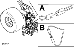
-
Pull the tethered cap off the 2 diagnostic shunt connectors (Figure 41A).
-
Connect the diagnostic shunt connectors together (Figure 41B).
-
Connect the vehicle and machine wire harness together to power the machine.
-
Count the number of flashes to determine the fault code, then consult the following table:
Note: If there are multiple faults, both faults flash, a long pause follows, then the flash sequences repeat.
Code LED Flash Pattern Behavior Details Machine Specific Faults 11 Blink once, pause, blink once, long pause, then repeat Lost communication with BASE Connector not plugged in; locate the loose or disconnected harness connector and connect it. Something wrong in the wiring; contact your authorized Toro distributor. BASE is bad; contact your authorized Toro distributor. 12 Blink once, pause, blink twice, long pause, then repeat Version incompatibility of the BASE and/or HH Wrong software (install the correct software from TORODIAG); contact your authorized Toro distributor. 13 Blink once, pause, blink 3 times, long pause, then repeat Wrong HH—not implemented on Rev A There is an incorrect product association (e.g., trying to update software on a MH-400 with a ProPass handheld) -
Install the front cover.
Resetting the Fault Codes
After solving the problem, disconnect and connect the diagnostic connectors. The diagnostic light flashes continuously once per second.