


Maintenance
Note: Determine the left and right sides of the machine from the normal operating position.
Recommended Maintenance Schedule(s)
| Maintenance Service Interval | Maintenance Procedure |
|---|---|
| After the first 10 operating hours |
|
| After the first 50 operating hours |
|
| After the first 200 operating hours |
|
| Before each use or daily |
|
| Every 50 hours |
|
| Every 100 hours |
|
| Every 150 hours |
|
| Every 200 hours |
|
| Every 250 hours |
|
| Every 400 hours |
|
| Every 800 hours |
|
| Every 1,500 hours |
|
| Every 2 years |
|
Important: Refer to your engine owner's manual for additional maintenance procedures. A Service Manual is also available for purchase from your uthorized Toro distributor.
Note: To obtain an electrical schematic or a hydraulic schematic for your machine, visit www.Toro.com.
Pre-Maintenance Procedures
Maintenance Safety
-
Before adjusting, cleaning, repairing, or leaving the machine, do the following:
-
Park the machine on a level surface.
-
Move the throttle switch to the low-idle position.
-
Disengage the cutting units.
-
Lower the cutting units.
-
Ensure that the traction is in neutral.
-
Engage the parking brake.
-
Shut off the engine and remove the key.
-
Wait for all moving parts to stop.
-
Allow machine components to cool before performing maintenance.
-
-
If the cutting units are in the transport position, use the positive mechanical lock (if available) before you leave the machine unattended.
-
If possible, do not perform maintenance while the engine is running. Keep away from moving parts.
-
Use jack stands to support the machine or components when required.
-
Carefully release pressure from components with stored energy.
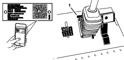
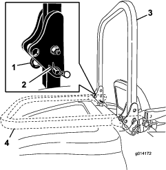
Using the Hood-Prop Rod
-
Release the hood latches.
-
Lift up the hood until you can position the prop rod behind the frame tube (Figure 27).
-
Lower the hood until the prop rod is in front of and resting against the frame tube.
-
To lower the hood, raise the hood until you can raise the prop rod above the frame tube, then lower the hood.
-
Secure the hood latches.
Lubrication
Greasing the Bearings and Bushings
The machine has grease fittings that you must lubricate regularly with No. 2 lithium grease. Lubricate the grease fittings immediately after every washing, regardless of interval specified.
-
Wipe the grease fittings clean so that foreign matter cannot be forced into the bearing or bushing (Figure 29).
-
Pump the grease into the fittings.
-
Wipe off any excess grease.
Note: To access the grease fittings for the rear-steering linkage, remove the storage compartment.
Note: Raise the machine off the floor with a jack and secure it with jack stands to allow better grease migration through both the upper and lower king-pin bushings. You should see grease purging out of both the top and the bottom of the axle casting/bushing assembly areas of all 4 kingpin assemblies (Figure 30).
Note: Do not wash the machine when it is still hot and avoid directing high-pressure or high-volume spray at the bearings or seals.
Engine Maintenance
Engine Safety
-
Shut off the engine before checking the oil or adding oil to the crankcase.
-
Do not change the governor speed or overspeed the engine.
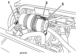
Servicing the Air Cleaner
Check the air-cleaner body for damage that could cause an air leak. Replace a damaged air cleaner. Check the whole intake system for leaks, damage, or loose hose clamps.
Service the air-cleaner filter only when the service indicator (Figure 30) requires it. Changing the air filter before it is necessary only increases the chance of dirt entering the engine when you remove the filter.
Important: Be sure that the cover is seated correctly and seals with the air-cleaner body.
-
Release the latch securing the air-cleaner cover to the air-cleaner body (Figure 30).
-
Remove the cover from the air-cleaner body. Before removing the filter, use clear and dry low-pressure air (276 kPa or 40 psi) to help remove large accumulations of debris packed between outside of the filter and the canister. Avoid using high-pressure air, which could force dirt through the filter into the intake tract.
Note: This cleaning process prevents debris from migrating into the intake when you remove the filter.
-
Remove and replace the filter.
Important: Do not clean the used element to prevent damaging the filter media. Inspect the new filter for shipping damage, checking the sealing end of the filter and the body. Do not use a damaged element. Insert the new filter by applying pressure to the outer rim of the element to seat it in the canister. Do not apply pressure to the flexible center of the filter.
-
Clean the dirt-ejection port located in the removable cover.
-
Remove the rubber outlet valve from the cover, clean the cavity and replace the outlet valve.
-
Install the cover orienting the rubber outlet valve in a downward position—approximately between the 5 o’clock to 7 o’clock positions when viewed from the end.
-
Secure the latch.
Checking the Engine-Oil Level
The engine is shipped with oil in the crankcase; however, check the oil level before and after you start the engine for the first time.
The crankcase capacity is approximately 5.2 L (5.5 US qt) with the filter.
Use high-quality engine oil that meets the following specifications:
-
API Classification Level Required: CH-4, CI-4 or higher
-
Preferred oil: SAE 15W-40 (above 0°F)
-
Alternate oil: SAE 10W-30 or 5W-30 (all temperatures)
Toro Premium Engine Oil is available from your distributor in either 15W-40 or 10W-30 viscosity.
-
Perform the pre-maintenance procedure; refer to Maintenance Safety.
-
Open the hood.
-
Remove the dipstick, wipe it clean, and install it (Figure 31).
-
Remove dipstick and check the oil level on dipstick. The oil level should be up to the FULL mark.
-
If the oil level is below the FULL mark, remove the fill cap (Figure 31) and add oil until level reaches the FULL mark on dipstick. Do not overfill.
Important: Be sure to keep the engine oil level between the upper and lower limits on the oil gauge. Engine failure may occur as a result of over filling or under filling the engine oil and running the engine.
-
Install the oil fill cap and close the hood.
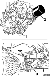
Changing the Engine Oil and Filter
-
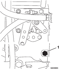
Remove the drain plug (Figure 32) and let the oil flow into a drain pan.
-
When the oil stops, install the drain plug.
-
Remove the oil filter (Figure 32).
-
Apply a light coat of clean oil to the new filter seal.
-
Install the replacement oil filter to the filter adapter. Turn the oil filter clockwise until the rubber gasket contacts the filter adapter, then tighten the filter an additional 1/2 turn.
Important: Do not overtighten the filter.
-
Add oil to the crankcase; refer to Checking the Engine-Oil Level.
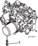
Adjusting the Throttle
-
Move the throttle lever forward to the front of the control panel slot and then move it back approximately 3 mm (1/8 inch) into the FAST idle position.
-
Check the position of the speed control lever on the fuel-injection pump. The speed-control lever should contact the high-speed screw when the throttle-control lever is in the FAST (detent) position (Figure 33).
-
If necessary, adjust the position of the jam nuts on the throttle-control cable until the speed-control lever contacts the high-speed screw when the throttle-control lever is in the FAST (detent) position (Figure 33).
-
Ensure that the cable jam nuts are fully tightened after the adjustment.
Fuel System Maintenance
Note: Refer to Adding Fuel for the proper fuel recommendations.
Danger
Under certain conditions, diesel fuel and fuel vapors are highly flammable and explosive. A fire or explosion from fuel can burn you and others and can cause property damage.
-
Use a funnel and fill the fuel tank outdoors, in an open area, when the engine is off and is cold. Wipe up any fuel that spills.
-
Do not fill the fuel tank completely full. Add fuel to the fuel tank until the level is to the bottom of the filler neck.
-
Never smoke when handling fuel and stay away from an open flame or where a spark my ignite fuel fumes.
-
Store fuel in a clean, safety-approved container and keep the cap in place.
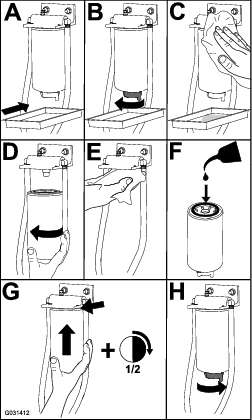
Servicing the Water Separator
Service the water separator as shown in Figure 34.
Bleeding the Fuel System
You must bleed the fuel system before starting the engine if any of the following have occurred:
-
Initial start up of a new machine
-
The engine has ceased running due to lack of fuel.
-
Maintenance has been performed upon fuel system components (i.e., filter replaced, separator serviced, etc.)
-
Perform the pre-maintenance procedure; refer to Checking the Tire Pressure and ensure that the fuel tank is at least half full.
-
Open the hood and secure it with the prop rod.
-
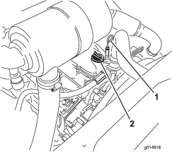
Open the air-bleed screw on the fuel-injection pump (Figure 35) with a 12 mm wrench.
-
Turn the key in the ignition switch to the ON position. The electric fuel pump will begin operation, thereby forcing air out around the air bleed screw. Leave the key in the ON position until a solid stream of fuel flows out around the screw.
-
Tighten the screw and turn the key to the OFF position.
Note: The engine should start after you perform this procedure. However, if engine does not start, air may be trapped between injection pump and the injectors; refer to Bleeding Air from the Fuel Injectors.
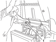
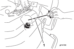
Bleeding Air from the Fuel Injectors
Note: Use this procedure only if the fuel system has been purged of air through normal priming procedures and the engine does not start; refer to Bleeding the Fuel System.
-
Loosen the pipe connection to the No. 1 nozzle and holder assembly (Figure 36).
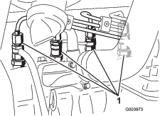
-
Turn the key in the key switch to the ON position and watch the fuel flow around the connector. When you observe a solid flow of fuel, turn the key to the OFF position.
-
Tighten the pipe connector securely.
-
Repeat steps 1 through 3 for the remaining nozzles.
Cleaning the Fuel Tank
Drain and clean the fuel tank every 2 years. Also, remove and clean the in-line strainers after draining the tank. Use clean diesel fuel to flush out the tank.
Important: Drain and clean the tank if the fuel system becomes contaminated or if you store the machine for an extended period of time.
Checking the Fuel Lines and Connections
Inspect the fuel lines for deterioration, damage, chaffing, or loose connections.
Electrical System Maintenance
Electrical System Safety
-
Disconnect the battery before repairing the machine. Disconnect the negative terminal first and the positive last. Connect the positive terminal first and the negative last.
-
Charge the battery in an open, well-ventilated area, away from sparks and flames. Unplug the charger before connecting or disconnecting the battery. Wear protective clothing and use insulated tools.
Servicing the Battery
Keep the top of the battery clean. If you store the machine in a location where temperatures are extremely high, the battery discharges more rapidly than if the machine is stored in a cool location.
Keep the top of the battery clean by washing it periodically with a brush dipped in ammonia or bicarbonate of soda solution. Flush the top surface with water after cleaning it. Do not remove the fill caps while cleaning the battery.
The battery cables must be tight on the terminals to provide good electrical contact.
If corrosion occurs at the terminals, disconnect the cables, negative (-) cable first, and scrape the clamps and terminals separately. Connect the cables, positive (+) cable first, and coat the terminals with petroleum jelly.
Warning
Battery terminals or metal tools could short against metal machine components, causing sparks. Sparks can cause the battery gasses to explode, resulting in personal injury.
-
When removing or installing the battery, do not allow the battery terminals to touch any metal parts of the machine.
-
Do not allow metal tools to short between the battery terminals and metal parts of the machine.
Warning
Incorrect battery cable routing could damage the machine and cables causing sparks. Sparks can cause the battery gasses to explode, resulting in personal injury.
-
Always disconnect the negative (black) battery cable before disconnecting the positive (red) cable.
-
Always connect the positive (red) battery cable before connecting the negative (black) cable.
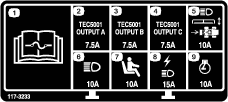
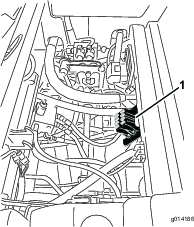
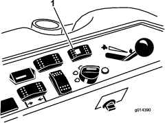
Checking the Fuses
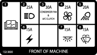
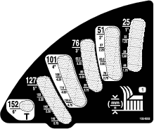
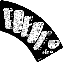
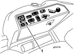
If the machine stops or has other electrical-system issues, check the fuses. Grasp each fuse in turn and remove them 1 at a time, checking to see if any are blown. If you need to replace a fuse, always use the same type and amperage rated fuse as the 1 you are replacing; otherwise, you could damage the electrical system (refer to the decal next to the fuses for a diagram of each fuse and its amperage).
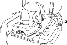
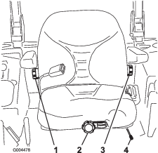
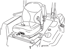
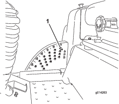
The traction-unit fuses are located under the seat (Figure 37).
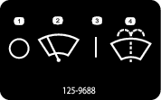
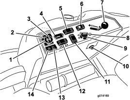
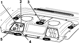
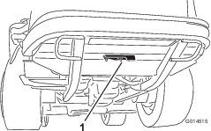
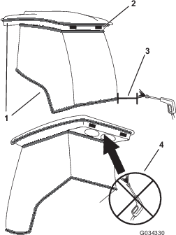
The cab fuses are located in the fuse box on the cab headliner (Figure 38).
Storing the Battery
If you store the machine for more than 30 days, remove the battery and charge it fully. Either store it on a shelf or on the machine. Leave the cables disconnected if you store it on the machine. Store the battery in a cool atmosphere to avoid quick deterioration of the charge in the battery. To prevent the battery from freezing, ensure that it is fully charged. The specific gravity of a fully charged battery is 1.265 to 1.299.
Drive System Maintenance
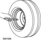
Checking the Tire Pressure
Maintain the air pressure in the front and rear tires. The correct air pressure is 172 kPa (25 psi) in the rear tires and 103 kPa (15 psi) in the front tires. If a cab is installed on the machine, the front and rear tires should be inflated to 172 kPa (25 psi). Uneven tire pressure can cause an uneven cut. Check the tires when they are cold to get the most accurate pressure reading.
Correcting the Steering Misalignment
-
Press the steering-selector switch rearward 4-wheels steering position (Figure 40).
-
On a paved or dirt surface, turn the steering wheel to the left or right and continue turning until all 4 wheels have stopped turning. Automatic synchronization of the wheel alignment should occur.
Important: Doing this procedure on turf can result in turf damage directly under each of the turning tires.
Cooling System Maintenance
Cooling System Safety
-
Swallowing engine coolant can cause poisoning; keep out of reach from children and pets.
-
Discharge of hot, pressurized coolant or touching a hot radiator and surrounding parts can cause severe burns.
-
Always allow the engine to cool at least 15 minutes before removing the radiator cap.
-
Use a rag when opening the radiator cap, and open the cap slowly to allow steam to escape.
-
-
Do not operate the machine without the covers in place.
-
Keep your fingers, hands and clothing clear of rotating fan and drive belt.
-
Shut off the engine and remove the key before performing maintenance.
Checking the Cooling System
The cooling system is filled with a 50/50 solution of water and permanent ethylene glycol anti freeze. Check the level of the coolant in the expansion tank at the beginning of each day before starting the engine. The capacity of the cooling system is 7.5 L (6 US qt).
-
Check the level of the coolant in the expansion tank (Figure 41). The coolant level should be between the marks on the side of the tank.
-
If coolant level is low, remove the expansion tank cap and replenish the system. Do not overfill.
-
Install the expansion-tank cap.
Cleaning the Radiator
Keep the radiator clean to prevent the engine from overheating.
Note: If the attachment or engine shuts off due to overheating, first check the radiator for an excessive buildup of debris.
-
Open the hood and secure the prop rod.
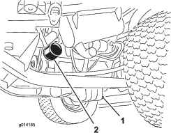
-
Loosen the flange nut securing the clean-out cover to the underside of the rear frame (Figure 42). Rotate the cover to the side to expose the clean-out hole in the frame.
-
Working from the fan side of the radiator, blow out debris with low-pressure (50 psi) compressed air (do not use water). Repeat this step from the front of the radiator, again from the fan side.
-
After you have thoroughly cleaned the radiator, remove any debris from the channel at the radiator base and around the frame.
-
Clean the engine compartment and the brake linkage.
-
Close the clean-out cover and secure the flange nut.
-
Close the hood.
Brake Maintenance
Adjusting the Brakes
Adjust the service brakes when there is more than 25 mm (1 inch) of free travel of the brake pedal, or when the brakes do not work effectively. Free travel is the distance that the brake pedal moves before you feel braking resistance.
Note: Use the wheel-motor backlash to rock the drums back and forth to ensure that the drums are free prior to and after adjustment.
-
To reduce free travel of the brake pedals, tighten the brakes by loosening the front nut on the threaded end of the brake cable (Figure 43).
-
Tighten the rear nut to move the cable backward until brake pedals have 1.27 to 1.9 cm (1/2 to 3/4 inch) of free travel before the wheels lock up.
-
Tighten the front nuts, ensuring that both cables actuate the brakes simultaneously.
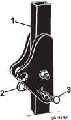
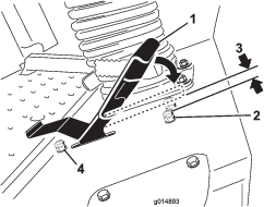
Adjusting the Parking Brake
If the parking brake fails to engage, adjust the brake pawl.
-
Loosen the 2 screws securing the parking-brake pawl to the frame (Figure 44).
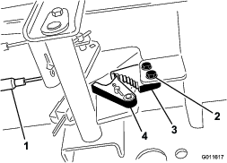
-
Press the parking brake pedal forward until the brake detent completely engages on the brake pawl (Figure 44).
-
Tighten the 2 screws locking the adjustment.
-
Press the brake pedal to release the parking brake.
-
Check the adjustment and adjust it as required.
Belt Maintenance
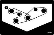
Checking the Alternator Belt
-
Open the hood and secure the prop rod.
-
Check the tension of the alternator belt by pressing it (Figure 45) midway between the alternator and the crankshaft pulleys with 10 kg (22 lb) of force.
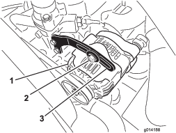
The belt should deflect 11 mm (7/16 inch). If the deflection is incorrect, proceed to step 3. If it is correct, you are finished with this procedure.
-
Loosen the bolt securing the brace to the alternator (Figure 45) and the alternator pivot bolt.
-
Insert a pry bar between the alternator and the engine and pry on the alternator.
-
When you achieve the proper tension, tighten the alternator, brace, and pivot bolts to secure the adjustment.
Controls System Maintenance
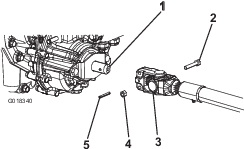
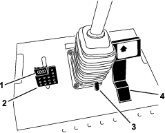
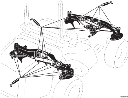
Adjusting the Traction Drive for Neutral
Note: If the machine has recently had the hydraulic fluid changed or the traction motors or hoses replaced, work out any air trapped in the system prior to performing this procedure. To do this, operate the machine in forward and reverse for a few minutes and then replenish the oil as required.
Note: When positioned on a level surface, the machine must not creep when you release the traction pedal.
-
Park the machine on a level surface, engage the parking brake, lower the cutting unit to the floor, and shut off the engine.
-
Jack up the rear of the machine until the rear tires are off the shop floor. Support the machine with jack stands to prevent it from falling.
Note: On 4-wheel-drive models, the front tires must also be off the shop floor and supported by jack stands.
Warning
The engine must be running so that you can perform this adjustment. This could cause personal injury.
Keep your hands, feet, face, and other body parts away from any hot parts of the engine and any rotating parts.
-
Start the engine, set the throttle to the SLOW position, and observe which direction the rear tires rotate.
Important: Make sure that the traction pedal is in the NEUTRAL position.
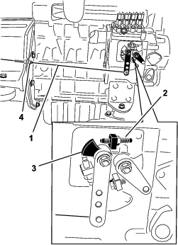
-
If the left rear tire is rotating, loosen the jam nuts on the left side transmission control rod (Figure 46).
Note: The forward end of the control rod has a left-hand thread. The rear end of the rod, which is connected to the transmission, has a right-hand thread.
-
If the left rear tire is rotating in reverse, lengthen the rod by slowly turning the rod counterclockwise (as viewed from the front) until the left rear tire stops rotating or has minimal rotation in reverse.
-
If the left rear tire is rotating forward, shorten the rod by slowly turning the rod clockwise (as viewed from the front) until the left rear tire stops rotating.
-
-
Move the throttle to the FAST position. Make sure that the wheel remains stopped or has minimal rotation in reverse. Adjust it as required.
-
Tighten the jam nuts.
-
Repeat the procedure for the right rear tire, if required, by using the right-side transmission control rod.
-
Shut off the engine, remove the jack stands, and lower the machine to the shop floor.
-
Test drive the machine to make sure that it does not creep.
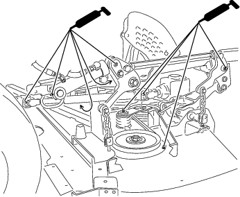
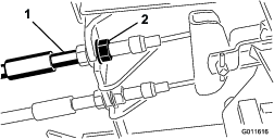
Adjusting the Maximum Ground Speed
-
Park the machine on a level surface, disengage the PTO, release the traction pedal to the NEUTRAL position, and engage the parking brake.
-
Move the throttle lever to the SLOW position, shut off the engine, remove the key, and wait for all moving parts to stop before leaving the operating position.
-
Loosen the jam nut on the stop bolt for the traction pedal (Figure 47).
-
Adjust the stop bolt all the way in (away from the traction pedal).
-
Using your hand, push the traction pedal all the way forward, with light pressure, until it stops and hold it there.
Note: Maintain only light pressure on the pedal when pushing it to the full forward position.
-
With the seat in the raised position, verify that you are not over loading the linkage by making sure the transmission does not move when you press the pedal to the stop.
-
Adjust the stop bolt out (toward the traction pedal) until there is a gap of 1.5 mm (0.060 inch) between the head of the stop bolt and the bottom of the traction pedal.
-
Tighten the jam nut to secure the stop bolt in place.
-
To change the reverse speed, you can adjust the reverse stop bolt. To increase the reverse speed, adjust the stop bolt in; to decrease the reverse speed, adjust the stop bolt out.
Hydraulic System Maintenance
The reservoir is filled at the factory with approximately 17 L (18US qt) of high-quality tractor transmission/hydraulic fluid. The recommended replacement fluid is as follows:
| Toro Premium Transmission/Hydraulic Tractor Fluid (Available in 5 gallon pails or 55 gallon drums. See parts catalog or Toro Distributor for part numbers.) |
Alternate fluids: If the Toro fluid is not available, you can use Mobil® 424 hydraulic fluid.
Note: Toro will not assume responsibility for damage caused by improper substitutions.
Note: Many hydraulic fluids are almost colorless, making it difficult to spot leaks. A red dye additive for the hydraulic system oil is available in 20 ml (2/3 oz) bottles. A bottle is sufficient for 15 to 22 L (4 to 6 US gallons) of hydraulic fluid. Order Part No. 44-2500 from your authorized Toro Distributor.
Hydraulic System Safety
-
Seek immediate medical attention if fluid is injected into skin. Injected fluid must be surgically removed within a few hours by a doctor.
-
Ensure that all hydraulic-fluid hoses and lines are in good condition and all hydraulic connections and fittings are tight before applying pressure to the hydraulic system.
-
Keep your body and hands away from pinhole leaks or nozzles that eject high-pressure hydraulic fluid.
-
Use cardboard or paper to find hydraulic leaks.
-
Safely relieve all pressure in the hydraulic system before performing any work on the hydraulic system.
Checking the Hydraulic System
The reservoir is filled at the factory with approximately 17L (18US qt) of high-quality tractor transmission/hydraulic fluid. The recommended replacement fluid is as follows:
Toro Premium Transmission/Hydraulic Tractor Fluid (Available in 19 L (5 gallon) pails or 208 L (55 gallon) drums. See the Parts Catalog or your authorized Toro distributor for part numbers).
Alternate fluids: If the Toro fluid is not available, you may use Mobil® 424 hydraulic fluid.
Note: Toro will not assume responsibility for damage caused by improper substitutions.
Note: Many hydraulic fluids are almost colorless, making it difficult to spot leaks. A red dye additive for the hydraulic system oil is available in 20ml (2/3fl oz) bottles. One bottle is sufficient for 15 to 22 L (4 to 6 US gallons) of hydraulic fluid. Order Part No. 44-2500 from your authorized Toro distributor.
-
Park the machine on a level surface, release the traction pedal to the NEUTRAL position, and start the engine.
-
Run the engine at the lowest possible speed to purge the system of air.
Important: Do not engage the PTO.
-
Raise the deck to extend the lift cylinders, shut off the engine, and remove the key.
-
Remove the hydraulic-filler cap (Figure 48) from the filler neck.
-
Remove the dipstick and wipe it with a clean rag (Figure 48).
-
Screw the dipstick all the way into the filler neck; then remove it, and check the level of the fluid (Figure 48).
If the level is not within the notched area of the dipstick, add enough high-quality hydraulic fluid to raise the level to within the notched area. Do not overfill the hydraulic system.
-
Replace the dipstick and thread the fill cap finger-tight onto the filler neck.
-
Check all hoses and fittings for leaks.
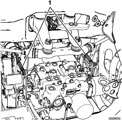
Changing the Hydraulic Fluid And Filter
-
Disengage the PTO, release the traction pedal to the NEUTRAL position, and engage the parking brake.
-
Move the throttle lever to the SLOW position, shut off the engine, remove the key, and wait for all moving parts to stop before leaving the operating position.
-
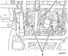
Place a large pan under the hydraulic reservoir and transmission case and remove the plugs, draining all of the hydraulic fluid (Figure 49).
-
Clean the area around the hydraulic-fluid filter and remove the filter (Figure 49).
-
Immediately install a new hydraulic-fluid filter.
-
Install the drain plugs in the hydraulic reservoir and the transmission case.
-
Fill the reservoir to the proper level; refer to Checking the Hydraulic System.
-
Start the engine and check for fluid leaks. Allow the engine to run for about 5 minutes, then shut it off.
-
After 2 minutes, check the level of the hydraulic fluid; refer to Checking the Hydraulic System.
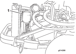
Filling the Washer-Fluid Bottle
-
Perform the pre-maintenance procedure; refer to Maintenance Safety.
-
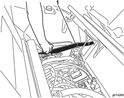
Open the hood and locate the washer-fluid bottle (Figure 50).
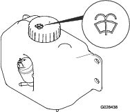
-
Fill the bottle with washer fluid as needed.
-
Close the hood.
Cleaning the Cab Air Filters
-
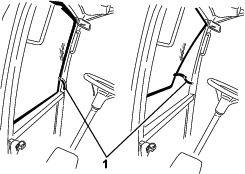
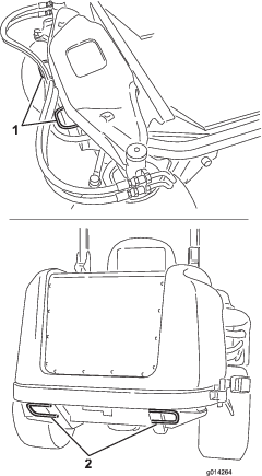
Remove the screws and grates from both the in-cab and rear cab air filters (Figure 51 and Figure 52).
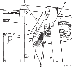
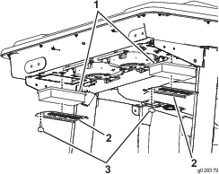
-
Clean the filters by blowing clean, oil-free, compressed air through them.
Important: If either filter has a hole, tear, or other damage, replace the filter.
-
Install the filters and the grate with the thumbscrews.
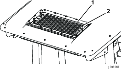
Cleaning the Air-Conditioning Coil
-
Perform the pre-maintenance procedure; refer to Maintenance Safety.
-
Lift the 4 tabs on the air-conditioning screen (Figure 53) and remove the screen from the top of the cab.
-
Disconnect the plug and cord for the fans from the outlet (Figure 54).
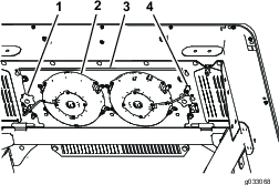
-
Remove the 2 knobs that secure the fan-panel assembly and fans to the underside of the cab top (Figure 54) and remove the assembly.
-
Clean the screen, air-conditioning duct, fans, and fan panel using low-pressure air no greater than 276 kPa (40 psi).
Important: Do not use water to clean the condenser because moisture on the components attracts dirt and dust, which make the components more difficult to clean.
-
Install the fan-panel assembly and fans to the underside of the cab top with the 2 knobs that you loosened and removed in step 4.
-
Connect the cord for the fans that you disconnected in step 3 into the outlet.
-
Install the air-conditioning screen in the opening in the top of the cab and secure it by closing the 4 tabs on the screen.
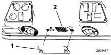
Cleaning
Cleaning the Cab
Important: Use care around the cab seals and lights (Figure 55). If you are using a pressure washer, keep the washer wand at least 0.6 m (2 ft) away from the machine. Do not use the pressure washer directly on the cab seals and lights or under the rear overhang.
Waste Disposal
Engine oil, batteries, hydraulic fluid, and engine coolant are pollutants. Dispose of these according to your state and local regulations.