Installation
Determine the left and right sides of the machine from the normal operating position.
Preparing the Machine
-
Park the machine on a level surface.
-
Disengage the power takeoff and lower the attachments.
-
Engage the parking brake.
-
Shut off the engine and remove the key.
-
Wait for all movement to stop.
-
Allow machine components to cool.
Installing the Deck Mount
Parts needed for this procedure:
| Deck mount | 1 |
| Plate | 1 |
| Spring pin | 1 |
| Spacer | 2 |
| Bolt (3/4 x 4-1/2 inches) | 1 |
| Locknut (3/4 inch) | 1 |
| Cable tie | 1 |
-
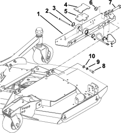
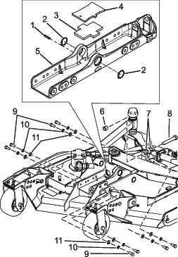
Remove the snap rings on both sides of the U-joint as shown in Figure 3.
-
Remove the caps under the snap rings. This can be done by adding more grease into the U-joint.
-
Remove the existing long bolt (Figure 3).
-
Remove the plate and rubber cushion (Figure 3). Discard the plate.
-
Remove the bolts that hold the deck mount to the cutting unit (Figure 3).
-
Remove the bolt, locknut, and spacers that secure the hydraulic cylinder to the deck mount. Discard the hardware and existing deck mount(Figure 3).
-
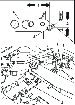
Using the new deck mount as a template, locate and drill a 9/16 inch hole into the rear plates on the cutting unit as shown in Figure 2.
-
Place the new deck mount onto the cutting unit.
-
Install the bolts that secure the deck mount to the cutting unit (Figure 3 and Figure 4); torque to 102 N∙m (75 ft-lb).
-
Install the U-joint caps and secure them with the previously removed snap rings (Figure 3).
-
Install the hydraulic cylinder to the deck mount with a bolt (3/4 x 4-1/2 inches), locknut (3/4 inch), and spacers (Figure 3); torque to 136 N∙m (100 ft-lb).
-
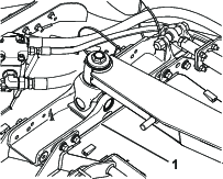
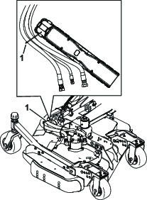
Install the cable tie (Figure 5).
-
Start the machine and check the operation of the cutting unit. Ensure no hoses rub against the machine and if needed, adjust the hoses.