Introduction

This blower is intended to be used by professional, hired operators. It is primarily designed to use wind power to quickly clear large areas of unwanted debris on well-maintained lawns, parks, golf courses, sports fields, and on commercial grounds.

Read this information carefully to learn how to operate and maintain your product properly and to avoid injury and product damage. You are responsible for operating the product properly and safely.

You may contact Toro directly at www.Toro.com for product safety and operation training materials, accessory information, help finding a dealer, or to register your product.

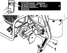
Whenever you need service, genuine Toro parts, or additional information, contact an Authorized Service Dealer or Toro Customer Service and have the model and serial numbers of your product ready. Figure 1 identifies the location of the model and serial numbers on the product. Write the numbers in the space provided.

Important: With your mobile device, you can scan the QR code on the serial number decal (if equipped) to access warranty, parts, and other product information.

g246145

This manual identifies potential hazards and has safety messages identified by the safety-alert symbol (Figure 2), which signals a hazard that may cause serious injury or death if you do not follow the recommended precautions.

g000502

This manual uses 2 words to highlight information. Important calls attention to special mechanical information and Note emphasizes general information worthy of special attention.

Warning

CALIFORNIA

Proposition 65 Warning

Use of this product may cause exposure to chemicals known to the State of California to cause cancer, birth defects, or other reproductive harm.

Safety

General Safety

This product is capable of throwing objects. Always follow all safety instructions to avoid serious personal injury.

Using this product for purposes other than its intended use could prove dangerous to you and bystanders.

  • Read and understand the contents of this Operator’s Manual before starting the engine.

  • Use your full attention while operating the machine. Do not engage in any activity that causes distractions; otherwise, injury or property damage may occur.

  • Do not put your hands or feet near moving components of the machine.

  • Do not operate the machine without all guards and other safety protective devices in place and working on the machine.

  • Keep clear of any discharge opening. Keep bystanders and pets a safe distance away from the machine.

  • Keep children out of the operating area. Never allow children to operate the machine.

  • Stop the machine, shut off the engine, and remove the key before servicing, fueling, or unclogging the machine.

Improperly using or maintaining this machine can result in injury. To reduce the potential for injury, comply with these safety instructions and always pay attention to the safety-alert symbol, which means Caution, Warning, or Danger—personal safety instruction. Failure to comply with these instructions may result in personal injury or death.

You can find additional safety information where needed throughout this Operator’s Manual.

Safety and Instructional Decals

Graphic

Safety decals and instructions are easily visible to the operator and are located near any area of potential danger. Replace any decal that is damaged or missing.

decal119-0217
decal137-3999

Setup

Important: Install the Low Flow Hydraulics Kit on your machine before installing this kit.

Preparing the Machine

  1. Park the machine on a level surface.

  2. Lower the A-frame.

  3. Disengage the PTO, engage the parking brake, and move the motion-control levers outward to the NEUTRAL-LOCK position.

  4. Shut off the engine and remove the key.

Installing the Wheel Weight Kit (Optional)

Parts needed for this procedure:

Wheel Weight Kit (sold separately)1

Installing wheel weights can improve traction on the machine when using the blower; refer to the Installation Instructions for the Wheel Weight Kit.

Positioning the Caster Wheels

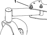
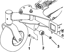
For both casters, remove the nut and bolt, move the caster to the front position, and install the nut and bolt (Figure 3). Torque to 91 to 113 N∙m (67 to 83 ft-lb).

g230693

Removing the Right Fan Guard

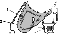
  1. Remove the fuel tank; refer to the Operator’s Manual for the machine.

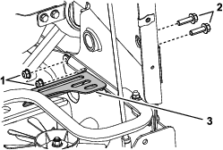
  2. Remove and retain the 2 bolts, 2 nuts, and the right fan guard (Figure 4).

    g246823
  3. Install the bolts and nuts you removed and torque to 41 to 49 N∙m (30 to 36 ft-lb).

  4. Install the fuel tank.

Installing the Blower

Parts needed for this procedure:

Blower assembly1
Bushing assembly2
Carriage bolt (3/8 x 2-1/4 inches)2
Locknut (3/8 inch) 2
Receiver hitch1
Heat shield1
Bumper 2
Thread-forming screw (1/4 x 1/2 inch)2
Stop bracket2
Carriage bolt (3/8 x 1 inch)2
Nut (3/8 inch)2
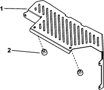
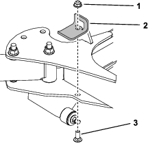
  1. Install the 2 bumpers on the heat shield (Figure 5).

    g246214
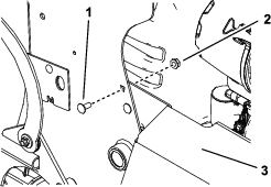
  2. Remove the top carriage bolt and nut securing the muffler guard to the machine (Figure 6).

    g246215
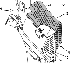
  3. Install the heat shield over the muffler guard, with the tabs inside the muffler guard, and secure it with 2 thread-forming bolts and the carriage bolt and nut you removed previously (Figure 7).

    Important: To minimize debris buildup on the muffler, the heat shield must be installed on the machine when using the blower.

    g250300
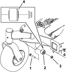
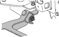
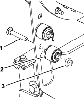
  4. Use a carriage bolt (3/8 x 2-1/4 inches) and nut (3/8 inch) to install the bushing assemblies to the machine (Figure 8). Torque the bolt to 37 to 45 N∙m (27 to 33 ft-lb).

    Note: The rubber flange of the bushing should face toward the inside of the machine as shown in Figure 8.

    g250302
  5. Use a carriage bolt (3/8 x 1 inch) and a locknut (3/8 inch) to install the stop brackets to both sides of the machine (Figure 9). Torque the bolt to 37 to 45 N∙m (27 to 33 ft-lb).

    g250341
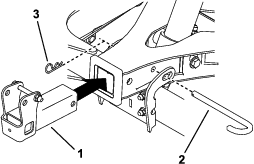
  6. Remove the hitch pin and cotter pin from the A-frame and use it to install the hitch receiver (Figure 10). Ensure that the pin locks the A-frame to the cross tube.

    g230752
  7. Move the blower in front of the machine and lay the belt underneath the machine so that it is lined up with the clutch (Figure 11).

    g230767
  8. Place the blower assembly forks onto the bushing assemblies (Figure 12).

    g250511
  9. Install the belt onto the clutch. Verify that the belt is still routed on the blower pulleys and is seated properly in the pulley grooves.

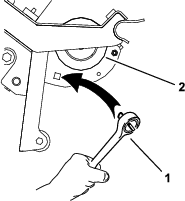
    Note: If needed, you may use a drive ratchet (1/2 inch) to move the left idler pulley (Figure 13).

    g231579
  10. Raise the blower as described in Raising the Blower.

  11. Connect the hydraulic hoses to the quick-disconnect couplings on the Low Flow Hydraulics Kit.

    Warning

    Hydraulic fluid escaping under pressure can penetrate skin and cause injury. Fluid injected into the skin must be surgically removed within a few hours by a doctor familiar with this form of injury; otherwise, gangrene may result.

    • Ensure that all hydraulic-fluid hoses and lines are in good condition and all hydraulic connections and fittings are tight before applying pressure to the hydraulic system.

    • Keep your body and hands away from pinhole leaks or nozzles that eject high-pressure hydraulic fluid.

    • Use cardboard or paper to find hydraulic leaks; never use your hands.

Operation

Operation Safety

  • The machine exceeds noise levels of 85 dB(A) at the operator’s position. Use hearing protection for prolonged exposure to reduce the potential of permanent hearing damage.

  • Wear appropriate clothing including eye protection; long pants; substantial, slip-resistant footwear; and hearing protection. Tie back long hair and do not wear loose clothing or loose jewelry.

  • Stay away from the nozzle opening when the machine is operating. Keep all bystanders away from the nozzle opening and don’t direct discharge toward bystanders.

  • When a person or pet appears unexpectedly in or near the operating area, stop operation. Careless operation, combined with terrain angles, ricochets, or improperly positioned guards can lead to thrown object injuries. Do not resume operation until the area is cleared of people and pets.

Operating the Blower

Important: Do not operate the blower without the heat shield installed on the machine.

To operate the blower, start the engine, move the motion-control levers to the center, unlocked position, move the throttle lever between half and full throttle, and engage the PTO (Figure 14).

g009174

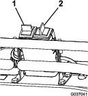
Use the right switch for the low flow kit to rotate the nozzle to the desired direction (Figure 15), and use the throttle lever to adjust the blower speed.

Note: If you would like to change the direction the nozzle rotates when you move the switch a particular direction, remove the quick-disconnect couplings from the Low-Flow Hydraulics Kit hoses and install them on the opposite hoses.

g037041

Ensure to clean debris from the machine regularly.

Warning

Discharged air has considerable force and could cause injury or loss of footing.

  • Stay away from the nozzle opening when the machine is operating.

  • Keep bystanders away from the nozzle opening when the machine is operating.

Using the Kickstand

Lowering the Blower

  1. Rotate the blower nozzle so that it points upward.

  2. Park the machine on a level surface, disengage the PTO, move the motion-control levers to the NEUTRAL-LOCK position, and engage the parking brake.

  3. Shut off the engine, remove the key, and wait for all moving parts to stop before leaving the operating position.

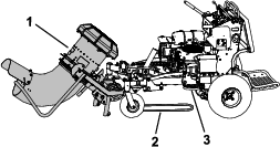
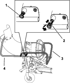
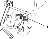
  4. Pull out the kickstand locking pins on both sides of the machine, rotate them 90 degrees so that they are disengaged, and rotate the kickstand away from the machine (Figure 16). Engage the pins and ensure that they snap into position.

    g230843
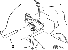
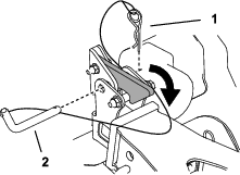
  5. Remove the hitch pin and hairpin cotter securing the blower assembly to the hitch receiver (Figure 17).

    g230859
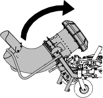
  6. Hold the kickstand and push the release lever down. Slowly lower the kickstand to the ground.

    Note: Once the lever disengages the hitch pin, the blower rotates down.

    g230858

Raising the Blower

  1. Raise the blower so that it latches on the hitch receiver (Figure 19 and Figure 20).

    g230769
    g230770
  2. Secure the assembly to the hitch receiver using the hitch pin and hairpin cotter attached to the receiver (Figure 20).

  3. Pull out the kickstand locking pins on both sides of the machine, rotate them 90 degrees so that they are disengaged, and raise the kickstand (Figure 21). Engage the knobs and ensure that the pins snap into position.

    g230843

Removing the Blower

  1. Park the machine on a level surface, disengage the PTO, engage the parking brake, and move the motion-control levers outward to the NEUTRAL-LOCK position.

  2. Shut off the engine and remove the key.

  3. Disconnect the blower hydraulic hoses from the quick-disconnect couplings on the Low Flow Kit.

  4. Lower the blower; refer to Lowering the Blower.

  5. Remove the belt from the clutch.

    Note: If needed, use a drive ratchet (1/2 inch) to move the left idler pulley (Figure 22).

    g231579
  6. Lift the blower assembly off the bushing assemblies on the machine.

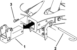
  7. Remove the hitch pin, cotter pin, and hitch receiver from the A-frame. Install the hitch pin and cotter pin to secure the A-frame (Figure 23).

    g246845
  8. Remove the stop brackets (Figure 24).

    g250341
  9. Remove both bushing assemblies (Figure 25).

    g230751
  10. Use the fasteners to store the bushing assemblies on the left side of the blower frame (Figure 26).

    g246867
  11. Remove the heat shield (Figure 27).

    Important: Whenever you install the blower on another machine, you must also install the heat shield.

    g246216
  12. Install the carriage bolt and nut to secure the muffler guard. Torque the bolt to 1978 to 2542 N∙cm (175 to 225 in-lb).

  13. Remove the fuel tank; refer to the Operator’s Manual for the machine.

  14. Remove the 2 bolts and 2 nuts from the right side of the machine and use them to install fan guard (Figure 28). Torque the bolts to 37 to 45 N∙m (27 to 33 ft-lb).

    g246823
  15. Install the fuel tank.

Operating Tips

  • Practice operating the blower. Blow the same direction the wind is blowing to prevent material from blowing back into the cleared area.

  • Be aware of the blower nozzle direction and do not point it at anyone.

  • Adjust the nozzle opening so that it blows under the debris.

  • Use caution when blowing around newly planted sod as the force of the air could disrupt the grass.

  • The nozzle outlet position affects the distance debris can be blown.

  • When you rotate the nozzle, rotate it upward and around to prevent blowing debris back into the cleared area.

Maintenance

Maintenance Safety

  • Park the machine on a level surface. Never allow untrained personnel to service the machine.

  • Use jack stands to support the machine when required.

  • Remove the key from the switch on the traction unit to prevent accidental starting of the engine when servicing, adjusting, or storing the machine.

  • Perform only those maintenance instructions described in this manual. If the blower requires a major repair, contact an authorized Toro distributor.

  • Ensure that the machine is in safe operating condition by keeping nuts, bolts, and screws tight.

  • Keep your hands and feet away from moving parts. Do not make adjustments with the engine running.

  • Keep all parts in good working condition and all hardware tightened. Replace all worn or damaged decals.

  • To ensure optimum performance and continued safety certification of the machine, use only genuine Toro replacement parts and accessories. Replacement parts and accessories made by other manufacturers could be dangerous, and such use could void the product warranty.

Checking the Belts

Maintenance Service IntervalMaintenance Procedure
Every 300 hours
  • Check the belts.
  • Check the belts for cracks, frayed edges, burn marks, or any other damage. Replace damaged belts.

    Replacing the Blower Belt

    1. Park the machine on a level surface, disengage the PTO, and engage the parking brake.

    2. Shut off the engine, remove the key, and wait for all moving parts to stop before leaving the operating position.

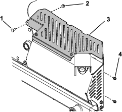
    3. Remove the belt cover (Figure 29).

      g246599
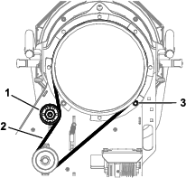
    4. Loosen the nut on the top pulley and slide the pulley up to release tension on the belt (Figure 30).
      g250730
    5. Remove the roller bearing (Figure 30).

    6. Remove the belt and install a new belt (Figure 30).

    7. Install the roller bearing (Figure 30)

    8. Slide the top pulley down until the belt deflection is 5 mm (0.19 inch) at the center of the largest span and tighten the nut (Figure 30).

    Replacing the Clutch Belt

    1. Park the machine on a level surface, disengage the PTO, and engage the parking brake.

    2. Shut off the engine, remove the key, and wait for all moving parts to stop before leaving the operating position.

    3. Lower the blower.

    4. Loosen the nozzle clamp and remove the nozzle.

    5. Remove the belt from the machine clutch.

      Note: If needed, use a drive ratchet (1/2 inch) to move the left idler pulley (Figure 13).

    6. Remove the belt from the fan pulley (Figure 31).
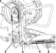
      g246640
    7. Route the belt down through the drive adapter assembly, around the idler pulleys, and around the clutch pulley (Figure 31). Ensure that the belt is seated properly in the pulley grooves.

      Note: If needed, you may use a drive ratchet (1/2 inch) to move the left idler pulley (Figure 13).

    Checking the Hydraulic Hoses

    Maintenance Service IntervalMaintenance Procedure
    Every 100 hours
  • Check the hydraulic hoses for leaks, loose fittings, kinked lines, loose mounting supports, wear, weather, and chemical deterioration.
  • Check the hydraulic hoses for leaks, loose fittings, kinked lines, loose mounting supports, wear, weather, and chemical deterioration.

    Warning

    Hydraulic fluid escaping under pressure can penetrate skin and cause injury. Fluid injected into the skin must be surgically removed within a few hours by a doctor familiar with this form of injury; otherwise, gangrene may result.

    • Ensure that all hydraulic-fluid hoses and lines are in good condition and all hydraulic connections and fittings are tight before applying pressure to the hydraulic system.

    • Keep your body and hands away from pinhole leaks or nozzles that eject high-pressure hydraulic fluid.

    • Use cardboard or paper to find hydraulic leaks; never use your hands.

    Removing Debris from the Machine

    Maintenance Service IntervalMaintenance Procedure
    After each use
  • Remove debris from the machine.
    1. Park the machine on a level surface, disengage the PTO, and engage the parking brake.

    2. Shut off the engine, remove the key, and wait for all moving parts to stop before leaving the operating position.

    3. Clean debris from the drives, muffler, and engine after each use.