Setup
Note: Determine the left and right sides of the machine from the normal operating position.
Installing the MyRide® Suspension
Parts needed for this procedure:
| Pin | 1 |
| Round clip | 2 |
-
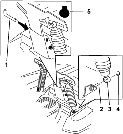
Raise the platform and remove the wooden block from above the battery.
Note: You can discard the wooden block.
-
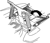
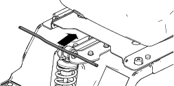
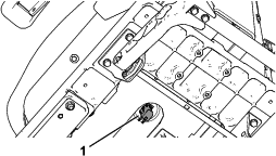
Rotate the suspension up (Figure 1).
-
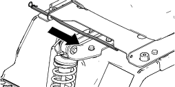
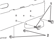
Place the ends of the springs on the posts (Figure 2).
-
Secure the springs to the posts with the 2 round clips (Figure 2).
-
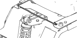
Install the pin into the back by using the indexed key slot (Figure 2).
Connecting the Battery
-
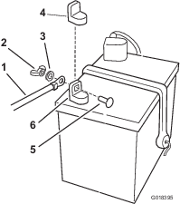
Locate the battery and negative battery cable.
-
Remove the plastic cap from the negative battery post.
-
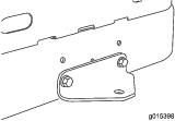
Remove the fasteners on the negative battery cable, and use them to secure the negative battery cable to the negative battery post (Figure 3).
Installing the Seat
-
Remove the 2 hairpin cotters from the seat-pivot rod, and remove the seat-pivot rod from the platform (Figure 4).
-
Place the seat assembly onto the platform (Figure 5).
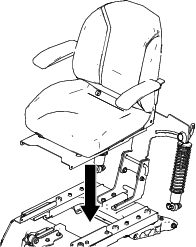
-
Install the seat-pivot rod by inserting the rod from the center and outward through the pivot bracket hole and seat pan hole (Figure 6).
Note: Ensure that the seat pan is between the 2 pivot brackets.
-
Install a hairpin cotter on 1 side of the seat-pivot rod, then slide the seat-pivot rod through the pivot bracket hole and seat pan hole (Figure 7).
-
Install the other hairpin cotter on the other side of the seat-pivot rod (Figure 8).
-
Rotate the seat assembly upward and connect the wire harness to the seat switch on the bottom of the seat (Figure 9).
Installing the Rear Hitch
Setting Up the Motion-Control Levers
-
Locate the motion-control levers attached, but folded down on the machine.
-
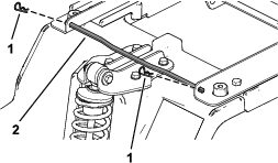
Remove the upper bolt (3/8 x 1 inch) and washer; loosen the lower bolt (3/8 x 1 inch).
-
Raise the motion control levers to the upright position.
-
Align the holes in the motion-control lever with the holes in the control-arm shaft, and install the bolt and washer removed previously. Repeat this for both control levers.
Note: Hand tighten all fasteners.
-
Move the motion-control levers to the park position, raise the seat, and move the control levers back to the center position (neutral).
-
Verify that the motion-control levers are properly aligned.
Note: Adjust as necessary. Tighten all fasteners.
Checking the Mower Adjustment
Adjust the side-to-side level and the front-to-rear blade slope. Use the relevant procedures in the Operator's Manual to verify that the deck is level, and make any adjustments as necessary. Refer to the Operator's Manual for more information.
Completing the Setup
Parts needed for this procedure:
| Ignition key | 1 |
| Hose coupling (not included with CE models) | 1 |
| Operator's Manual | 1 |
| Engine owner’s manual (non-Toro engines) | 1 |
| Operator training material | 1 |
Checking the Tire Pressure
Check the front and rear tires for proper inflation; refer to Checking the Tire Pressure in the Operator’s Manual for the recommended inflation pressure.
Checking the Side-Discharge Chute
Remove the packing restraint holding the side discharge chute up and lower the chute into place.
Checking the Engine-Oil Level
Before you start the engine and use the machine, check the oil level in the engine crankcase; refer to Checking the Oil Level in the Operator's Manual.
Organizing the Material
Keep all the following items with the machine:
-
Ignition key
-
Hose coupling (not included in CE models)
-
Operator's Manual
-
Engine owners’s manual (non-Toro engines)
-
View the operator training material before operating the machine.