| Maintenance Service Interval | Maintenance Procedure |
|---|---|
| After each use |
|
Introduction
This machine is designed to mix mortar, plaster, fireproofing material, grout, and other small-grained Portland cement products. A vehicle equipped with an appropriate pintle hitch or ball hitch can tow the machine.
Read this information carefully to learn how to operate and maintain your product properly and to avoid injury and product damage. You are responsible for operating the product properly and safely.
You may contact Toro directly at www.Toro.com for product safety and operation training materials, accessory information, help finding a dealer, or to register your product.
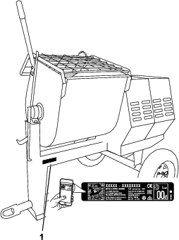
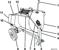
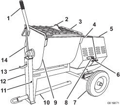
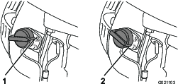
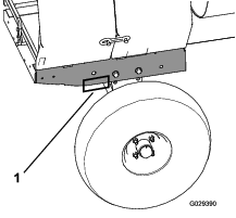
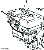
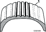
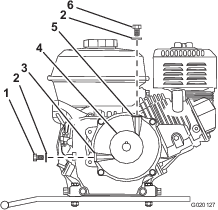
Whenever you need service, genuine Toro parts, or additional information, contact an Authorized Service Dealer or Toro Customer Service and have the model and serial numbers of your product ready. Figure 1 identifies the location of the model and serial numbers on the product. Write the numbers in the space provided.
Important: With your mobile device, you can scan the QR code on the serial number decal (if equipped) to access warranty, parts, and other product information.
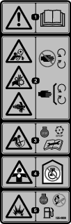
This manual identifies potential hazards and has safety messages identified by the safety-alert symbol (Figure 2), which signals a hazard that may cause serious injury or death if you do not follow the recommended precautions.

This manual uses 2 words to highlight information. Important calls attention to special mechanical information and Note emphasizes general information worthy of special attention.
It is a violation of California Public Resource Code Section 4442 or 4443 to use or operate the engine on any forest-covered, brush-covered, or grass-covered land unless the engine is equipped with a spark arrester, as defined in Section 4442, maintained in effective working order or the engine is constructed, equipped, and maintained for the prevention of fire.
The enclosed engine owner's manual is supplied for information regarding the US Environmental Protection Agency (EPA) and the California Emission Control Regulation of emission systems, maintenance, and warranty. Replacements may be ordered through the engine manufacturer.
Tire Information—The DOT tire information is located on the side of each tire. This information gives load and speed ratings. Replacement tires should have the same or better ratings; refer to Specifications to ensure that the tires on your machine meet or exceed the weight requirements of your machine.
Warning
CALIFORNIA
Proposition 65 Warning
The engine exhaust from this product contains chemicals known to the State of California to cause cancer, birth defects, or other reproductive harm.
Use of this product may cause exposure to chemicals known to the State of California to cause cancer, birth defects, or other reproductive harm.
Safety
Improper use or maintenance by the operator or owner can result in injury. To reduce the potential for injury, comply with these safety instructions and always pay attention to the safety-alert symbol (Figure 2), which means: Caution, Warning, or Danger—personal safety instruction. Failure to comply with the instruction may result in personal injury or death.
Safe Operating Practices
This product is capable of amputating hands. Always follow all safety instructions to avoid serious injury or death.
Warning
Machining or handling stone, masonry, concrete, metal, and other materials can generate dust, mists, and fumes containing chemicals, such as silica, known to cause serious or fatal injury or illness, such as respiratory disease, silicosis, cancer, birth defects, or other reproductive harm.
-
Control dust, mist, and fumes at the source where possible. Use water for dust suppression whenever possible.
-
Use good work practices and follow the recommendations of the manufacturer or suppliers, OSHA, and other occupational and trade associations.
-
Always follow respiratory precautions.
-
When you cannot eliminate the hazards from inhalation, you and all bystanders should wear a respirator approved by OSHA for the material that you are handling.
Warning
Engine exhaust contains carbon monoxide, which is lethal if inhaled.
Do not run the engine indoors or in an enclosed area.
Training
-
Park the machine on a level surface, shut off the engine, wait for all moving parts to stop, and allow the machine to cool before adjusting, cleaning, storing, or repairing the machine.
-
Read and understand the contents of this Operator’s Manual before you start the engine. Ensure that everyone using this product knows how to use it and understands the warnings.
-
Become familiar with the safe operation of the equipment, operator controls, and safety signs.
-
All operators and mechanics should be trained. The owner is responsible for training them.
-
Never let children or untrained people operate or service the equipment. Local regulations may restrict the age of the operator.
-
The owner/user can prevent and is responsible for accidents or injuries to people or damage to property.
Towing
-
Check with your local county or state towing safety regulations before towing the machine.
-
To reduce the possibility of an accident while transporting the machine on public roads, ensure that the towing vehicle is mechanically sound and in good operating condition.
-
Shut off the engine before transporting the machine.
-
When towing with a ball hitch, ensure that it is the proper size for the hitch coupler on the machine.
-
When towing with a pintle hitch, ensure that the eye of the tow pole is the correct dimension for the pintle hook.
-
Inspect the hitch and coupling for wear. Do not tow the machine with damaged or worn hitches, couplings, chains, or other components.
-
Check the air pressure of the tires on the towing vehicle and adjust the pressure as needed.
-
Check the tire tread and sidewall for damage and wear and replace the tire if necessary.
-
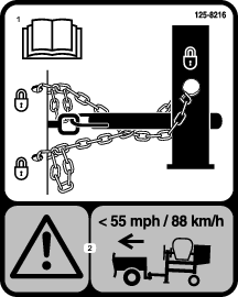
Properly attach the safety chains to the towing vehicle by crossing the chains and removing any extra slack.
-
Ensure that the directional and brake lights are working properly (if equipped).
-
Ensure that the directional, backup, and brake lights of the tow vehicle are working properly (if equipped).
-
Before towing, ensure that your machine is correctly and securely attached to the towing vehicle.
-
Ensure that the safety chains are properly secured to the vehicle, and leave enough slack for turning.
-
Do not carry any material in the machine when towing.
-
Avoid sudden stops and starts. This can cause skidding or jackknifing. Smooth, gradual starts and stops improves towing.
-
Avoid sharp turns to prevent rolling. Tow only with a vehicle that has a hitch designed for towing. Do not attach towed equipment except at the hitch point.
-
Do not tow the machine faster than 88 km/h (55 mph).
-
Use caution when backing up; use a spotter outside the vehicle to guide you.
-
Do not allow anyone to sit or ride on the machine.
-
Disconnect the machine from the tow vehicle before using it.
-
Place chocks underneath the tires to prevent them from rolling while the machine is parked.
Preparation
Become familiar with the safe operation of the equipment, operator controls, and safety signs.
-
Use only accessories and attachments approved by the manufacturer.
-
Wear personal protective equipment and appropriate clothing including:
-
Hard hat
-
Respirator or dust mask
-
Face shield
-
Safety glasses
-
Hearing protection
-
Safety shoes
-
Long pants
-
Shirt with long sleeves that are tight at the wrists
-
Tight-fitting gloves without drawstrings or loose cuffs
-
-
Wear appropriate clothing, including eye protection; long pants; substantial, slip-resistant footwear; and hearing protection. Tie back long hair and do not wear loose jewelry.
-
Ensure that the machine is on a level surface before operating it.
-
Chock the tires of the machine to prevent unintended movement.
-
Before every use, do the following:
-
Inspect the coupler, ball, and hitch.
-
Ensure that all lights are functioning properly (if equipped).
-
Ensure that the tires are properly inflated.
-
Ensure that the lug nuts are tight and torqued properly.
-
Ensure that the machine is properly secured.
-
Fuel Safety
-
Use extreme care in handling fuel. It is flammable and its vapors are explosive.
-
Extinguish all cigarettes, cigars, pipes, and other sources of ignition.
-
Use only an approved fuel container.
-
Do not remove the fuel cap or fill the fuel tank while the engine is running or hot.
-
Do not add or drain fuel in an enclosed space.
-
Do not store the machine or fuel container where there is an open flame, spark, or pilot light, such as on a water heater or other appliance.
-
If you spill fuel, do not attempt to start the engine; avoid creating any source of ignition until the fuel vapors have dissipated.
Operation
-
Use your full attention while operating the machine. Do not engage in any activity that causes distractions; otherwise, injury or property damage may occur.
-
Do not run an engine in an enclosed or poorly ventilated area.
-
Operate the machine only in good lighting conditions.
-
Before starting the machine, ensure that there are no people or obstacles near or under the machine.
-
Shut off the engine before leaving the machine for any reason.
Never leave a running machine unattended. Always shut off the engine and verify that all moving parts have stopped.
-
Chock the tires of the machine or keep it attached to the towing vehicle when it is not in use.
-
Keep your hands away from any moving parts. Keep your feet away from the tires and the front post.
-
Do not operate the machine under the influence of alcohol or drugs.
-
Do not place your hands or any solid object into the drum when the machine is in operation.
-
Do not touch parts that may be hot from operation. Allow them to cool before attempting to maintain, adjust, or service the machine.
-
Never move the machine while the engine is running.
-
Keep the cowl closed and latched during operation.
-
Ensure that all the guards and shields are securely in place before operating the machine.
-
If the mixing paddles strike an object or if the machine starts making an unusual noise or vibration, shut off the engine, wait for all moving parts to stop, and empty the drum. Inspect for clogging or damage. Clean, repair, and/or replace any damaged parts.
-
Do not change the engine governor setting or overspeed the engine.
-
Do not operate the machine when there is the risk of lightning.
Maintenance and Storage
-
Before performing maintenance, do the following:
-
Park the machine on a level surface.
-
Shut off the engine and wait for all movement to stop before adjusting, cleaning, or repairing the machine.
-
Let the engine cool before performing maintenance or storing the machine.
-
Disengage all power and operation controls.
-
-
Never lubricate, service, repair, or adjust the machine with the engine running.
-
Keep equipment materials clear from the muffler and engine to prevent fires. Clean up oil or fuel spills.
-
Never allow untrained personnel to service the machine.
-
Keep your hands, feet, and clothing away from moving parts. If possible, do not make adjustments with the engine running.
-
Keep all parts in good working condition and all fasteners tightened. Replace all worn or damaged decals.
-
Remove any buildup of grease, oil, or debris from the machine.
-
Stop and inspect the machine if an object enters the drum or causes another obstruction. Make all necessary repairs before starting the machine.
-
Do not tamper with safety devices.
-
Chock the tires when storing the machine.
-
Keep all fasteners and hose clamps securely tightened and all equipment in good condition.
-
Use only genuine Toro replacement parts.
Safety and Instructional Decals
|
Safety decals and instructions are easily visible to the operator and are located near any area of potential danger. Replace any decal that is damaged or lost. |


Setup
Installing the Dump Handle
Installing the Tow Pole
Parts needed for this procedure:
| Tow pole kit (sold separately) | 1 |
Tow Pole Specifications
Purchase the tow pole kit (including fasteners) that meets your needs from your Authorized Service Dealer. The machine has the following tow pole options:
| Hitch Type | Length |
|---|---|
| 50 mm (2 inch) ball—stamped | 78.7 cm (31 inches) or 127 cm (50 inches) |
| 50 mm (2 inch) ball—forged | 78.7 cm (31 inches) or 127 cm (50 inches) |
| Pintle | 78.7 cm (31 inches) or 127 cm (50 inches) |
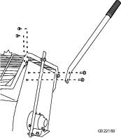
Installing the Tow Pole
-
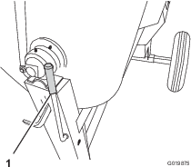
Remove the bolt and nut from the tow pole (Figure 6).
-
Slide the tow pole forward and align the hole in the pole with the hole in the frame fitting (Figure 6).
-
Insert the bolt through the holes in the fitting and the pole (Figure 6).
-
Thread the nut onto the bolt and tighten them until they are tight against the frame fitting (Figure 6).
Note: If the self-locking nylon insert in the locknut wears with use, replace the nut with a new Grade 5 or Grade 8 locknut.
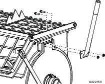
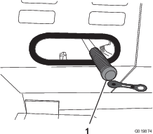
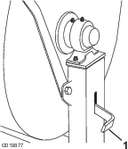
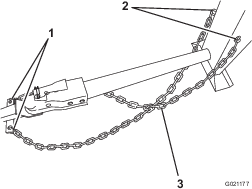
Installing the Safety Chain
Parts needed for this procedure:
| Safety chain (included with the tow pole kit) | 1 |
| Connecting link (included with the tow pole kit) | 2 |
Safety chain and connecting link are included in the tow pole kit (sold separately); refer to Installing the Tow Pole.
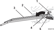
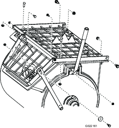
Form a hook on the end of a bendable piece of rod or stiff wire (not included) and install the safety chain and connecting links as shown in Figure 7.
Note: Ensure that approximately equal lengths of safety chain extend from either side of the front post.
Product Overview
Become familiar with all the controls before you start the engine and operate the machine.
Clutch Lever
Use the clutch lever to engage and disengage the paddles.
Drum Latch
Use the drum latch to secure the drum to the mix position (upright) for mixing operations and when transporting the machine.
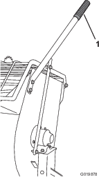
Dump Handle
Use the dump handle to rotate the drum to the dump position and to rotate the drum to the mix position (upright).
Engine Controls
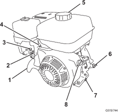
Fuel Valve
The fuel valve (Figure 16) is located underneath the choke lever. Move the lever for the fuel valve to the ON position before attempting to start the engine. When you have finished mixing, shut off the engine and move the fuel-valve lever to the OFF position.
Choke Lever
Use the choke lever (Figure 16) to start a cold engine. Before pulling the recoil-start handle, move the choke lever to the CLOSED position. Once the engine is running, move the choke lever to the OPEN position. Do not use the choke if the engine is already warmed up or if the air temperature is high.
Throttle Lever
The throttle lever (Figure 16) controls the speed (rpm) of the engine. It is located next to the choke lever. It sets the engine speed and therefore can increase and decrease the rotation speed of the mixing paddles. For best performance, set this control to the FAST position when mixing material.
Engine On/Off Switch
The On/Off switch is located on the front of the engine.
-
Rotate it to the ON position to start and run the engine.
-
Rotate it to the OFF position to shut off the engine.
Recoil-Start Handle
To start the engine, pull the recoil-start handle (Figure 15) quickly to turn the engine over. The engine controls described above must all be set correctly for the engine to start.
Oil-Level Switch
The oil-level switch is located inside the engine, and it does not allow the engine to run in the event the oil level is below the safe operating limit.
Note: Specifications and design are subject to change without notice.
| Model | 68013 | 68014 | 68016 | 68017 | 68020 | 68021 | 68024 |
| Batch Capacity | 0.17 m3 (6.0 ft3) | 0.17 m3 (6.0 ft3) | 0.17 m3 (6.0 ft3) | 0.17 m3 (6.0 ft3) | 0.23 m3(8.0 ft3) | 0.23 m3 (8.0 ft3) | 0.34 m3 (12.0 ft3) |
| Total Volume | 0.20 m3 (6.9 ft3) | 0.20 m3 (6.9 ft3) | 0.20 m3 (6.9 ft3) | 0.20 m3 (6.9 ft3) | 0.25 m3 (9.0 ft3) | 0.25 m3 (9.0 ft3) | 0.42 m3 (14.8 ft3) |
| Drum Material | Steel | Polyethylene | Steel | Polyethylene | Steel | Polyethylene | Steel |
| Length (without tow pole) | 163 cm (64 inches) | 163 cm (64 inches) | 163 cm (64 inches) | 163 cm (64 inches) | 193 cm (86 inches) | 193 cm (86 inches) | 205.7 cm (81 inches) |
| Width | 86 cm (34 inches) | 86 cm (34 inches) | 86 cm (34 inches) | 86 cm (34 inches) | 86 cm (34 inches) | 86 cm (34 inches) | 142.2 cm (50 inches) |
| Height | 137 cm (54 inches) | 137 cm (54 inches) | 137 cm (54 inches) | 137 cm (54 inches) | 137 cm (54 inches) | 137 cm 0(54 inches) | 150 cm (59 inches) |
| Weight | 250 kg (550 lb) | 241 kg (530 lb) | 250 kg (550 lb) | 241 kg (530 lb) | 275 kg (605 lb) | 266 kg (585 lb) | 508 kg (1120 lb) |
| Axle | 86 to 117 cm (34 to 46 inches)extendable | 86 to 117 cm (34 to 46 inches)extendable | 86 to 117 cm (34 to 46 inches)extendable | 86 to 117 cm (34 to 46 inches)extendable | 86 to 117 cm (34 to 46 inches)extendable | 86 to 117 cm (34 to 46 inches)extendable | 142 cm (56 inches)fixed |
| Engine | Honda® GX160 | Honda® GX160 | Honda® GX240 | Honda® GX240 | Honda® GX240 | Honda® GX240 | Honda® GX340 |
| Drive | Belt | Belt | Belt | Belt | Belt | Belt | Gearbox |
Operation
Important: Before operating, check the fuel and oil levels, and remove debris from the machine. Ensure that the area is clear of people.
Think Safety First
Carefully read all safety instructions and symbols in this manual, on the product decals, and other media supplied with the product. Knowing this information could help you or bystanders avoid injury.
Know how to quickly shut down the machine in an emergency.
Use a hard-hat, hearing protection, a shirt with long sleeves that are tight at the wrists, tight-fitting gloves without drawstrings or loose cuffs, eye protection, and a dust mask or respirator. A mesh visor alone does not provide sufficient eye protection; supplement with protective glasses.
Caution
This machine produces sound levels that can cause hearing loss through extended periods of exposure.
Wear hearing protection when operating this machine.

Towing the Machine
Before towing the machine, read all the information and perform all the applicable procedures to in this section to ensure safe and proper towing.
Warning
Towing the machine at high speed increases the risk of a hitch malfunction and tire failure. Higher speeds also increase the momentum of the machine and braking distance. If the machine detaches from the tow vehicle at high speed, it could cause damage to property, or injury or death to bystanders.
Do not exceed 88 km/h (55 mph) when towing the machine. For poor road conditions or inclement weather, reduce speed accordingly.
Warning
Towing the machine with material in the drum increases the risk of a hitch malfunction and tire failure. In addition, material could bounce out of the drum and hit other vehicles and/or people. Material in the drum increases the weight, which affects momentum and braking distance.
Do not tow the machine with material in the drum.
-
Review and understand the Safe Operating Practices.
-
Test the brakes of the tow vehicle before towing.
-
Avoid sudden starts and stops while towing the machine.
Tow Vehicle Requirements
Before connecting the machine to your tow vehicle, ensure that your vehicle is prepared as follows:
-
Ensure that your tow vehicle has towing capacity for the weight of the machine; refer to Specifications.
-
Use a Class 2 or larger receiver.
-
Ensure that your tow vehicle has the appropriate hitch to tow the machine; options include a 50 mm (2 inch) ball hitch or a pintle hitch.
-
If the machine is equipped with a trailer-light kit, ensure that the electrical connector of the tow vehicle is compatible with the electrical connector of the machine. The machine uses a standard 4-pin, flat plug. If your tow vehicle has a different type of plug, obtain an adapter from an automotive parts store.
Preparing the Machine for Towing
-
Shut off the engine and fuel valve.
-
Empty the drum.
-
Position the drum in the mix position (upright) and lock it.
-
Close the engine cowl and secure the cowl latches (Figure 19).
-
If you have adjusted the axle to the narrow position (if equipped on your model), extend the axle; refer to Adjusting the Axle Width.
-
Inspect the tires; refer to Inspecting the Tires.
Hitching the Machine to a Tow Vehicle
Your machine is equipped with 1 of the following hitch types; hitch it as described in the appropriate procedure:
-
Stamped-ball coupler—Hitching a Stamped-Ball Coupler
-
Forged-ball coupler—Hitching a Forged-Ball Coupler
-
Pintle-hitch coupler—Hitching a Pintle-Hitch Coupler
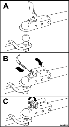
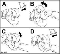
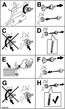
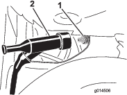
Hitching a Stamped-Ball Coupler
-
Apply chassis grease to the socket of the coupler and the area of the clamp that contacts the ball.
-
Oil the pivot points and sliding surfaces of the coupler with SAE 30 motor oil.
-
Hitch the machine as shown in Figure 20.
Hitching a Forged-Ball Coupler
-
Apply removable thread-locking compound to the threads of the coupler bolt to prevent the coupler handle from coming loose.
Important: Apply thread-locking compound as needed in the future.
-
Apply chassis grease to the socket of the coupler and the area of the clamp that contacts the ball.
-
Hitch the machine as shown in Figure 21.
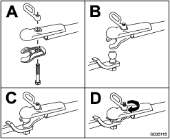
Note: Use a wrench to keep the bolt from spinning.
Hitching a Pintle-Hitch Coupler
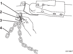
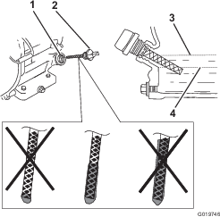
Connecting the Safety Chains to the Tow Vehicle
-
Pull the safety chain through the slots in the keyholes, so that the lengths on each side are equal.
-
Cross both lengths of chain under the tow pole.
Note: Crossing the chains decreases the chances of the front of the machine dropping to the ground if the hitch does not hold the connection.
-
Connect each length of chain to the safety chain mounting point on the tow vehicle with the connecting links (Figure 24).
Important: Ensure that the chain has enough slack for turning around corners when towing the machine.
Note: Stow the excess chain inside the bottom of the front post by pushing it into the keyholes and latching the appropriate links into the keyhole slots.
Connecting and Checking the Lights
Machines Equipped with a Light Kit Only
-
Connect the electrical plug of the machine with the electrical plug of the tow vehicle (Figure 27).
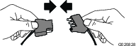
Note: The machine uses a standard 4-pin, flat plug. If your tow vehicle has a different type of plug, obtain an adapter from an automotive parts store.
-
Ensure that the tow vehicle is in the NEUTRAL position, engage the parking brake, and start the engine.
-
Test the lights as follows:
-
Turn on the headlights of the tow vehicle.
The tail lights of the machine should illuminate.
-
Press the brake pedal of the tow vehicle.
The brake lights of the machine should illuminate.
-
Operate each turn signal of the tow vehicle in turn.
The corresponding turn-signal lights of the machine should illuminate.
-
Adjusting the Axle Width
Models with Adjustable Axles Only
If your model is equipped with an adjustable axle (Figure 27), you can adjust the axle to the narrow position to move the machine through a narrow access point, such as the gate of a fence or the doorway of a building.
Warning
The machine is not stable when towed with the axle in the narrow position.
Tow the machine with the axle in the wide position.
Important: The machine is less stable with the axle in the narrow position. Only adjust it to the narrow position when necessary to move past an obstruction, then return it to the wide position before towing or operating the machine.
-
Park the machine on a level surface and disconnect the machine from the tow vehicle.
-
Secure the machine from movement.
-
Empty the drum, move it to the upright position, and lock the drum.
-
Align a jack with an adequate lift height and weight capacity under the axle; refer to Specifications.
-
Lift the machine until the tires are off the ground.
-
Use a jack stand at each support point on the rear frame extension (Figure 26).
Warning
Mechanical or hydraulic jacks may fail to support the machine and cause serious injury.
Use jack stands when supporting the machine.
-
Remove the bolts and nuts that secure the inner axle to the outer axle (Figure 27).
-
Align the inner axle to the desired position as follows:
-
Secure the axle with the bolts and nuts removed previously (Figure 27) and torque them to 87 N∙m (64 ft-lb).
Preparing to Use the Machine
-
Park the machine on a level surface and disconnect the machine from the tow vehicle.
-
Ensure that all guards and paddles are in place and in good condition.
-
Perform all daily maintenance procedures prescribed in .
-
Chock the front and back of the tires to prevent the machine from moving.
-
Move the drum to the upright position and lock it.
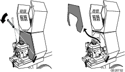
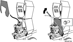
Opening the Cowl
Closing the Cowl
Adding Fuel
Danger
In certain conditions, fuel is extremely flammable and highly explosive. A fire or explosion from fuel can burn you and others and can damage property.
-
Fill the fuel tanks outdoors, in an open area, when the engine is cold. Wipe up any fuel that spills.
-
Never fill the fuel tanks inside an enclosed trailer.
-
Never smoke when handling fuel and stay away from an open flame or where fuel fumes may be ignited by a spark.
-
Store fuel in an approved container and keep it out of the reach of children. Never buy more than a 30-day supply of fuel.
-
Do not operate without entire exhaust system in place and in proper working condition.
Danger
In certain conditions during fueling, static electricity can be released, causing a spark that can ignite the fuel vapors. A fire or explosion from fuel can burn you and others and can damage property.
-
Always place fuel containers on the ground away from your vehicle before filling.
-
Do not fill fuel containers inside a vehicle or on a truck or trailer bed, because interior carpets or plastic truck bed liners may insulate the container and slow the loss of any static charge.
-
When practical, remove equipment from the truck or trailer and refuel the equipment with its wheels on the ground.
-
If this is not possible, then refuel such equipment on a truck or trailer from a portable container rather than from a fuel-dispenser nozzle.
-
If you must use a fuel-dispenser nozzle, keep the nozzle in contact with the rim of the fuel tank or container opening at all times until fueling is complete.
Warning
Fuel is harmful or fatal if swallowed. Long-term exposure to vapors can cause serious injury and illness.
-
Avoid prolonged breathing of vapors.
-
Keep your face away from the nozzle and fuel tank opening.
-
Keep fuel away from your eyes and skin.
Fuel Recommendations
-
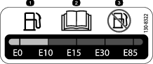
For best results, use only clean, fresh (less than 30 days old), unleaded gasoline with an octane rating of 87 or higher ((R+M)/2 rating method).
-
Ethanol: Gasoline with up to 10% ethanol (gasohol) or 15% MTBE (methyl tertiary butyl ether) by volume is acceptable. Ethanol and MTBE are not the same. Gasoline with 15% ethanol (E15) by volume is not approved for use. Never use gasoline that contains more than 10% ethanol by volume, such as E15 (contains 15% ethanol), E20 (contains 20% ethanol), or E85 (contains up to 85% ethanol). Using unapproved gasoline may cause performance problems and/or engine damage which may not be covered under warranty.
-
Do not use gasoline containing methanol.
-
Do not store fuel either in the fuel tank or in fuel containers over the winter unless you use a fuel stabilizer.
-
Do not add oil to gasoline.
Important: To reduce starting problems, add fuel stabilizer to the fuel all season, mixing it with fuel less than 30 days old; run the machine dry before storing it for more than 30 days.Do not use fuel additives other than a fuel stabilizer/conditioner. Do not use fuel stabilizers with an alcohol base such as ethanol, methanol, or isopropanol.
Fuel Tank Capacity
| Model | Fuel Tank Capacity |
|---|---|
| 68013 and 68014 | 3.1 L (0.82 US gallons) |
| 68016, 68017, 68020, 68021 | 5.3 L (1.40 US gallons) |
| 68024 | 6.1 L (1.61 US gallons) |
Filling the Fuel Tank
-
Park the machine on a level surface, shut off the engine, and allow the engine to cool.
-
Clean around the fuel cap and remove it (Figure 30).
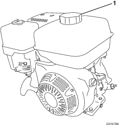
-
Add fuel to the fuel tank until the level is at the maximum fuel level (Figure 31).
Important: This space in the tank allows fuel to expand. Do not fill the fuel tank completely full.
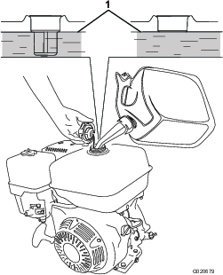
-
Install the fuel cap securely (Figure 30).
-
Wipe up any spilled fuel.
Performing Daily Maintenance
Before starting the machine each day, perform the Each Use/Daily procedures listed in .
Starting the Engine
-
Ensure that the clutch lever is in the OFF position.
-
Move the fuel valve to the OPEN position, all the way to the right (Figure 32).
-
Move the choke lever to the ON position (Figure 32).
Note: A warm or hot engine may not require choking.
-
Move the throttle lever 1/3 of the way toward the MAX position.
-
Move the engine switch to the ON position (Figure 33).
-
Pull the starter handle lightly until you feel resistance, then pull the handle briskly (Figure 34). Return the starter handle gently.
-
After the engine starts, gradually move the choke lever back to the OFF position. If the engine stalls or hesitates, move the choke back to the ON position again until the engine warms up. Then move it to the OFF position.
Shutting Off the Engine
-
Move the throttle lever to the MIN position (Figure 15).
Note: If the engine has been working hard or is hot, let it idle for a minute before shutting off the engine. This helps to cool the engine before stopping. In an emergency, shut off the engine immediately.
-
Move the engine switch to the OFF position.
-
Move the fuel valve to the CLOSED position, all the way to the left.
Mixing the Material
Danger
Eye and skin contact with concrete materials and breathing the dust involved is hazardous to your health.
-
Ensure that there is adequate air ventilation.
-
Wear a dust mask to prevent inhalation of dust while using the machine; refer to Safe Operating Practices.
-
Avoid direct contact of cement and concrete materials with skin and eyes.
Danger
This machine is capable of amputating hands.
-
Stay in the operator’s position while the machine is running.
-
Keep all bystanders a safe distance away from the machine.
-
Stop the machine immediately if any people or animals enter the work area.
-
Never place any part of your body into a position that causes an unsafe operating condition.
Important: Do not add more material than the batch capacity of the machine; refer to Specifications.
Note: Follow the manufacturer’s instructions that are printed on the packaging of the product you are using.
-
Ensure that there is no old, loose material in the drum that can contaminate the batch of material; refer to Cleaning the Drum and Dumping the Material, then return the drum to the upright position.
Note: Ensure that the drum is in the mix position (upright) and the drum latch is engaged.
-
Move the clutch lever to the OFF position (Figure 35 or Figure 36).
-
Start the engine.
Note: Allow the engine to warm up at 2/3 throttle for 1 to 2 minutes.
-
Set the throttle lever on the engine to the MAX position.
-
Move the clutch lever to the ON position (Figure 35 or Figure 36).
-
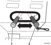
Add the ingredients for the batch as follows:
-
Pour water into the drum through the grate.
-
Add the plaster, cement, or other binding material.
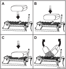
Note: You can open bags of cement, plaster, and binding materials by lowering the bag onto the bag splitter (Figure 37).
-
If you are using sand and/or other reinforcing materials, add them into the drum.
-
-
Allow the paddles to mix the material until the ingredients have a uniform appearance.
Note: If needed, add water or plaster, cement, or other binding material until the consistency of the batch is correct.
Dumping the Material
Danger
Contact with the mixing paddles could cause damage or injury.
Never put your hands inside the drum while the engine is running.
Note: When dumping a batch of material, leave the engine/motor running and the clutch in the ON position so that the rotating paddles help discharge the material.
-
Align a wheelbarrow or similar container of adequate capacity in the path of the drum opening.
-
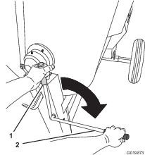
Grasp the dump handle with your left hand (Figure 38).
-
Lift the handle of the drum latch (Figure 38).
-
With both hands on the dump handle, rotate it counterclockwise to discharge the contents of the drum (Figure 38).
Note: Allow the machine to completely discharge the contents of the drum.
-
Rotate the dump handle clockwise until the drum latch locks the drum in the upright position (Figure 38).
-
After dumping a batch of material, clean the drum to prevent dried material from contaminating the next batch of material; refer to Cleaning the Drum.
Cleaning the Drum
Important: Do not strike on the drum with a shovel, hammer, or any other device to loosen any accumulated dried materials.
-
Move the clutch lever to the OFF position to stop the paddles.
-
Shut off the engine/motor.
-
Ensure that the drum is in the mix position (upright).
-
Spray the machine with water to remove any accumulated material.
-
Start the engine/motor.
-
Move the clutch lever to the ON position to start the paddles.
-
Dump the drum.
Maintenance
Warning
Failure to properly maintain the machine could result in premature failure of machine systems causing possible harm to you or bystanders.
Keep the machine well maintained and in good working order as indicated in these instructions.
Important: Refer to your engine operator's manual for additional maintenance procedures.
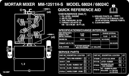
Recommended Maintenance Schedule(s)
| Maintenance Service Interval | Maintenance Procedure |
|---|---|
| After the first 20 hours |
|
| After the first 25 hours |
|
| Before each use or daily |
|
| After each use |
|
| Every 40 hours |
|
| Every 50 hours |
|
| Every 100 hours |
|
| Every 300 hours |
|
| Every 800 hours |
|
| Monthly |
|
| Yearly or before storage |
|
| Every 2 years |
|
Pre-Maintenance Procedures
Preparing the Machine for Maintenance
-
Shut off the engine and allow it to cool completely.
-
Park the machine on a level surface.
-
Remove the machine from the tow vehicle.
-
Secure the machine from movement.
-
Disconnect the spark-plug wire.
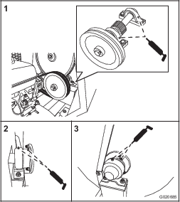
Disconnecting the Spark-Plug Wire
Pull the spark-plug wire off the terminal of the spark plug (Figure 39).
Removing the Divider Plate
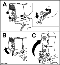
If your model has a divider plate, you may need to remove it before performing some maintenance procedures:
-
Open the cowl.
-
Use a wrench to remove the 4 bolts that secure the divider plate to the front cowl.
Note: Retain the fasteners for installing the divider plate.
-
To remove the divider plate, lift it upward and tilt it back so that it clears various components.
Installing the Divider Plate
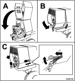
When finished performing maintenance, install the divider plate as follows:
-
Guide the divider plate into position against the front cowl.
Note: Start with the divider plate rotated slightly counterclockwise, and then rotate it clockwise while lowering it into position. Ensure that the divider plate is not backward.
-
Align the bolt holes in the divider plate and the front cowl.
-
Install each of the 4 bolts, and hand-tighten them to prevent cross-threading.
-
Tighten the bolts with a wrench until they are secure.
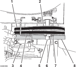
Lubrication
Lubricating the Bearings and Seals
| Maintenance Service Interval | Maintenance Procedure |
|---|---|
| After each use |
|
| Monthly |
|
Note: The pillow-block bearings are inside the cowl—remove the divider plate if equipped) to access them; refer to Removing the Divider Plate.
Grease Type: No. 2 lithium grease.
-
Complete the procedures listed in Preparing the Machine for Maintenance.
-
Clean the area around each grease fitting with a rag and lift the plastic cap off the grease fitting (Figure 42).
-
Pump grease into each fitting as follows:
-
For the pillow-block bearings, pump 1 shot of grease into each fitting (Figure 42).
-
For the trunnions, pump several shots of grease into each fitting until it starts to ooze out of the bearing housing (Figure 42).
Important: Pump grease in slowly and carefully to prevent damage to the bearing seals.
-
-
Wipe up any excess grease.
Engine Maintenance
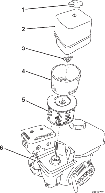
Servicing the Air Cleaner
| Maintenance Service Interval | Maintenance Procedure |
|---|---|
| Before each use or daily |
|
| Every 50 hours |
|
| Every 300 hours |
|
Important: Do not operate the engine without the air-filter assembly; extreme engine damage will occur.
-
Shut off the engine and wait for all moving parts to stop.
-
Disconnect the wire from the spark plug; refer to Disconnecting the Spark-Plug Wire.
-
Remove the nut that secures the cover (Figure 43).
-
Remove the cover.
Note: Be careful to prevent dirt and debris from falling into the base.
-
Remove the foam and paper elements from the base (Figure 43).
-
Remove the foam element from the paper element (Figure 43).
-
Inspect the foam and paper elements and replace them if they are damaged or excessively dirty.
Note: Never try to brush dirt off the paper element; brushing forces the dirt into the fibers.
-
Clean the foam element in warm, soapy water or in a nonflammable solvent.
Note: Do not use fuel to clean the foam element because it could create a risk of fire or explosion.
-
Rinse and dry the foam element thoroughly.
-
Dip the foam element in clean engine oil, then squeeze out the excess oil.
Note: Excess oil in the foam element restricts the air flow through the element and may reach the paper filter and clog it.
-
Wipe dirt from the base and the cover with a moist rag.
Note: Be careful to prevent dirt and debris from entering the air duct leading to the carburetor.
-
Install the air-cleaner elements and ensure that they are properly positioned.
-
Securely install the cover with the nut.
Servicing the Engine Oil
Engine-Oil Specifications
Toro Premium Engine Oil is available from your Authorized Toro Dealer.
Important: Use 4-cycle engine oil that meets or exceeds the requirements for API service category SJ, SL, SM, or higher.
| Model(s) | Crankcase Capacity |
|---|---|
| 68013 and 68014 | 0.58 L (0.61 US qt) |
| 68016, 68017, 68020, 68021, 68024 | 1.1 L (1.2 US qt) |
Important: If the oil level in the crankcase is too low or too high and you run the engine, you may damage the engine. This type of damage is not covered by the warranty.
Note: Use SAE 10W-30 for general use. You can use the other viscosities shown in the chart when the average temperature in your area is within the indicated range (Figure 44).
Checking the Engine-Oil Level
| Maintenance Service Interval | Maintenance Procedure |
|---|---|
| Before each use or daily |
|
-
Park the machine on a level surface and shut off the engine.
-
Allow the engine to cool.
-
Disconnect the wire from the spark plug; refer to Disconnecting the Spark-Plug Wire.
-
Clean around the dipstick.
-
Check the oil level as shown in Figure 45.
Changing the Engine Oil
| Maintenance Service Interval | Maintenance Procedure |
|---|---|
| After the first 25 hours |
|
| Every 100 hours |
|
Warning
Oil may be hot after the engine has been run, and contact with hot oil can cause severe personal injury.
Avoid contacting the hot engine oil when you drain it.
-
Shut off the engine and wait for all moving parts to stop.
-
Disconnect the wire from the spark plug; refer to Disconnecting the Spark-Plug Wire.
-
Place a drain pan under the oil-drain hole of the engine (Figure 46).
-
Remove the drain plug and catch the oil in the oil-drain pan (Figure 46).
-
When the oil has drained completely, install the drain plug with a new washer (Figure 46).
Note: Dispose of the used oil at a certified recycling center.
-
Remove the dipstick (Figure 47) and slowly pour oil into the fill hole until the oil reaches the upper-limit mark (bottom edge of the oil-fill hole) on the dipstick.
-
Replace and secure the dipstick.
-
Wipe up any spilled oil.
Servicing the Spark Plug
| Maintenance Service Interval | Maintenance Procedure |
|---|---|
| Every 100 hours |
|
| Every 300 hours |
|
Spark Plug Specifications
Type: NGK BPR6ES or equivalent
Gap: 0.7 to 0.8 mm (0.028 to 0.031 inch)
Note: Use a 21 mm (13/16 inch) spark-plug wrench for removing and installing the spark plug.
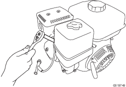
Removing the Spark Plug
-
Park the machine on a level surface and shut off the engine.
-
Ensure that the machine surfaces are cool.
-
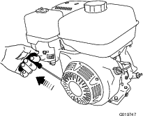
Pull the spark-plug wire off the terminal of the spark plug (Figure 48).
-
Clean around the spark plug.
-
Rotate the spark plug counterclockwise using a 21 mm (13/16 inch) spark-plug wrench to remove the plug and the sealing washer (Figure 49).
Checking the Spark Plug
Important: Do not clean the spark plug. Always replace the spark plug when it has a black coating, worn electrodes, an oily film, or cracks.
Note: If you see light brown or gray on the insulator, the engine is operating properly. A black coating on the insulator usually means that the air cleaner is dirty.
Set the gap to 0.7 to 0.8 mm (0.028 to 0.031 inch).
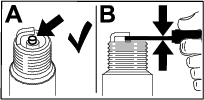
Installing the Spark Plug
Important: Ensure that the gap between the side and center electrodes is correct before installing the spark plug.
-
Thread the spark plug clockwise into the spark-plug hole by hand.
Note: Avoid cross-threading the spark plug with the threads of the spark-plug hole.
-
Rotate the spark plug clockwise using a 21 mm (13/16 inch) spark-plug wrench until the plug and sealing washer are seated (Figure 49).
-
Tighten the spark plug as follows:
-
When installing an in-service spark plug, tighten the plug an additional 1/8 to 1/4 turn.
-
When installing a new spark plug, tighten the plug an additional 1/2 turn.
Important: A loose spark plug may cause the cylinder to overheat. An over-tight spark plug may damage the threads in the cylinder head.
-
-
Push the spark-plug wire onto the terminal of the spark plug (Figure 48).
Cleaning the Spark Arrester
| Maintenance Service Interval | Maintenance Procedure |
|---|---|
| Every 100 hours |
|
Note: A spark arrester is available as an option. If you require a spark arrester, contact your Authorized Service Dealer. Genuine Toro spark arresters are approved by the USDA Forestry Service.
Warning
If the engine has been running, the muffler will be hot. Contact with hot surfaces may cause personal injury.
Keep your hands, feet, face, clothing and other body parts away from the muffler and other hot surfaces until they have cooled.
-
Park the machine on a level surface and shut off the engine.
-
Allow the engine to cool.
-
Disconnect the wire from the spark plug; refer to Disconnecting the Spark-Plug Wire.
-
Remove the divider plate (if equipped); refer to Removing the Divider Plate.
-
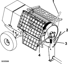
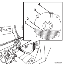
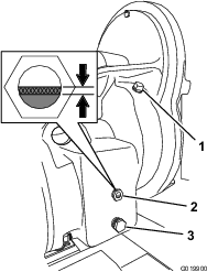
Remove the 2 nuts (8 mm) and remove the muffler from the cylinder (Figure 51).
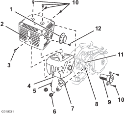
-
Remove the 3 screws (4 mm) from the exhaust deflector, and remove the deflector (Figure 51).
-
Remove the screws (5 mm and 6 mm) from the muffler protector, and remove the muffler protector (Figure 51).
-
Remove the screws (4 mm) from the spark arrester, and remove the spark arrester from the muffler (Figure 51).
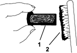
-
Use a brush to carefully remove carbon deposits from the spark-arrester screen (Figure 52).
Note: Replace the spark arrester if it has breaks or holes.
-
Install the spark arrester, muffler protector, exhaust deflector, and muffler in the reverse order of disassembly.
-
Install the divider plate (if equipped); refer to Installing the Divider Plate.
Removing and Installing the Engine
Belt-Drive Models Only
Removing the Engine
Warning
The spring is under tension when installed and can cause personal injury.
Be careful when removing the spring.
-
Park the machine on a level surface and shut off the engine.
-
Allow the engine to cool.
-
Disconnect the wire from the spark plug; refer to Disconnecting the Spark-Plug Wire.
-
Remove the divider plate; refer to Removing the Divider Plate.
-
Remove the belt guide; refer to Removing the Belts.
-
Remove the belts; refer to Removing the Belts.
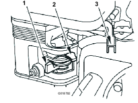
-
Using a spring-removal tool (Toro Part No. 92-5771), remove the spring from the anchor bracket on the engine deck (Figure 53).
Note: Leave the other end of the spring attached to the frame of the machine.
-
Remove the bolt and nut that secure the rear bracket for the engine deck hinge to the frame of the machine (Figure 54).
-
Lift up the rear edge of the engine deck and remove the hinge bracket (Figure 54).
-
Slide the engine deck rearward and out from the forward hinge bracket (Figure 55).
Note: Do not remove the forward hinge bracket.

-
Remove the engine and engine deck from the machine (Figure 55).
Installing the Engine
-
Align the engine and engine deck to the rear frame of the machine.
Note: The drive pulley on the engine must align forward.
-
Align the pivot on the engine deck with the forward hinge bracket (Figure 55).
-
Slide the engine deck forward and the pivot into the forward hinge bracket (Figure 55).
-
Align the rear hinge bracket with the pivot on the engine-deck hinge (Figure 55).
-
Lift up on the rear edge of the engine deck and slip the hinge bracket onto the pivot.
-
Secure the rear bracket to the frame of the machine using the bolt and nut (Figure 54) removed in step 8 of Removing the Engine.
-
Using a spring-removal tool (Toro Part No. 92-5771), install the tension spring to the anchor bracket on the engine deck (Figure 53).
-
Install the belts and belt guide; refer to Installing the Belts.
-
Adjust the belt guide; refer to Adjusting the Belt Guide.
-
Install the divider plate; refer to Installing the Divider Plate.
Fuel System Maintenance
Cleaning the Fuel-Sediment Cup
| Maintenance Service Interval | Maintenance Procedure |
|---|---|
| Every 100 hours |
|
| Yearly or before storage |
|
Underneath the fuel valve is a sediment cup to catch dirt in the fuel.
-
Park the machine on a level surface and shut off the engine.
-
Allow the engine to cool.
-
Disconnect the wire from the spark plug; refer to Disconnecting the Spark-Plug Wire.
-
Move the lever of the fuel valve to the OFF position, all the way to the left (Figure 56).
-
Unscrew the fuel-sediment cup (Figure 56).
-
Remove and retain the fuel filter and O-ring (Figure 56).
Note: Do not clean the O-ring in solvent.
-
Clean the fuel filter and sediment cup using a nonflammable solvent, and dry it carefully.
-
Wipe the O-ring with a clean, dry cloth.
-
Install the fuel filter in the bottom of the carburetor (Figure 56).
-
Align the O-ring in to the groove in the sediment cup and install the sediment cup to the fuel-valve housing.
-
Move the lever of the fuel valve to the ON position (all the way to the right) and check for leaks. If it leaks, replace the O-ring.
Draining the Fuel Tank
-
Remove the engine; refer to Removing the Engine.
-
Remove the fuel cap by rotating it counterclockwise (Figure 57).
-
Align a drain pan to the hinge of the engine deck.
-
Rotate the engine on the hinge side of the engine deck and drain the fuel from the tank (Figure 58).
-
Carefully lower the engine and engine deck.
-
Install the fuel cap.
-
Install the engine; refer to Installing the Engine.
Drive System Maintenance
Tire Air Pressure
The following table shows the appropriate air pressure for the tires as installed at the factory.
Important: Always check the information on the actual tires for the correct air pressure requirement.
| Model | Maximum Air Pressure |
|---|---|
| 68013, 68014, 68016, and 68017 | 414 kPa (60 psi) |
| 68020, 68021, and 68024 | 241 kPa (35 psi) |
Inspecting the Tires
| Maintenance Service Interval | Maintenance Procedure |
|---|---|
| Before each use or daily |
|
Warning
Failure to maintain correct tire pressure may result in tire failure and loss of control, resulting in property damage and serious injury or death.
-
Check the tire pressure frequently to ensure proper inflation. If the tires are not inflated to the correct pressure, they will wear prematurely.
-
Inspect the tire condition before towing and after any operating accident.
The DOT tire information is located on the side of each tire. This information gives load and speed ratings. Replacement tires should have the same or better ratings
Note: Ensure that any tires installed on your machine meet or exceed the weight requirements of your machine as listed in Specifications.
-
Visually inspect the tires for damage and wear (Figure 59 and Figure 60).
-
Ensure that the tires are inflated to the correct air pressure; refer to Tire Air Pressure.
Important: The most common cause of tire trouble is under-inflation. Maintain full air pressure.
Torquing the Wheel Lug Nuts
| Maintenance Service Interval | Maintenance Procedure |
|---|---|
| After each use |
|
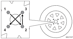
Torque the wheel lug nuts initially and after towing.
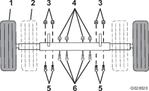
Torque the wheel lug nuts 108 to 122 N∙m (80 to 90 ft-lb), in the sequence shown in Figure 61.
Servicing the Reduction Case
Models 68013 and 68014 Only
Important: If the oil level in the reduction case is too low or too high and you run the engine, you may damage the engine or the reduction case. This type of damage is not covered by the warranty.
Reduction-Case Oil Specifications
Oil type: 4-cycle, SAE 10W-30 motor oil
Oil API service category: SJ, SL, SM, or higher
Reduction-case capacity: 1.2 L (40 fl oz)
Checking the Reduction-Case Oil
| Maintenance Service Interval | Maintenance Procedure |
|---|---|
| Before each use or daily |
|
-
Park the machine on a level surface and shut off the engine.
-
Allow the engine to cool.
-
Disconnect the wire from the spark plug; refer to Disconnecting the Spark-Plug Wire.
-
Remove the divider plate; refer to Removing the Divider Plate.
-
Locate the reduction case between the engine and the engine pulley (Figure 62).
-
Align a rag below the oil-level port in the side of the reduction case.
-
Remove the oil-level-check bolt and washer from the oil-level port (Figure 62).
-
If the oil level is below the threads in the oil-level port, add oil as follows:
-
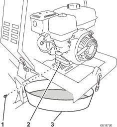
Remove the filler bolt and washer from the filler port on the top of the reduction case (Figure 62).
-
Slowly pour the specified oil into the fill port until the oil level is level with the threads at the bottom of the oil-level port.
-
Install the filler bolt and the washer to the filler port of the reduction case, and tighten the filler bolt (Figure 62).
-
-
If the oil level is too high, allow the oil to flow out until it is flush with the threads at the bottom of the oil-level port.
-
-
When the oil is level is flush with the threads at the bottom of the oil-level port, install the oil-level-check bolt and washer to the port, and tighten the bolt (Figure 62).
-
Install the divider plate; refer to Installing the Divider Plate.
Changing the Reduction-Case Oil
| Maintenance Service Interval | Maintenance Procedure |
|---|---|
| After the first 20 hours |
|
| Every 100 hours |
|
-
Park the machine on a level surface and shut off the engine.
-
Allow the engine to cool.
-
Disconnect the wire from the spark plug; refer to Disconnecting the Spark-Plug Wire.
-
Remove the engine; refer to Removing the Engine.
-
Drain the fuel tank; refer to Draining the Fuel Tank.
-
Remove the filler bolt and washer from the filler port on the top of the reduction case (Figure 63).
-
Remove the oil-level-check bolt and washer from the oil-level port in the side of the reduction case (Figure 63).
-
Align a drain pan to the hinge of the engine deck (Figure 64).
-
Rotate the engine on the hinge side of the engine deck, and drain the oil from the reduction case (Figure 64).
-
Carefully lower the engine and engine deck.
-
Slowly pour the specified oil into the fill port until the oil level is level with the threads at the bottom of the oil-level port (Figure 62).
-
Install the oil-level-check bolt and washer to the oil-level port of the reduction case, and tighten the bolt (Figure 63).
-
Install the filler bolt and washer to the filler port of the reduction case and tighten the filler bolt (Figure 63).
-
Install the engine; refer to Installing the Engine.
Servicing the Gearbox
Gearbox Models Only
Checking the Clutch Operation
| Maintenance Service Interval | Maintenance Procedure |
|---|---|
| After the first 25 hours |
|
| Before each use or daily |
|
Important: Check the gearbox clutch if the paddles rotate when the clutch lever is in the OFF position, if the paddles rotate slowly, or if the clutch begins to slip.
-
Move the clutch lever to the OFF position.
-
Start the engine.
-
Ensure that the engine throttle is set to the 2/3 position.
-
If the paddles rotate with the clutch lever to the OFF position do the following:
-
Shut off the engine.
-
Locate the clutch lever at the back of the machine; refer to Clutch Lever.
-
Move the clutch lever to the OFF position.
-
Attach a spring scale with a range of 15 to 30 kg (35 to 55 lb) to the grip of the clutch lever (Figure 65).
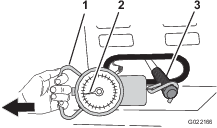
-
Using the spring scale, pull the clutch handle to the ON position as shown in Figure 65.
-
Observe the spring scale while pulling to see what the highest pressure is when moving the clutch handle from the OFF position to the ON position (Figure 65).
Note: Normal clutch pressure is 15 to 30 kg (35 to 55 lb).
-
If the clutch pressure is greater than or less than 15 to 30 kg (35 to 55 lb), contact an Authorized Toro Service Dealer.
-
Gearbox-Oil Specifications
Oil type: SAE 90 gear oil
Gearbox capacity: 2.13 L (72 fl oz)
Checking the Gearbox Oil
| Maintenance Service Interval | Maintenance Procedure |
|---|---|
| Every 40 hours |
|
Important: If the oil level in the gearbox is too low or too high and you run the engine, you may damage the engine or the gearbox. This type of damage is not covered by the warranty.
-
Park the machine on a level surface and shut off the engine.
-
Allow the engine to cool.
-
Disconnect the wire from the spark plug; refer to Disconnecting the Spark-Plug Wire.
-
Locate the gearbox between the engine and the front cowl.
-
At the right side of the gearbox, examine the oil level in the sight glass (Figure 66).
-
If the oil level is below the bottom 1/3 of the sight glass, add oil as follows:
-
Remove the fill plug from the fill port in the housing of the gearbox (Figure 66).
-
Slowly pour the specified oil into the fill port until the oil level is between 1/3 and 1/2 of the sight glass (Figure 66).
-
Clean the fill plug.
-
Apply PTFE thread-sealing tape to the threads of the plug.
-
Install the plug into the fill port in the housing (Figure 66).
-
Replacing the Gearbox Oil
| Maintenance Service Interval | Maintenance Procedure |
|---|---|
| Every 800 hours |
|
-
Park the machine on a level surface and shut off the engine.
-
Allow the engine to cool.
-
Disconnect the wire from the spark plug; refer to Disconnecting the Spark-Plug Wire.
-
Align a drain pan with a 2.8 L (3 US qt) capacity under the drain plug (Figure 66).
-
Remove the drain plug from the drain port and completely drain the gearbox oil (Figure 66).
-
Remove the fill plug (Figure 66).
-
Clean the drain and fill plugs and apply PTFE thread-sealing tape to the plug threads.
-
Install the drain plug in the drain port (Figure 66).
-
Slowly pour the specified oil into the fill port until the oil level is between 1/3 and 1/2 of the sight glass (Figure 66).
-
Install the fill plug in the fill port (Figure 66).
Belt Maintenance
Inspecting the Belts
| Maintenance Service Interval | Maintenance Procedure |
|---|---|
| After the first 25 hours |
|
| Every 40 hours |
|
-
Park the machine on a level surface and shut off the engine.
-
Allow the machine to cool.
-
Disconnect the wire from the spark plug; refer to Disconnecting the Spark-Plug Wire.
-
Remove the divider plate; refer to Removing the Divider Plate.
-
Move the clutch lever to the OFF position.
-
Examine the belts for wear or damage. If the belts are worn or damaged, replace them; refer to Replacing the Belts.
-
Examine the pulleys for wear, damage, and misalignment; refer to Aligning the Pulleys.
-
Install the divider plate; refer to Installing the Divider Plate.
Adjusting the Belt Tension
Clutch air gap: 2.5 to 6.5 mm (3/32 to 1/4 inch)
-
Park the machine on a level surface and shut off the engine.
-
Allow the machine to cool.
-
Disconnect the wire from the spark plug; refer to Disconnecting the Spark-Plug Wire.
-
Move the clutch lever to the ON position.
-
Measure the air gap between the engine deck and the roller on the clutch (Figure 67).
-
If the measured air gap is not within the specified range, adjust the gap as follows:
-
Move the clutch lever to the OFF position.
-
Loosen the nuts and bolts that secure the engine to the engine deck (Figure 68).
-
Move the engine position as follows:
-
Align a straightedge across the engine pulley and the idler pulley (Figure 69).
-
If necessary, pivot the engine on the engine deck until the engine pulley and idler pulley are aligned to the straightedge (Figure 69).
-
Tighten the nuts and bolts that secure the engine to the engine deck to a torque of 18 N∙m (13 ft-lb).
-
Check the air gap between the engine deck and the roller on the clutch. If the air gap is not within the specified range, repeat step 6 until the air gap measurement is within the specified range.
-
Install the divider plate; refer to Installing the Divider Plate.
-
Important: Ensure that the paddles do not rotate when the clutch lever is in the OFF position.
Replacing the Belts
| Maintenance Service Interval | Maintenance Procedure |
|---|---|
| Every 2 years |
|
Removing the Belts
-
Park the machine on a level surface and shut off the engine.
-
Allow the machine to cool.
-
Disconnect the wire from the spark plug; refer to Disconnecting the Spark-Plug Wire.
-
Move the clutch lever to the OFF position.
-
Remove the divider plate; refer to Removing the Divider Plate.
-
Remove the bolt that secures the belt guide to the engine, and remove the belt guide (Figure 70).
-
Slip the forward belt forward and off the idler pulley (Figure 71).
-
Slip the rear belt rearward and off the idler pulley (Figure 71).
-
Slip the belts off the engine pulley.
-
Remove the belts from the machine.
Installing the Belts
-
Park the machine on a level surface and shut off the engine.
-
Allow the machine to cool.
-
Disconnect the wire from the spark plug; refer to Disconnecting the Spark-Plug Wire.
-
Ensure that the clutch lever is in the OFF position.
-
Align the rear belt to the rear groove in the engine pulley.
Note: Do not align the rear belt to the idler pulley.
-
Align the forward belt to the forward groove of the idler pulley.
-
Slip the rear belt over the idler pulley and align the belt to the rear pulley groove.
-
Slip the forward belt over the engine pulley and align the belt to the forward pulley groove.
-
Check the belt tension; refer to step 4 through 6 in Adjusting the Belt Tension.
-
Loosely secure the belt guide to the engine (Figure 70) with the bolt that was removed in step 6 of Removing the Belts.
-
Adjust the belt guide; refer to Adjusting the Belt Guide.
-
Install the divider plate; refer to Installing the Divider Plate.
Adjusting the Belt Guide
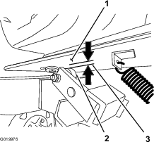
Note: To access the belt guide, remove the divider plate; refer to Removing the Divider Plate.
Guide air gap: 2.5 to 4.0 mm (3/32 to 5/32 inch)
-
Park the machine on a level surface and shut off the engine.
-
Allow the machine to cool.
-
Disconnect the wire from the spark plug; refer to Disconnecting the Spark-Plug Wire.
-
Ensure that the clutch lever is in the ON position.
-
Ensure that the belt tension is correct; refer to Adjusting the Belt Tension.
-
Check that the air gap between the belt guide and the belts is 2.5 to 4.0 mm (3/32 to 5/32 inch); refer to Figure 72.
-
If the air gap is not within the specified range, do the following:
-
Loosen the bolt that secures the belt guide to the engine (Figure 72).
Important: Ensure that the belt guide is toward the engine pulley.
-
Rotate the belt guide up or down until there is an air gap of 2.5 to 4.0 mm (3/32 to 5/32 inch) between the guide and each belt (Figure 72).
Important: The belt guide should not contact the belts with the clutch lever in the ON position.
Note: If the air gap between the belt guide and both belts cannot be attained, then 1 of the belts is too long.
-
Tighten the bolt that secures the belt guide to the engine (Figure 72).
-
Check the clutch operation; refer to Checking the Clutch Operation.
-
-
Install the divider plate; refer to Installing the Divider Plate.
Checking the Clutch Operation
| Maintenance Service Interval | Maintenance Procedure |
|---|---|
| Every 40 hours |
|
Important: The paddles must not rotate in an empty drum when the clutch lever is in the OFF position.
-
Move the clutch lever to the OFF position.
-
Start the engine.
-
If the paddles rotate with the clutch lever to the OFF position do the following:
-
Shut off the engine.
-
Check the air gap between the belt guide and the belts.
Note: If the air gap is larger than 4.0 mm (5/32 inch), decrease the gap between the belt guide and the belts; refer to Adjusting the Belt Guide.
-
-
Repeat steps 1 through 3 until all the following conditions are met:
-
The engine is run at 2/3 throttle.
-
The clutch lever is in the OFF position.
-
The paddles do not rotate in an empty drum while the engine is running.
-
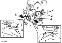
Aligning the Pulleys
-
Park the machine on a level surface and shut off the engine.
-
Allow the machine to cool.
-
Disconnect the wire from the spark plug; refer to Disconnecting the Spark-Plug Wire.
-
Remove the divider plate; refer to Removing the Divider Plate.
-
Place a straightedge across the face of the engine pulley and idler pulley (Figure 73).
Note: Both pulleys must be aligned flush with the straightedge.
-
If the pulleys are not aligned do the following:
-
Move the clutch lever to the OFF position.
-
Loosen the locknuts and setscrews that secure the idler pulley to the idler shaft (Figure 73).
-
Using a soft-face mallet, tap the idler pulley forward or backward along the idler shaft until the engine pulley and idler pulley are aligned to the straight edge (Figure 73).
-
Tighten the set screws and locknuts that secure the idler pulley to the idler shaft (Figure 73).
-
-
Install the divider plate; refer to Installing the Divider Plate.
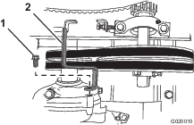
Paddle Maintenance
Adjusting the Paddle Blades
-
Park the machine on a level surface and shut off the engine.
-
Allow the engine to cool.
-
Disconnect the wire from the spark plug; refer to Disconnecting the Spark-Plug Wire.
-
Remove the nuts and bolts that secure the grate to the drum, and remove the grate (Figure 74, Figure 75, or Figure 76).
-
Loosen the carriage bolts and nuts that secure the wipers to the paddle bladess (Figure 77).
Note: If necessary, tip the drum to the dump position to access the paddles.
-
Adjust the rubber wipers to be close to the drum wall and position the metal paddle blades so that the outer edge is 3 to 6 mm (1/8 to 1/4 inch) from the outer edge of the wipers (Figure 77). Tighten the nuts and bolts to secure the blades to the paddles.
Note: Ensure that the clutch lever is in the OFF position and rotate the paddles as needed.
-
Install the grate with the nuts and bolts that you removed in step 4, and tighten the nuts and bolts until they are secure.
Cleaning
Cleaning the Machine
Regular cleaning and washing with mild detergent and water increases the life span of the machine. Clean the machine after each use before the dirt hardens.
Remove dirt and grime from the external parts of the entire machine, especially the engine. Clean dirt and concrete materials from the outside of the engine.
Ensure that the fuel cap and the oil-fill cap/dipstick are secure to avoid getting water in the engine.
Use care when using a high-pressure sprayer because it can damage the safety decals, instruction signs, and the engine.
Important: Lubricate the bearings and seals after cleaning; refer to Lubricating the Bearings and Seals.
Storage
For storage over 30 days, prepare the machine as follows:
-
Remove dirt and grime from the external parts of the entire machine, especially the engine. Clean dirt and debris from the outside of the engine cylinder-head fins and blower housing.
Important: You can wash the machine with mild detergent and water.
-
Condition the fuel system as follows:
-
Add a petroleum-based stabilizer/conditioner to fuel in the tank. Follow the mixing instructions from the stabilizer manufacturer. Do not use an alcohol-based stabilizer (ethanol or methanol).
Important: Do not store stabilizer/conditioned fuel over 90 days.
Note: Fuel stabilizer/conditioner is most effective when mixed with fresh fuel and used at all times.
-
Run the engine for 5 minutes to distribute the conditioned fuel through the fuel system.
-
Shut off the engine, allow it to cool, and drain the fuel tank using a pump-type siphon. Dispose of fuel properly; recycle it according to local codes.
-
Start the engine and run it until it stops.
-
Choke the engine.
-
Start and run the engine until it does not start again.
-
-
Clean the sediment cup; refer to Cleaning the Fuel-Sediment Cup.
-
Service the air cleaner; refer to Servicing the Air Cleaner.
-
Change the engine oil; refer to Changing the Engine Oil.
-
Remove the spark plug and check the condition; refer to Servicing the Spark Plug.
-
Condition the engine as follows:
-
Pour 2 tablespoons of engine oil into the spark-plug hole; refer to Removing the Spark Plug.
-
Pull the recoil-start handle slowly to crank the engine and distribute the oil inside the cylinder.
-
Install the spark plug; refer to Installing the Spark Plug.
Note: Do not install the wire on the spark plug.
-
-
Grease the machine; refer to Lubricating the Bearings and Seals.
-
Check and tighten all bolts, nuts, and screws. Repair or replace any part that is damaged.
-
Paint all scratched or bare metal surfaces with paint available from your Authorized Service Dealer.
-
Store the machine in a clean, dry garage or storage area.
-
Cover the machine to protect it and keep it clean.
Troubleshooting
| Problem | Possible Cause | Corrective Action |
|---|---|---|
| The engine does not start. |
|
|
| The engine lacks power or runs rough. |
|
|
| The belts slip or come off the pulleys (belt-drive models only). |
|
|
| The paddles rotate when the clutch lever is in the Off position (belt-drive models only). |
|
|
| The paddles rotate when the clutch lever is in the Off position (gearbox model only). |
|
|
| The paddles do not rotate when the clutch lever is in the On position (belt-drive models only). |
|
|
| The paddles do not rotate when the clutch lever is in the On position (gearbox model only). |
|
|
| The paddles rotate slowly when the clutch lever is in the On position (belt-drive models only). |
|
|
| The paddles rotate slowly when the clutch lever is in the On position (gearbox model only). |
|
|