


Maintenance
Warning
Failure to properly maintain the machine could result in premature failure of machine systems causing possible harm to you or bystanders.
Keep the machine well maintained and in good working order as indicated in these instructions.
Note: Determine the left and right sides of the machine from the normal operating position.
Important: Do not tip the machine at an angle greater than 25°. Tipping the machine beyond 25° leads to oil leaking into the combustion chamber and/or fuel leaking out of the fuel-tank cap.
Important: Refer to your engine Owner’s Manual for additional maintenance procedures.
Recommended Maintenance Schedule(s)
| Maintenance Service Interval | Maintenance Procedure |
|---|---|
| After the first 20 operating hours |
|
| Before each use or daily |
|
| Every 25 hours |
|
| Every 50 hours |
|
| Every 100 hours |
|
| Every 1,000 hours |
|
Pre-Maintenance Procedures
Pre-Maintenance Safety
-
Disengage the drives and the cutting unit, engage the parking brake, shut off the engine, and disconnect the spark-plug wire. Wait for all movement to stop before adjusting, cleaning, or repairing the machine.
-
If the engine must be running to perform a maintenance adjustment, keep your hands, feet, clothing, and any parts of the body away from the cutting unit, attachments, and any moving parts. Keep bystanders away.
-
Keep all parts in good working condition and all hydraulic fittings tight. Replace all worn, damaged, or missing parts and decals. Keep all fasteners tight to ensure that the machine is in safe working condition.
-
Check the grass catcher components frequently and replace them when necessary.
-
Clean grass and debris from the cutting unit, drives, mufflers, cooling screens, and the engine to help prevent fires. Clean up oil or fuel spills.
-
Carefully release pressure from components with stored energy.
-
Replace faulty silencers.
-
If major repairs are ever needed or if assistance is desired, contact an authorized Toro distributor.
-
To ensure optimum performance and continued safety certification of the machine, use only genuine Toro replacement parts and accessories. Replacement parts and accessories made by other manufacturers could be dangerous, and such use could void the product warranty.
Lubrication
Greasing the Machine
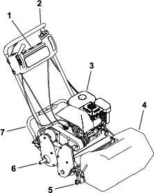
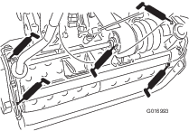
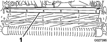
Lubricate the 12 grease fittings on the mower using No. 2 lithium grease. For best results, use a hand-operated grease gun.
The grease fitting locations are as follows:
-
2 on the front roller (Figure 24)
-
2 on the reel bearings (Figure 24)
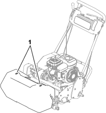
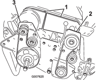
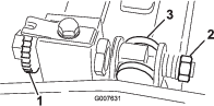
-
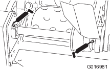
2 on the drum axles (Figure 25)
-
3 on the differential (Figure 25)
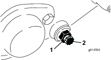
-
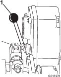
2 on the reel countershaft bearings (Figure 26)
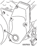
-
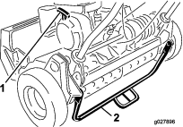
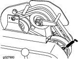
1 on the belt idler pivots (Figure 27).
-
Wipe each grease fitting with a clean rag.
-
Pump grease into each fitting.
Important: Do not apply too much pressure or the grease seals may become permanently damaged.
-
Wipe off any excess grease.
Engine Maintenance
Engine Safety
-
Fuel is flammable and explosive, and can cause personal injury.
-
Check all fuel lines for tightness and wear regularly. Tighten or repair them as needed.
-
Tipping the machine may cause the fuel to leak. Do not tip the machine at an angle greater than 25°. If fuel comes in contact with the fuel cap, replace the cap.
-
Run the engine dry or remove the fuel with a hand pump; never siphon the fuel. If you must drain the fuel tank, do it outdoors.
Servicing the Engine Oil
Fill the crankcase with approximately 0.6 L (20 fl oz) of the proper viscosity oil before starting. The engine uses a high-quality oil that has the American Petroleum Institute (API) service classification of SE or higher. Select the proper oil viscosity (weight) based on the ambient temperature. Figure 28 illustrates the temperature/viscosity recommendations.
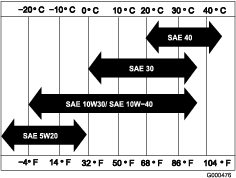
Note: Multi-grade oils (5W-20, 10W-30 and 10W-40) increase oil consumption. Check the engine-oil level more frequently when you use these oils.
Checking the Engine-Oil Level
-
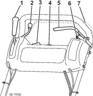
Park the machine on a level surface and clean the area around the oil-level gauge (Figure 29).
-
Remove the oil-level gauge by rotating it counterclockwise.
-
Wipe the oil-level gauge clean and insert it into the filler port, but do not screw the gauge into the port.
-
Remove the oil-level gauge and check the level of the oil.
-
If the level is low, add only enough oil to raise the level until it is between the hatch marks on the gauge (Figure 30).
Important: Do not overfill the crankcase.
-
Install the oil-level gauge and wipe up any spilled oil.
Changing the Engine Oil
-
Start and run the engine for a few minutes to warm the engine oil.
-
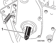
At the rear of the machine, place a drain pan under the drain plug (Figure 29). Loosen the drain plug.
-
Push down on the handle to tip the machine and engine backward, allowing all the oil to run into the drain pan.
Important: Do not tip the machine at an angle greater than 25°. Tipping the machine beyond 25° leads to oil leaking into the combustion chamber and/or fuel leaking out of the fuel-tank cap.
-
Install the drain plug and refill the crankcase with the specified oil.
-
Torque the drain plug to 20 to 23 N∙m (15 to 17 ft-lbs).
-
Wipe up any spilled oil.
-
Dispose of the used oil properly. Recycle as per local codes.
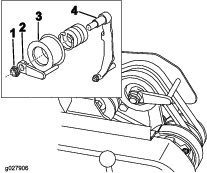
Servicing the Air Cleaner
Important: Service the air cleaner more often in dirty or dusty conditions
-
Ensure that the spark-plug wire is removed from the spark plug.
-
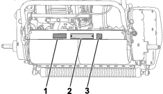
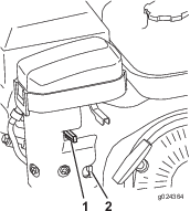
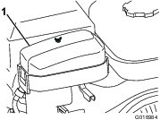
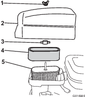
Remove the wing nut that secures the air-cleaner cover, and remove the cover (Figure 31).
-
Clean the cover.
-
If the foam element is dirty, remove it from the paper element (Figure 32) and clean it as follows:
-
Wash the foam element in a solution of liquid soap and warm water. Squeeze it to remove dirt, but do not twist it, as the foam may tear.
-
Dry the foam element by wrapping it in a clean rag. Squeeze the rag and foam element to dry it, but do not twist it, as the foam may tear.
-
Saturate the foam element with clean engine oil. Squeeze the element to remove excess oil and to distribute the oil.
Note: A foam element that is damp with oil is desirable.
-
-
Check the condition of the paper element. Clean it by gently tapping or replace it as necessary.
Important: Do not use compressed air to clean the paper element.
-
Install the foam element, paper element, and air-cleaner cover.
Important: Do not operate the engine without the air-cleaner element, as extreme engine wear and damage can result.
Servicing the Spark Plug
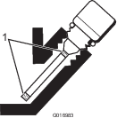
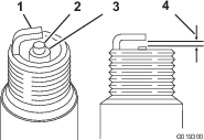
Use an NGK BR6HS spark plug or equivalent. The correct air gap is 0.6 to 0.7 mm (0.024 to 0.028 inch).
-
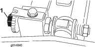
Pull the molded wire off the spark plug (Figure 33).
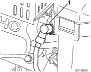
-
Clean around the spark plug and remove the plug from the cylinder head.
Important: Replace a cracked, fouled, or dirty spark plug. Do not sand blast, scrape, or clean the electrodes because engine damage could result from grit entering the cylinder.
-
Set the air gap at 0.6 to 0.7 mm (0.024 to 0.028 inch) as shown in Figure 34. Install the correctly gapped spark plug and tighten it firmly to 23 N∙m (17ft-lb).
Fuel System Maintenance
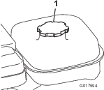
Cleaning the Fuel-Tank Screen
-
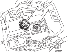
Unscrew and remove the fuel-tank cap from the fuel tank (Figure 35).
-
Remove the fuel-tank screen from inside the fuel tank.
-
Clean the screen in clean fuel and install it in the tank.
-
Install the fuel-tank cap to the fuel tank.
Electrical System Maintenance
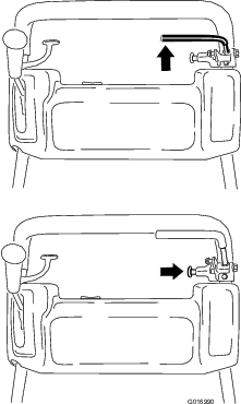
Servicing the Traction-Interlock Switch
Use the following procedure if the traction-interlock switch needs adjustment or replacement.
-
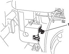
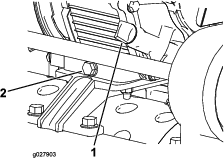
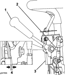
Ensure that the engine is off and the traction lever is disengaged and resting against the neutral stop (Figure 36).
-
Loosen the interlock switch mounting fasteners (Figure 36).
-
Place a 0.8 mm (0.032 inch) thick shim between the traction lever and the interlock switch (Figure 36).
-
Tighten the interlock switch mounting fasteners and check the gap again.
Note: The traction lever must not contact the switch.
-
Engage the traction lever and verify that the switch loses continuity.
Note: Replace the switch if necessary.
Brake Maintenance
Adjusting the Service/Parking Brake
If the service/parking brake slips during operation, adjust it.
-
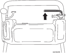
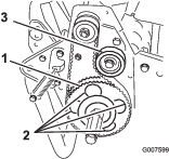
Engage the service brake, push in the parking brake knob, and allow the service brake to rest on the parking-brake pin (Figure 37).
-
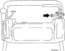
Using a spring scale, press rearward on the service-brake lever (Figure 38). The parking brake should release when a force of 13.5 to 18 kg (30 to 40 lb) is attained. If the parking brake releases before 13.5 to 18 kg (30 to 40 lb) of force is attained, adjust the brake cable.
-
Loosen the retainer that secures the V-belt cover and pivot the cover open (Figure 39).
-
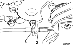
To adjust the brake cable tension, proceed as follows.
-
To decrease the cable tension, loosen the front cable jam nut and tighten the rear jam nut (Figure 40). Repeat steps 1 and 2 and adjust the tension if necessary.
-
To increase the cable tension, tighten the front cable jam nut and loosen the rear jam nut (Figure 40). Repeat steps 1 and 2 and adjust the tension if necessary.
Note: You can adjust the cable at the jam nut brackets by the control panel or at the bracket at the base of the engine.
-
-
Close the cover and secure the retainer.
Belt Maintenance
Adjusting the Belts
Ensure that the belts are properly tensioned to ensure proper operation of the machine and prevent unnecessary wear. Check the belts frequently.
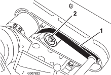
Adjusting the Reel-Drive Belt
-
Remove the belt-cover mounting fasteners and the belt cover to expose the belt (Figure 41).
-
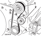
Check the tension by pressing the belt at mid-span of the pulleys (Figure 42) with 18 to 22 N (4 to 5 lb) of force. The belt should deflect 6 mm (1/4 inch).
-
Complete the following steps to adjust the belt tension:
-
Loosen the idler-pulley mounting nut and pivot the idler pulley clockwise against the backside of the belt until you attain the desired belt tension (Figure 42).
Important: Do not over-tension the belt.
-
Tighten the nut to lock the adjustment.
-
-
Install the belt cover by placing it in position.
-
While maintaining a slight gap between the cover seal and the side plate, install each mounting bolt until the threads engage in the insert.
Note: The gap allows visual alignment of the bolts to the threaded inserts.
-
After all bolts are installed, tighten them until the stand-offs inside the cover contact the side plate.
Note: Do not overtighten the bolts.
Adjusting the Traction-Drive Belt
-
Remove the belt-cover mounting fasteners and the belt cover to expose the belt (Figure 43).
-
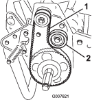
Check the tension by pressing the belt at mid span of the pulleys (Figure 44) with 18 to 22 N (4 to 5 lb) of force.
Note: The belt should deflect 6 mm (1/4 inch).
-
Complete the following to adjust the belt tension:
-
Loosen the idler-pulley mounting nut and pivot the idler pulley clockwise against the backside of the belt until the desired belt tension is attained (Figure 44).
Important: Do not over-tension the belt.
-
Tighten the nut to lock the adjustment.
-
-
Install the belt cover by placing it in position.
-
While maintaining a slight gap between the cover seal and the side plate, install each mounting bolt until the threads engage in the insert.
Note: The gap allows visual alignment of the bolts to the threaded inserts.
-
After all bolts are installed, tighten them until the stand-offs inside the cover contact the side plate.
Note: Do not overtighten the bolts.
Adjusting the Differential Belt
-
Remove the bolts securing the front and rear sections of the differential cover to the differential housing and slide the cover sections away to expose the belt.
-
Check the tension by pressing the belt at mid span of the pulleys (Figure 45) with 22 to 26 N (5 to 6 lb) of force.
Note: The belt should deflect 6 mm (1/4 inch).
-
Complete the following to adjust the belt tension:
-
Loosen the idler pulley mounting nut and pivot the idler pulley clockwise against the backside of the belt until the desired belt tension is attained (Figure 45).
Important: Do not over-tension the belt.
-
Tighten the nut to lock the adjustment.
-
-
Install the belt cover by placing it in position.
-
While maintaining a slight gap between the cover seal and the side plate, install each mounting bolt until the threads engage in the insert. The gap allows visual alignment of the bolts to the threaded inserts.
-
After all bolts are installed, tighten them until the stand-offs inside the cover contact the side plate. Do not overtighten the bolts.
Adjusting the Primary V-Belts
-
To adjust the belt tension on primary V-belts, first check the adjustment of the traction control; refer to Adjusting the Traction Control. If you are unable to attain the 27 to 32 N (6 to 7 lb) force required in adjusting the traction control, proceed to the next step.
-
Loosen the retainer that secures the V-belt cover and pivot the cover open (Figure 46).
-
To increase the belt tension, loosen the engine mounting bolts and move the engine backwards in the slots.
Important: Do not over-tension the belt.
-
Tighten the mounting bolts.
Note: The distance between the center of the drive pulley and the center of the driven pulley should be approximately 12.9 cm (5.1 inches) after the new V-belts are installed.
-
After tensioning the primary V-belts, check the alignment of the engine output-shaft pulley and the counter-shaft pulley with a straightedge.
-
If the pulleys are misaligned, loosen the screws that secure the engine mounting base to the machine frame and slide the engine from side to side until the pulleys are aligned within 0.7 mm (0.030 inch).
-
Tighten the mounting screws and check the alignment.
-
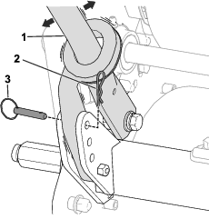
To push or pull the machine easier without starting the engine, adjust the belt guide (Figure 47, inset) as follows:
-
Engage the clutch.
-
Loosen the locknut that secures the idler pulley and the belt guide to the idler arm.
-
Rotate the belt guide clockwise until a gap of approximately 1.5 mm (0.06 inch) is obtained between the guide finger and the backside of the drive belts.
-
Tighten the locknut that secures the idler pulley and the belt guide to the idler arm.
-
-
Close the cover and secure the retainer.
Replacing the Differential Belt
-
Remove the bolts that secure the traction drive and reel-drive belt covers to the right side plate and remove the belt covers.
-
Loosen the idler pulley mounting nut on each idler pulley and pivot each idler pulley counterclockwise away from the backside of each belt to release the belt tension.
-
Remove the belts.
-
Remove the bolts that secure the front and rear sections of the differential cover to the differential housing and slide the cover sections away to expose the belt (Figure 48).
-
Loosen the idler pulley mounting nut on the differential idler pulley and pivot the idler pulley counterclockwise away from the backside of the belt to release the belt tension.
-
Remove the 2 bolts and 2 locknuts that secure the front clutch housing to the side plate (Figure 48).
-
Rotate the housing 180° so that the bottom of the housing points upward.
-
Remove the 2 bolts and 2 locknuts that secure the right rear bearing housing to the side plate (Figure 48).
-
Rotate the housing 180° so that the bottom of the housing points upward.
-
Remove the old belt.
-
Slide the new belt over the rotated housing covers, the differential cover sections, and onto the differential pulleys.
-
Ensure that the idler pulley is positioned against the backside of the belt.
-
Rotate both housings back into the upright position and secure them to the side plate with the bolts and nuts that you previously removed.
-
Adjust the differential belt tension; refer to Adjusting the Differential Belt.
-
Adjust the belt tension on the traction drive and reel-drive belts; refer to Adjusting the Traction-Drive Belt, and Adjusting the Reel-Drive Belt.
-
Install the differential, traction drive, and reel-drive covers.
Controls System Maintenance
Adjusting the Traction Control
If the traction control does not engage or it slips during operation, an adjustment is necessary.
-
Move the traction control to the DISENGAGED position.
-
Loosen the retainer that secures the V-belt cover and pivot the cover open (Figure 46).
-
To increase the cable tension, loosen the front-cable jam nut and tighten the back-cable jam nut (Figure 49) until a force of 8 to 9 Nm (6 to 7 lb) is created to engage the traction control.
Note: Measure the force at the control knob.
-
Tighten the front-cable jam nut.
-
Close the cover and secure the retainer.
-
Check the traction-control operation.
Blade Safety
Use care when checking the cutting-unit reel. Wear gloves and use caution when servicing the reel.
Leveling the Rear Drum to the Reel
-
Park the machine on a flat, level surface, preferably a precision steel work plate.
-
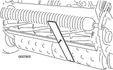
Place a 0.6 x 2.5 cm (1/4 x 1 inch) flat steel strip, approximately 73.6 cm (29 inches) long, under the reel blades and against the front edge of the bedknife to prevent the bedbar from resting on the work surface.
-
Raise the front roller so that only the rear drum and the reel are on the surface.
-
Firmly press down on the machine above the reel so that all reel blades contact the steel strip.
-
While pressing down on the reel, slide a feeler gauge under one end of the drum, then check the other end of the drum.
Note: If there is a gap between the drum and the work surface, greater than 0.25 mm (0.010 inch), on either end, adjust the drum (proceed to step 6). If the gap is less than 0.25 mm (0.010 inch), no adjustment is required.
-
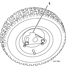
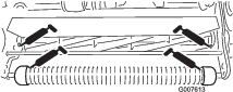
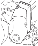
Remove the rear belt cover from the right side of the machine (Figure 50).
-
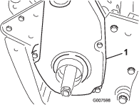
Rotate the driven pulley until the holes align with the 4 roller bearing flange screws (Figure 51).
-
Loosen the 4 roller bearing screws and the screw that secures the idler pulley.
-
Raise or lower the right side of the roller assembly until the gap is less than 0.25 mm (0.010 inch).
-
Tighten the roller bearing screws.
-
Adjust the belt tension and tighten the idler pulley mounting screw (Figure 51).
Adjusting the Bedknife to the Reel
Adjust the bedknife to the reel after grinding, backlapping, or disassembling the cutting unit. This procedure is not intended as a daily adjustment.
-
Park the machine on a flat, level work surface.
-
Tilt the machine back on the handle to expose the bedknife and the reel.
Important: Do not tip the machine at an angle greater than 25°. Tipping the machine beyond 25° leads to oil leaking into the combustion chamber and/or fuel leaking out of the fuel-tank cap.
-
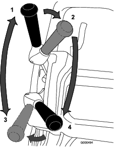
Rotate the reel so that a blade crosses the bedknife edge between the first and second bedknife screw heads on the right side of the cutting unit (Figure 52).
-
Rotate the reel so that a blade crosses the bedknife edge between the first and second bedknife screw heads on the right side of the cutting unit.
-
Insert the 0.05 mm (0.002 inch) shim between the marked blade and the bedknife edge at the point where the marked blade crosses the bedknife edge.
-
Turn the right bedbar-adjusting screw until you feel light pressure (i.e., drag) on the shim by sliding it side-to-side (Figure 52).
-
Remove the shim.
-
For the left side of the cutting unit, slowly rotate the reel so that the closest blade crosses the bedknife edge between the first and second screw heads.
-
Repeat steps 4 through 7 for the left side of the cutting unit and left bedbar-adjusting screw.
-
Repeat steps 5 through 7 until light drag is achieved on both the right and left sides of the cutting unit utilizing the same contact points.
-
To obtain light contact between the reel and bedknife, turn each bedbar-adjusting screw clockwise 3 clicks.
Note: Each click turned on the bedbar-adjusting screw moves the bedknife 0.018 mm (0.0007 inch). Clockwise rotation moves the bedknife edge closer to the reel and counterclockwise rotation move the bedknife edge away from the reel.
-
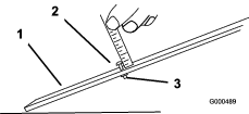
Test the cutting performance by inserting a long strip of cutting performance paper between the reel and bedknife, perpendicular to the bedknife (Figure 53). Slowly rotate the reel forward; it should cut the paper.
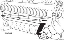
Note: If you see excessive contact/reel drag, it will be necessary to backlap, face the front of the bedknife, or grind the cutting unit to achieve the sharp edges that are necessary for precise cutting.
Adjusting the Height-of-Cut
-
Verify that the rear roller is level and that the bedknife-to-reel contact is correct. Tip the machine back on the handle to expose the front and rear rollers and the bedknife.
Important: Do not tip the machine at an angle greater than 25°. Tipping the machine beyond 25 ° leads to oil leaking into the combustion chamber and/or fuel leaking out of the fuel-tank cap.
-
Loosen the locknuts that secure the height-of-cut arms to the height-of-cut brackets (Figure 54).
-
Loosen the nut on the gauge bar (Figure 55) and set the adjusting screw to the desired height-of-cut. The distance between the bottom of the screw head and the face of the bar is the height of cut.
-
Hook the screw head on the cutting edge of the bedknife and rest the rear end of the bar on the rear roller (Figure 56).
-
Rotate the adjusting screw until the roller contacts the front of the gauge bar.
-
Adjust both ends of the roller until the entire roller is parallel to the bedknife.
Important: When set properly, the rear and front rollers contact the gauge bar and the screw is snug against the bedknife. This ensures that the height-of-cut is identical at both ends of the bedknife.
-
Tighten the nuts to lock the adjustment.
Important: To avoid scalping on undulating turf, ensure that the roller supports are positioned rearward (the roller closer to the reel).
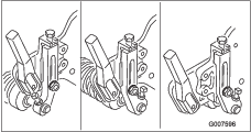
Note: The front roller can be put in 3 different positions (Figure 57), depending on the application and needs of the user.
-
Use the front position when a groomer is installed.
-
Use the middle position without a groomer.
-
Use the third position in extremely undulating turf conditions.
-
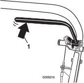
Adjusting the Grass Shield Height
Adjust the shield to ensure proper grass clipping discharge into the basket.
-
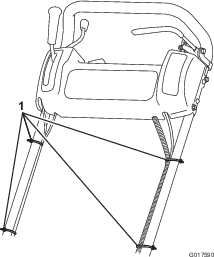
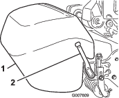
Measure the distance from the top of the front support rod to the front lip of the shield at each end of the cutting unit (Figure 58).
-
The height of the shield from the support rod for normal cutting conditions should be 10 cm (4 inches). Loosen the bolts and nuts that secure each end of the shield to the side plate and adjust the shield to the correct height.
-
Tighten the fasteners.
Note: You can lower the shield for dry turf conditions (clippings fly over the top of the basket) or raise it to allow for heavy, wet grass conditions (clippings build up on the rear of the basket).
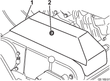
Adjusting the Cut-Off Bar
Adjust the cut-off bar to ensure that the clippings are cleanly discharged from the reel area.
-
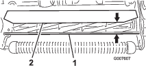
Loosen the screws that secure the top bar (Figure 59) to the cutting unit.
-
Insert a 1.5 mm (0.060 inch) feeler gauge between the top of the reel and the bar and tighten the screws.
-
Ensure that the bar and reel are equal distances apart across the entire reel.
Note: The bar is adjustable to compensate for changes in turf conditions. Adjust the bar closer to the reel when the turf is extremely wet. By contrast, adjust the bar further away from the reel when turf conditions are dry. The bar should be parallel to the reel to ensure optimum performance. Adjust the bar when you adjust the shield height or when you sharpen the reel on a reel grinder.
Identifying the Bedbar
To determine if the bedbar is standard or aggressive, check the left bedbar mounting ears. If the mounting ears are rounded, it is a standard bedbar. If the mounting ears have a notch in them, it is an aggressive bedbar (Figure 60).

Servicing the Bedbar
Removing the Bedbar
-
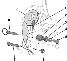
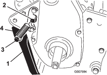
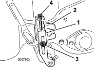
Turn the bedbar-adjuster screw counterclockwise to back the bedknife away from the reel (Figure 61).
-
Back out the spring-tension nut until the washer is no longer tensioned against the bedbar (Figure 61).
-
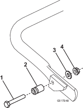
On each side of the machine, loosen the jam nut that secures the bedbar bolt (Figure 62).
-
Remove each bedbar bolt allowing the bedbar to be pulled downward and removed from the machine. Save the 2 nylon and 2 stamped steel washers on each end of the bedbar (Figure 62).
Installing the Bedbar
-
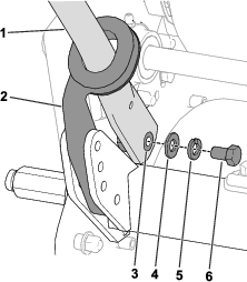
Install the bedbar, positioning the mounting ears between the washer and the bedbar adjuster.
-
Secure the bedbar to each side plate with the bedbar bolts (jam nuts on the bolts) and 8 washers.
Note: Position a nylon washer on each side of the side plate boss. Place a steel washer outside each of the nylon washers.
-
Torque the bolts to 27 to 36 N∙m (20 to 27 ft-lb).
-
Tighten the jam nuts until the outside thrust washers just rotate freely.
-
Tighten the spring-tension nut until the spring is collapsed, then back it off 1/2 turn.
-
Adjust the bedbar; refer to Adjusting the Bedknife to the Reel.
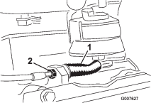
Backlapping the Reel
-
Remove the plug in the right reel-drive cover (Figure 63).
-
Insert a 1/2 inch-drive extension bar, connected to the backlapping machine, into the square hole in the center of the reel pulley.
-
Backlap according to the procedure in the Toro Sharpening Reel and Rotary Mowers Manual, Form 80-300 PT.
Danger
Contact with the reel or other moving parts can result in personal injury.
-
Stay away from the reel while backlapping.
-
Do not use a short-handled paint brush for backlapping. Part No. 29-9100 Handle assembly, complete or as individual parts, are available from your local authorized Toro distributor.
Note: For a better cutting edge, run a file across the front face of the bedknife when the lapping operation is completed. This removes any burrs or rough edges that may have built up on the cutting edge.
-
-
Install the plug in the cover when you complete this procedure.