Introduction
Important: To maximize the safety, performance, and proper operation of this machine, carefully read and fully understand the contents of this Operator’s Manual. Failing to follow these operating instructions or to receive proper training may result in injury. For more information on safe operating practices, including safety tips and training materials, go to www.Toro.com.
You may contact Toro directly at www.Toro.com for product and accessory information, help finding a dealer, or to register your product.
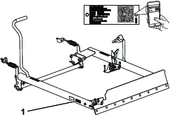
Whenever you need service, genuine Toro parts, or additional information, contact an Authorized Service Dealer or Toro Customer Service and have the model and serial numbers of your product ready. Figure 1 identifies the location of the model and serial numbers on the product. Write the numbers in the space provided.
Important: With your mobile device, you can scan the QR code on the serial number (if equipped) to access warranty, parts, and other product information.
This manual identifies potential hazards and has safety messages identified by the safety alert symbol (Figure 2), which signals a hazard that may cause serious injury or death if you do not follow the recommended precautions.

This manual uses 2 words to highlight information. Important calls attention to special mechanical information and Note emphasizes general information worthy of special attention.
Safety
Safety and Instructional Decals
 |
Safety decals and instructions are easily visible to the operator and are located near any area of potential danger. Replace any decal that is damaged or missing. |

Setup
Note: Determine the left and right sides of the machine from the normal operating position.
Preparing the Machine
-
Park the machine on a level surface.
-
Engage the parking brake.
-
Shut off the engine and remove the key.
Installing the Locking Pedal
Parts needed for this procedure:
| Pivot bracket | 1 |
| Carriage bolt (5/16 x 3/4 inch) | 2 |
| Locknut (5/16 inch) | 5 |
| Locking pedal | 1 |
| Bushing plate | 1 |
| Hex-head bolt (5/16 x 3/4 inch) | 3 |
| Spacer (5/8 x 1-1/16 inches) | 1 |
| Torsion spring | 1 |
| Washer (1-1/8 x 2 inches) | 1 |
| Retaining ring | 1 |
| Washer (5/8 x 1 inch) | 1 |
| Locknut (5/8 inch) | 1 |
| Locknut (1/4 inch) | 2 |
| Hub assembly | 1 |
| Bolt (1/4 x 2-3/4 inch) | 1 |
| Washer (9/32 inch) | 1 |
Installing the Pivot Bracket and the Locking Pedal on a Machine with Holes that Align with the Bushing Plate and the Pivot Bracket
-
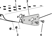
Assemble the pivot bracket onto the footrest with 2 carriage bolts (5/16 x 3/4 inch) and 2 locknuts (5/16 inch) as shown in Figure 5.
-
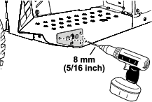
Using the pivot bracket as a drilling template, drill 3 holes (8 mm or 5/16 inch) into the flange of the footrest (Figure 6).
-
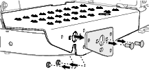
Remove the pivot bracket, 2 carriage bolts (5/16 x 3/4 inch), and 2 locknuts (5/16 inch) from the machine (Figure 7).
-
Remove any burrs from the 3 holes that you drilled in step 2.
-
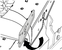
At the inboard side of the footrest flange, align the 3 holes in the pivot bracket to the 3 holes in the flange (Figure 8).
-
Assemble the pivot bracket to the footrest (Figure 9) with 3 hex-head bolts (5/16 x 3/4 inch) and 3 locknuts (5/16 inch).
-
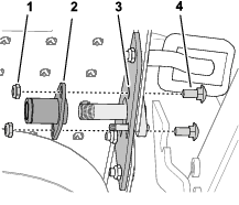
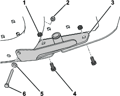
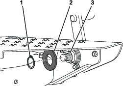
Assemble the spacer (5/8 x 1-1/16 inches) over the pivot shaft of the locking pedal (Figure 10).
-
Align the locking pedal to the left footrest and the holes in the pivot bracket (Figure 11).
-
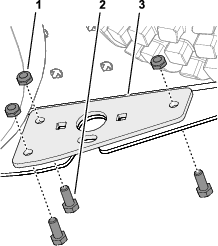
Assemble the bushing plate onto the pivot bracket and the footrest flange (Figure 12) with the 2 carriage bolts (5/16 x 3/4 inch) and 2 locknuts (5/16 inch).
-
Torque the locknuts to 71 to 92 N∙cm (100 to 130 in-lb)
-
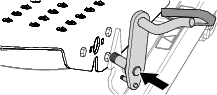
Slide the torsion spring onto the bushing plate while hooking 1 end of the spring onto the small stud on the locking pedal and pressing the other end against the floor plate (Figure 13).
Note: Position the spring onto the bushing plate as shown.
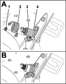
-
Secure the torsion spring to the small stud with a locknut (1/4 inch); refer to Figure 13.
-
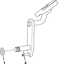
Secure the torsion spring to the bushing plate with a flat washer (1-1/8 x 2 inch) and a retaining ring (Figure 14).
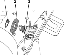
-
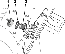
Secure the locking pedal to the footrest and the bushing plate with a flat washer (5/8 x 1 inch) and a locknut (5/8 inch); refer to Figure 15.
Note: Do not overtighten the nut; the locking pedal must pivot freely when pressed.
Installing the Hub Assembly and the Locking Pedal on a Machine with Holes that Align with the Hub Assembly
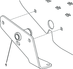
-
Install the hub assembly to the left footrest with 2 bolts (5/16 x 3/4 inch) and 2 locknuts (5/16 inch).
-
Secure the bottom of the hub assembly to the machine frame with a bolt (1/4 x 2-3/4 inch), a washer (1/4 inch), and a locknut (1/4 inch); refer to Figure 17.
-
Torque the locknuts to 71 to 92 N∙cm (100 to 130 in-lb)
-
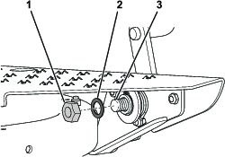
Align the locking pedal to the left footrest and the holes in the hub assembly (Figure 18).
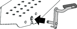
-
Insert the pivot shaft of the locking pedal through the hole in the left footrest and through the hub assembly (Figure 18).
-
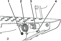
Slide the torsion spring onto the hub assembly while hooking 1 end of the spring onto the small stud on the locking pedal and pressing the other end against the floor plate (Figure 19).
Note: Position the spring onto the hub assembly as shown in Figure 19.
-
Secure the torsion spring to the small stud with a locknut (1/4 inch); refer to Figure 19.
-
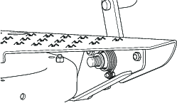
Secure the torsion spring to the bushing plate with a flat washer (1-1/8 x 2 inch) and a retaining ring (Figure 20).
-
Secure the locking pedal to the footrest and the hub assembly with a flat washer (5/8 x 1 inch) and locknut (5/8 inch); refer to Figure 21.
Note: Do not overtighten the nut; the locking pedal must pivot freely when pressed.
Discard the parts that were not necessary for your machine.
Installing the Mounting Brackets
Parts needed for this procedure:
| Mounting bracket assembly | 2 |
| Bolt (1/2 x 3-1/2 inches) | 4 |
| Locknut (1/2 inch) | 4 |
Note: Make sure that the front and rear tires are inflated to 28 to 41 kPa (4 to 6 psi).
-
Block up the rear of the machine and remove the rear tires.
Note: Position the blocks under the rear wheel motor mounts.
-
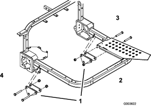
Loosely secure a mounting bracket assembly to the right and left foot rest tubes with 2 bolts (1/2 x 3-1/2 inches) and locknuts (1/2 inch). Position the mounting bracket assemblies and bolts as shown in Figure 22.
Note: The right mounting bracket does not need to be installed if the machine is equipped with a midmount tool bar.
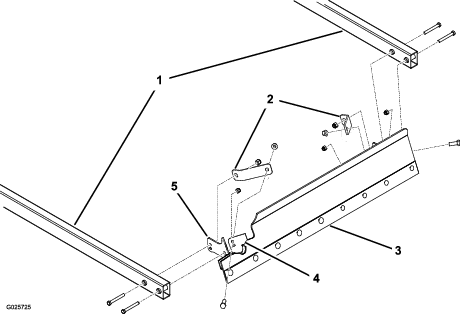
Installing the Lift Arms
Parts needed for this procedure:
| Right lift arm | 1 |
| Left lift arm | 1 |
| Clevis pin | 2 |
| Hairpin cotter pin | 2 |
| Torsion tube | 1 |
| Bolt (3/8 x 1 inch) | 4 |
| Locknut (3/8 inch) | 4 |
-
Position the lift arms so that the mounting hole of each lift arm bracket aligns with the holes in the mounting brackets (Figure 23).
-
Secure the right lift arm to the mounting bracket with a clevis pin and hairpin cotter pin (Figure 23).
-
Loosely install one end of the torsion tube to the right lift arm with 2 bolts (3/8 x 1 inch) and locknuts (3/8 inch); refer to Figure 23.
Note: Do not tighten the fasteners at this time.
-
Secure the left lift arm to the mounting bracket with a clevis pin and hairpin cotter pin (Figure 23).
-
Loosely install the other end of the torsion tube to the left lift arm with 2 bolts (3/8 x 1 inch) and locknuts (3/8 inch); refer to Figure 23.
Note: Do not tighten the fasteners at this time.
Installing the Blade
Parts needed for this procedure:
| 40-inch blade (optionally, you can purchase and install the 60-inch blade) | 1 |
| Brace plate | 2 |
| Bolt (3/8 x 1 inch) | 2 |
| Locknut (3/8 inch) | 6 |
| Bolt (3/8 x 3 inches) | 4 |
Note: Optionally, you can purchase a 60-inch blade. Install it as directed for the 40-inch blade in this section.
-
Loosely secure a brace plate to each of the inner mounting tabs on the blade assembly.
Note: Position the brace plates as shown in Figure 24.
-
Loosely secure the front of the lift arms to the blade mounting brackets and brace plates with 4 bolts (3/8 x 3 inch) and 4 locknuts (3/8 inch); refer to Figure 24.
Note: Using the upper mounting holes on the blade mounting brackets will make the blade operate more aggressively (Figure 24).
-
With the blade resting on the level surface, tighten the fasteners securing the lift arms to the blade (Figure 24).
Note: Torque the fasteners to 19 to 24 N∙m (14 to 18 ft-lb).
-
Tighten the bolts and locknuts securing the ends of the torsion tubes to the lift arms (Figure 23).
Note: Torque the fasteners to 19 to 24 N∙m (14 to 18 ft-lb).
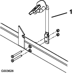
Installing the Lift-Arm Foot Pedal
Parts needed for this procedure:
| Lift-arm foot pedal | 1 |
| Bolt (3/8 x 3 inches) | 2 |
| Locknut (3/8 inch) | 4 |
| Spring bracket | 2 |
| Bolt (3/8 x 2-3/4 inches) | 2 |
| Extension spring | 2 |
| Spring rod | 2 |
-
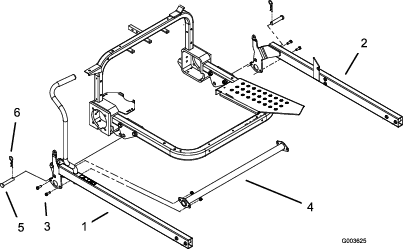
Mount the lift-arm foot pedal to the outside of the left lift arm with 2 bolts (3/8 x 3 inch) and 2 locknuts (3/8 inch).
Note: Position the foot pedal as shown in Figure 25.
-
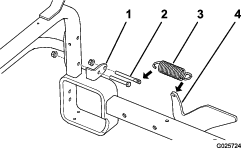
Remove the lower nut and bolt securing each hitch tube mounting bracket to the vertical frame tubes (Figure 26).
Note: Discard the nut and bolt.
-
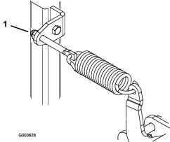
Using the open hitch tube mounting holes, secure a spring bracket to each hitch tube bracket/vertical frame tube with a bolt (3/8 x 2-3/4 inch) and a locknut (3/8 inch).
Note: Position the spring brackets as shown in Figure 26.
-
Pull back on the handle to raise and lock the blade into the transport position.
-
Tighten all remaining fasteners.
-
Connect the extension spring to the lift arm and to a spring rod.
-
Insert the spring rod into the hole in the spring bracket and loosely secure it with a locknut (3/8 inch).
-
Repeat steps 6 and 7 on the opposite side of the machine.
-
Install the rear tires and remove the blocks from under the rear of the machine.
Note: Torque the lug nuts to 61 to 75 N∙m (45 to 55 ft-lb).
Adjusting the Spring Tension
The spring adjustment controls the force that it takes to raise the blade to the transport position. If the spring is too loose, it will be hard to raise the blade to the transport position. However, too much spring tension causes the blade to float excessively during operation.
-
Lower the blade to the floor.
Note: When the springs are properly adjusted, the entire length of the bottom of the blade will be no more than 6 mm (1/4 inch) off the floor.
-
Rotate the spring adjusting nuts (Figure 27) clockwise to raise the blade or counterclockwise to lower the blade.
Operation
Operating the Blade
Pull back on the handle to raise and lock the blade into the transport position. Press the locking pedal to release the blade into the operating position.
You can use the blade to push or pull sand and dirt. With the blade in the operating position, simply push forward or pull back slightly on the handle or press on the lift arm foot pedal to control the plowing action.
Note: If the wheels spin while plowing, raise the blade slightly by pulling back on the handle. At times the engine may begin to overload. When it does, gradually release the traction pedal to increase the engine speed and power
Removing and Storing the Blade
-
Carefully remove the adjusting nuts securing the spring rods to the spring brackets.
Warning
If the springs are under tension, they could cause personal injury.
Carefully release pressure from components with stored energy.
-
Remove the spring rods and springs.
-
Lower the blade to the floor.
-
Remove the hairpin cotter pins and the clevis pins that connect the lift arms to the mounting brackets.
-
Raise the front of the machine and slide the complete blade assembly forward and away from the machine.