| Maintenance Service Interval | Maintenance Procedure |
|---|---|
| Before each use or daily |
|
Introduction
This rotary-blade, lawn mower is intended to be used by professional, hired operators. It is designed primarily for cutting grass on well-maintained lawns on residential or commercial properties. It is not designed for cutting brush or for agricultural uses.
Read this information carefully to learn how to operate and maintain your product properly and to avoid injury and product damage. This manual should be considered as part of the machine, as it contains, safety, operational and maintenance information. The mower is a precision built machine designed solely for cutting grass and similar low lying ground vegetation within the limitations stated in this manual. You are responsible for operating the product properly and safely.
You may contact Toro directly for product safety and operation training materials, accessory information, help finding a dealer, or to register your product at Toro Commercial Products Service Department Spellbrook, Bishops Stortford, CM23 4BU, England, +44(0)1279 603019, Email: uk.service@toro.com.
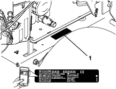
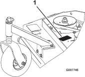
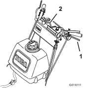
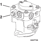
Whenever you need service, genuine Toro parts, or additional information, contact an Authorized Service Dealer or Toro Customer Service and have the model and serial numbers of your product ready. Figure 1 and Figure 2 identify the location of the model and serial numbers on the product. Write the numbers in the space provided.
Important: With your mobile device, you can scan the QR code on the serial number decal (if equipped) to access warranty, parts, and other product information.
This manual identifies potential hazards and has safety messages identified by the safety-alert symbol (Figure 3), which signals a hazard that may cause serious injury or death if you do not follow the recommended precautions.

This manual uses 2 words to highlight information. Important calls attention to special mechanical information and Note emphasizes general information worthy of special attention.
This product complies with all relevant European directives; for details, please see the separate product specific Declaration of Conformity (DOC) sheet.
Safety
Improper use or maintenance by the operator or owner can result in injury. To reduce the potential for injury, comply with these safety instructions and always pay attention to the safety-alert symbol, which means Caution, Warning, or Danger—personal safety instruction. Failure to comply with the instruction may result in personal injury or death.
This machine has been designed in accordance with EN ISO 5395:2013.
Safe Operating Practices
Training
-
Read the Operator's Manual and other training material.
-
If the operator(s) or mechanic(s) cannot read the manual language, it is the owner's responsibility to explain this material to them.
-
Become familiar with the safe operation of the equipment, operator controls, and safety signs.
-
All operators and mechanics should be trained. The owner is responsible for training the users.
-
Never let children or untrained people operate or service the equipment. Local regulations may restrict the age of the operator.
-
The owner/user can prevent and is responsible for accidents or injuries occurring to people, or damage to property.
Preparation
-
Evaluate the terrain to determine what accessories and attachments you need to properly and safely perform the job. Use only accessories and attachments approved by the manufacturer.
-
Wear appropriate clothing including eye protection, long plants, substantial slip-resistant footwear, and hearing protection. Tie back long hair and do not wear loose clothing or loose jewelry.
-
Inspect the area where you will use the equipment and remove all objects such as rocks, toys, and wire, which can be contacted by the machine.
-
Check that the operator-presence controls, safety switches, and shields are attached and functioning properly. Do not operate unless they are functioning properly.
Safe Handling of Fuels
-
Use extra care when handling fuel. They are flammable and vapors are explosive.
-
Extinguish all cigarettes, cigars, pipes, and other sources of ignition.
-
Use only an approved fuel container.
-
Do not remove the fuel cap or fill the fuel tank while the engine is running or hot.
-
Do not add or drain fuel in an enclosed space.
-
Do not store the machine or fuel container where there is an open flame, spark, or pilot light, such as on a water heater or other appliance.
-
If you spill fuel, do not attempt to start the engine; avoid creating any source of ignition until the fuel vapors have dissipated.
Operation
-
Use your full attention while operating the machine. Do not engage in any activity that causes distractions; otherwise, injury or property damage may occur.
-
Lightning can cause severe injury or death. If lightning is seen, or thunder is heard in the area, do not operate the machine; seek shelter.
-
Do not run an engine in an enclosed area.
-
Operate only in well-lit areas, keeping away from holes and hidden hazards.
-
Ensure that all drives are in neutral and that the parking brake is engaged before starting engine. Start the engine only from the operator’s position.
-
Make sure that you have good footing while using this machine, especially when backing up. Reduced footing could cause slipping.
-
Do not raise the mower deck with the blades running.
-
Do not operate the machine without the PTO shield or other guards securely in place. Be sure that all interlocks are attached, adjusted properly, and functioning properly.
-
Do not operate with the discharge deflector raised, removed or altered, unless you are using a grass catcher.
-
Do not change the engine governor setting or overspeed the engine.
-
Park the machine on a level surface, disengage drives, engage the parking brake, shut off the engine, and remove the key before leaving the operator's position for any reason, including emptying the catchers or unclogging the chute.
-
Stop the machine, shut off the engine, remove the key, and inspect the blades after striking objects or if an abnormal vibration occurs. Make the necessary repairs before resuming operation.
-
Keep your hands and feet away from the cutting unit.
-
Look behind and down before backing up to ensure a clear path.
-
Keep pets and bystanders away from an operating machine.
-
Slow down and use caution when making turns and crossing roads and sidewalks. Stop the blades if you are not mowing.
-
Be aware of the mower-discharge direction and do not point it at anyone.
-
Do not operate the machine while ill, tired, or under the influence of alcohol or drugs.
-
Use care when loading or unloading the machine into or from a trailer or truck.
-
Use care when approaching blind corners, shrubs, trees, or other objects that may obscure vision.
Slope Safety
-
Mow across the face of slopes; never up and down. Use extreme caution when changing direction on slopes.
-
Do not mow on excessively steep slopes. Poor footing could cause a slip-and-fall accident.
-
Mow with caution near drop-offs, ditches, or embankments.
Maintenance and Storage
-
Park the machine on a level surface, disengage drives, engage the parking brake, shut off the engine, and remove the key or disconnect spark-plug wire. Wait for all movement to stop before adjusting, cleaning, or repairing.
-
Clean grass and debris from the cutting unit, drives, mufflers, and engine to help prevent fires.
-
Clean up oil or fuel spills.
-
Let the engine cool before storing the machine.
-
Do not store fuel near flames or drain fuel indoors.
-
Do not allow untrained personnel to service the machine.
-
Use jack stands to support components when required.
-
Carefully release pressure from components with stored energy.
-
Disconnect the battery or remove the spark-plug wire before making any repairs. Disconnect the negative terminal first and the positive terminal last. Connect the positive terminal first and negative last.
-
Use care when checking the blades. Wrap the blade(s) or wear thickly padded gloves, and use caution when servicing them. Only replace blades; do not straighten or weld them.
-
Keep hands and feet away from moving parts. If possible, do not make adjustments with the engine running.
-
Keep all parts in good working condition and all hardware tightened. Replace all worn or damaged decals.
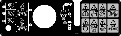
Safety and Instructional Decals
 |
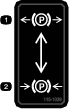
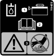
Safety decals and instructions are easily visible to the operator and are located near any area of potential danger. Keep safety signs clear and visible, replace any decal that is damaged or missing. |


.png)


Setup
Note: Determine the left and right sides of the machine from the normal operating position.
Checking the Fluids and Tire Pressure
-
Before you start the engine and use the machine, check the oil level in the engine crankcase; refer to Checking the Engine-Oil Level.
-
Check the grease for the machine and mower deck.
Note: The cutting blades are set to a 51 mm (2 inch) height of cut at initial purchase. The axle position is B, with 2 spaces below the casters and 4 spaces below the spindle.
Installing the Wheel Kit
Parts needed for this procedure:
| Wheel Kit (sold separately) | 1 |
Refer to the Installation Instructions for the wheel kit
Reading the Manual and Viewing the Operator Training Material
Parts needed for this procedure:
| Operator's Manual | 1 |
| Engine owner’s manual | 1 |
| Operator training material | 1 |
| Oil-drain hose | 1 |
-
Read the Operator's Manual.
-
View the operator training material before operating the machine. This is general training material and the machine may differ from that supplied.
-
Use the oil-drain hose when changing the engine oil.
Product Overview
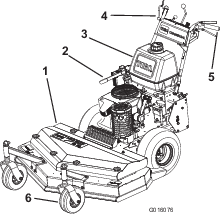
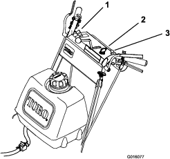
Become familiar with all the controls (Figure 5) before you start the engine and operate the machine.
Control Panel
Throttle Control
The throttle controls the engine speed and has 2 positions: SLOW and FAST.
Operator-Presence Control (OPC) Levers
When you squeeze the OPC levers against the handles, the OPC system senses that you are in the normal operating position. When you release the OPC levers, the OPC system senses that you have left the normal operating position, and the system shuts off the engine if either the speed-control lever is not in the NEUTRAL position or the blade-control (PTO) knob is engaged.
Blade-Control Knob (PTO)
Use the blade-control knob (PTO), with the OPC levers pressed against the handles, to engage and disengage the drive belt to drive the mower blades. Pull the knob up to engage the blades and push down to disengage the blades.
Key Switch
This switch is used in conjunction with recoil starter and has 3 positions: OFF, RUN, and START.
Speed-Control Lever
This machine has a variable speed control with a NEUTRAL position. This controls how fast the machine travels.
Drive Levers
Release the drive levers to drive the machine forward; squeeze the levers until you feel an increase in force to go into the NEUTRAL position and then continue to squeeze them to drive the machine in reverse. Squeeze the right drive lever to turn right and squeeze the left lever to turn left.
Neutral Lock
Squeeze the drive levers until you feel an increase in force and move locks to the rear for neutral lock.
Fuel-Shutoff Valve
Close the fuel-shutoff valve when transporting or storing the machine.
Choke Control
Use the choke control to start a cold engine.
Note: Specifications and design are subject to change without notice.
| Cutting width | 82 cm (32 inches) |
| Width | 89 cm (35 inches) |
| Length | 203 cm (80 inches) |
| Height | 112 cm (44 inches) |
| Weight | 231 kg (509 lb) |
| Cutting width | 91 cm (36 inches) |
| Width | 94 cm (37 inches) |
| Length | 203 cm (80 inches) |
| Height | 112 cm (44 inches) |
| Weight | 232 kg (511 lb) |
| Cutting width | 122 cm (48 inches) |
| Width | 126 cm (49-1/2 inches) |
| Length | 194 cm (76-1/2 inches) |
| Height | 112 cm (44 inches) |
| Weight | 248 kg (547 lb) |
Attachments/Accessories
A selection of Toro approved attachments and accessories is available for use with the machine to enhance and expand its capabilities. Contact your Authorized Service Dealer or Distributor or go to www.Toro.com for a list of all approved attachments and accessories.
To ensure optimum performance and continued safety certification of the machine, use only genuine Toro replacement parts and accessories. Replacement parts and accessories made by other manufacturers could be dangerous, and such use could void the product warranty.
Operation
Adding Fuel
Fuel Safety
-
To avoid personal injury or property damage, use extreme care in handling fuel. Fuel vapors are flammable and explosive.
-
Extinguish all cigarettes, cigars, pipes, and other sources of ignition.
-
Use only an approved fuel container.
-
Do not remove the fuel cap or add fuel to the fuel tank while the engine is running or while hot.
-
Do not refuel the machine indoors.
-
Do not store the machine or fuel container where there is an open flame, spark, or pilot light, such as on a water heater or on other appliances.
-
Do not fill containers inside a vehicle or on a truck or trailer bed with a plastic liner. Always place containers on the ground, away from your vehicle before filling.
-
Remove the equipment from the truck or trailer and refuel it while it is on the ground. If this is not possible, then refuel from a portable container rather than a fuel-dispenser nozzle.
-
Do not operate the machine without the entire exhaust system in place and in proper working condition.
-
Keep the fuel-dispenser nozzle in contact with the rim of the fuel tank or container opening at all times until fueling is complete. Do not use a nozzle lock-open device.
-
If you spill fuel on your clothing, change your clothing immediately. Wipe up any fuel that spills.
-
Never overfill the fuel tank. Replace the fuel cap and tighten it securely.
-
Store fuel in an approved container and keep it out of the reach of children. Never buy more than a 30-day supply of fuel.
-
Do not fill the fuel tank completely full. Add fuel to the fuel tank until the level is 6 to 13 mm (1/4 to 1/2 inch) below the bottom of the filler neck. This empty space in the tank allows fuel to expand.
-
Avoid prolonged breathing of vapors.
-
Keep your face away from the nozzle and fuel tank opening.
-
Avoid contact with skin; wash off spills with soap and water.
-
Recommended Fuel
-
For best results, use only clean, fresh (less than 30 days old), unleaded gasoline with an octane rating of 87 or higher ((R+M)/2 rating method).
-
Ethanol: Gasoline with up to 10% ethanol (gasohol) or 15% MTBE (methyl tertiary butyl ether) by volume is acceptable. Ethanol and MTBE are not the same. Gasoline with 15% ethanol (E15) by volume is not approved for use. Never use gasoline that contains more than 10% ethanol by volume, such as E15 (contains 15% ethanol), E20 (contains 20% ethanol), or E85 (contains up to 85% ethanol). Using unapproved gasoline may cause performance problems and/or engine damage which may not be covered under warranty.
-
Do not use gasoline containing methanol.
-
Do not store fuel either in the fuel tank or fuel containers over the winter unless you use a fuel stabilizer.
-
Do not add oil to gasoline.
Using Stabilizer/Conditioner
Use fuel stabilizer/conditioner in the machine to keep the fuel fresh longer when used as directed by the fuel-stabilizer manufacturer.
Important: Do not use fuel additives containing methanol or ethanol.
Add the amount of fuel stabilizer/conditioner to fresh fuel as directed by the fuel-stabilizer manufacturer.
Filling the Fuel Tank
-
Park the machine on a level surface.
-
Engage the parking brake.
-
Shut off the engine and remove the key.
-
Clean around the fuel-tank cap.
-
Fill the fuel tank until the level is 6 to 13 mm (1/4 to 1/2 inch) below the bottom of the filler neck.
Note: This space in the tank allows the fuel to expand. Do not fill the fuel tank completely full.
-
Install the fuel tank cap securely. Wipe up any fuel that may have spilled.
Think Safety First
Carefully read all the safety instructions and decals in the safety section. Knowing this information could help you or any bystanders avoid injury.
Caution
This machine produces sound levels in excess of 85 dBA at the operator's ear and can cause hearing loss through extended periods of exposure.
Wear hearing protection when operating this machine.

Operating the Parking Brake
Always engage the parking brake when you stop the machine or leave it unattended.
Engaging the Parking Brake
Park the machine on a level surface.
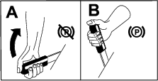
Disengaging the Parking Brake
Starting the Engine
-
Connect the wires to the spark plugs.
-
Open the fuel valve.
-
Disengage the blade-control knob (PTO) and move the speed-control lever to the NEUTRAL position.
-
Move the drive levers to the NEUTRAL position and engage the neutral locks.
-
Engage the parking brake.
-
Turn the key to the RUN position (Figure 5).
-
To start a cold engine, move the throttle control midway between the FAST and SLOW positions.
-
To start a warm engine, move the throttle control to the FAST position.
-
Engage the choke if the engine is cold (Figure 5).
Note: A warm or hot engine usually does not require any choking.
-
Turn the key to the START position to energize the starter. When the engine starts, release the key.
Note: Do not engage the starter for more than 5 seconds at a time. If the engine fails to start, allow for a 15 second cool-down period between attempts. Failure to follow these instructions can burn out the starter motor.
-
Disengage the choke as the engine warms up (Figure 9).
-
If the engine is cold, allow it to warm up and then move the throttle control to the FAST position.
Shutting Off the Engine
Important: In an emergency, you can shut off the engine immediately by turning the key to the OFF position.
-
Move the drive levers to the NEUTRAL position and engage the neutral locks.
-
Move the throttle lever to the SLOW (Figure 9).
-
Disengage the blade-control knob (PTO) and move the speed-control lever to the NEUTRAL position.
-
Let the engine idle for 30 to 60 seconds
-
Turn the key to the OFF position.
-
Engage the parking brake and remove the key.
Important: Close the fuel-shutoff valve before transporting or the storing the machine to prevent fuel leakage.
Operating the Neutral Locks
Always engage the neutral lock when you stop the machine. Engage the parking brake if it is left unattended.
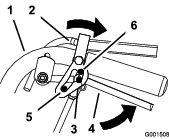
Setting the Neutral Lock
-
Squeeze the drive levers until you feel an increase in force.
-
Place your thumbs on the upper part of the locks and move them back until the pins are in the NEUTRAL position (Figure 10).
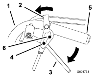
Releasing the Neutral Lock
-
Squeeze the drive levers until you feel an increase in force.
-
Place your thumbs on the upper part of locks and move them forward until the pins are in the forward slot (Figure 11).
Operating the Blade-Control Knob (PTO)
The blade-control knob (PTO) is used in conjunction with the operator-presence control (OPC) levers to engage and disengage the mower blades.
Engaging the Mower Blades (PTO)
-
To engage the mower blades, squeeze the operator-presence control (OPC) levers against handle grips (Figure 12).
-
Pull the blade-control knob (PTO) up. Hold the OPC levers against handle grip.
Note: Releasing the OPC levers with the mower blades running shuts off the engine.
-
Start the engine and repeat the procedure to engage the mower blades if the operator-presence control (OPC) levers are released.

Disengaging the Mower Blades (PTO)
Using the Safety-Interlock System
Caution
If safety-interlock switches are disconnected or damaged the machine could operate unexpectedly causing personal injury.
-
Do not tamper with the interlock switches.
-
Check the operation of the interlock switches daily and replace any damaged switches before operating the machine.
Understanding the Safety-Interlock System
The safety-interlock system is designed to prevent the machine from starting unless:
-
The blade-control knob (PTO) is disengaged.
-
The speed-control lever is in the NEUTRAL position.
The safety-interlock system is designed to shut off the engine when:
-
The operator-presence control (OPC) levers are released with the mower blades engaged and/or the speed-control lever out of the NEUTRAL position.
-
The speed-control lever is shifted out of the NEUTRAL without holding OPC levers or with the brake engaged.
-
The blade-control knob (PTO) is pulled up without holding the OPC levers.
Testing the Safety-Interlock System
Test the safety-interlock system before you use the machine each time. If the safety system does not operate as described, have an Authorized Service Dealer repair the safety system immediately.
Warning
While testing the safety-interlock system, the machine may move forward and cause personal injury or property damage.
-
Test the safety-interlock system in an open area.
-
Ensure that no one is standing in front of the machine while testing the safety-interlock system.
-
Engage the neutral locks and move the speed-control lever to the NEUTRAL position.
-
Start the engine; refer to Starting the Engine.
-
Without holding the operator-presence control (OPC) levers, pull the blade-control knob (PTO) up. The engine should shut off.
-
Disengage the blade-control knob (PTO).
-
With engine running, hold down the OPC levers. Pull the blade-control knob (PTO) up. The drive belt should engage and the mower blades begin rotating.
-
Release the OPC levers. The engine should shut off.
-
With the engine running, move the speed-control lever forward. Release the OPC levers. The engine should shut off.
-
If all the above conditions are not met have an Authorized Service Dealer repair the safety system immediately.
Driving the Machine Forward and Backward
The throttle control regulates the engine speed as measured in rpm (revolutions per minute). Place the throttle control in the FAST position for best mowing performance.
Driving Forward
-
Disengage the parking brake.
-
Move the speed-control lever to desired speed.
-
Release the neutral lock. Refer to Releasing the Neutral Lock.
-
Slowly release the drive levers to move forward (Figure 13).
To go straight, release drive levers equally (Figure 13).
To turn, squeeze the drive lever on the side and direction you want to turn (Figure 13).
Driving Backward
Slowly squeeze the drive levers to the handle to move rearward (Figure 13).
Bringing the Machine to Neutral
Always engage the neutral lock and parking brake when you stop the machine.
-
Squeeze the drive levers to the NEUTRAL position.
-
Engage the neutral locks. Refer to Operating the Neutral Locks.
-
Move the speed-control lever to the NEUTRAL position.
Pushing the Machine by Hand
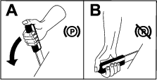
The bypass valves enable you to push the machine by hand without the engine running.
Important: Always push the machine by hand. Never tow the machine, because hydraulic damage may occur.
To Push the Machine
-
Park the machine on a level surface, disengage the PTO, and engage the parking brake.
-
Shut off the engine, remove the key, and wait for all moving parts to stop before leaving the operating position.
-
Open the bypass valves by turning them counter clockwise 1 to 2 times (Figure 14).
Note: This allows hydraulic fluid to bypass the pumps and the wheels to turn.
-
Disengage the parking brake.
-
Push the machine to the desired location.
-
Engage the parking brake.
-
Close the bypass valves but do not overtighten them.
Note: Rotate the bypass valves a maximum of 2 turns so the valve does not come out of the body and cause fluid to run out.
Important: Do not start or operate the machine with the bypass valves open. Damage to system may occur.
Transporting the Machine
Use a heavy-duty trailer or truck to transport the machine. Ensure that the trailer or truck has all necessary lighting and marking as required by law. Please carefully read all the safety instructions. Knowing this information could help you, your family, pets or bystanders avoid injury.
-
Secure a trailer to towing vehicle with safety chains.
-
Shut off the engine, remove the key, and wait for all moving parts to stop before leaving the operating position.
-
Securely fasten the machine to the trailer or truck with straps, chains, cable, or ropes.
Adjusting the Height of Cut
This machine has a 26 to 108 mm (1 to 4-1/4 inch) range for height of cut. Adjust the blade spacers, rear axle height or front caster spacers to get the correct height of cut. Refer to Height-of-Cut Chart to select the combination of adjustments required.
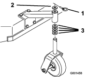
Adjusting the Blade Height
Adjust the blades by using the 4 spacers (1/4 inch) spacers on the blade spindle bolts. This allows for a 25 mm (1 inch) adjustment range of cutting height, in 6 mm (1/4 inch) increments, in any axle position. Use the same number of blade spacers on all blades to achieve a level cut (2 above and 2 below, 1 above and 3 below, etc.).
-
Park the machine on a level surface, disengage the PTO, and engage the parking brake.
-
Shut off the engine, remove the key, and wait for all moving parts to stop before leaving the operating position.
-
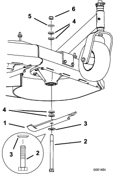
Hold the blade bolt and remove the nut. Slide the bolt down through the spindle, and change the spacers as needed (Figure 15).
-
Install the bolt, curved washer, blade, add extra spacers, and secure them with a thin washer and a nut (Figure 15).
-
Torque the blade bolt to 101 to 108 N∙m (75 to 80 ft-lb).
Adjusting the Axle Height
Adjust the axle position to the selected height-of-cut setting. Refer to Height-of-Cut Chart.
-
Park the machine on a level surface, disengage the PTO, and engage the parking brake.
-
Shut off the engine, remove the key, and wait for all moving parts to stop before leaving the operating position.
-
Place a jack under the engine frame. Raise the back end of the engine frame enough to remove the drive wheels.
-
Remove the drive wheels.
-
Loosen, but do not remove, the 2 top axle bolts (Figure 16).
-
Remove the 2 lower axle bolts (Figure 16).
-
Raise or lower the mounting bracket, so that you can install the 2 axle adjustment bolts in the desired hole location (Figure 16).
Note: A tapered punch can be used to help align the holes.
-
Tighten all 4 bolts.
-
Install the drive wheels and lower the machine.
Adjusting the Caster Position
-
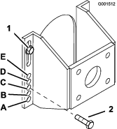
Adjust the caster spacers to match with the axle hole selected (Figure 17); refer to Height-of-Cut Chart and .
-
Remove the latch pin, slide the caster from the support, and change the spacers (Figure 17).
-
Install the caster in the support and insert the latch pin (Figure 17).
Adjusting the Handle Height
The handle position can be adjusted to match your height preference.
-
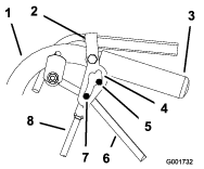
Remove the hairpin cotters and clevis pins from the drive levers and neutral locks (Figure 18).
-
Loosen the upper flange bolts (3/8 x 1-1/4 inches) and flange nut securing handle to rear frame (Figure 19).
-
Remove the lower flange bolts (3/8 x 1 inch) and flange nuts securing handle to rear frame (Figure 19).
-
Pivot handle to desired operating position and install lower flange bolts (3/8 x 1 inch) and flange nuts into mounting holes. Tighten all flange bolts.
-
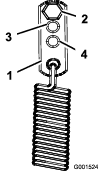
Adjust the control rod length by rotating the control rod in the rod fitting (Figure 18 and Figure 19).
-
Install hairpin cotter between drive levers and neutral locks and into clevis pins (Figure 18).
Note: Make sure that the clevis pins are inserted into the neutral locks.
-
Perform the hydraulic linkage adjustments when the handle height is changed; refer Adjusting the Hydraulic Control Linkages.
Height-of-Cut Chart
| Axle Position | Number of spacers below caster | Number of 6 mm (1/4 inch) blade spacers below spindle | |||||
| 13 mm | 5 mm | 4 | 3 | 2 | 1 | 0 | |
| (1/2 inch) | (3/16 inch) | ||||||
| A | 0 | 0 | 26 mm | 32 mm | 38 mm | 45 mm | 51 mm |
| (1 inch) | (1-1/4 inch) | (1-1/2 inch) | (1-3/4 inch) | (2 inch) | |||
| A | 0 | 1 | 29 mm | 35 mm | 41 mm | 48 mm | 54 mm |
| (1-1/8 inch) | (1-3/8 inch) | (1-5/8 inch) | (1-7/8 inch) | (2-1/8 inch) | |||
| A | 1 | 0 | 35 mm | 41 mm | 48 mm | 54 mm | 60 mm |
| (1-3/8 inch) | (1-5/8 inch) | (1-7/8 inch) | (2-1/8 inch) | (2-3/8 inch) | |||
| B | 0 | 1 | 35 mm | 41 mm | 48 mm | 54 mm | 60 mm |
| (1-3/8 inch) | (1-5/8 inch) | (1-7/8 inch) | (2-1/8 inch) | (2-3/8 inch) | |||
| B | 1 | 0 | 41 mm | 48 mm | 54 mm | 60 mm | 67 mm |
| (1-5/8 inch) | (1-7/8 inch) | (2-1/8 inch) | (2-3/8 inch) | (2-5/8 inch) | |||
| B | 1 | 1 | 45 mm | 51 mm | 57 mm | 64 mm | 70 mm |
| (1-3/4 inch) | (2 inch) | (2-1/4 inch) | (2-1/2 inch) | (2-3/4 inch) | |||
| B | 2 | 0 | 51 mm | 57 mm | 64 mm | 70 mm | 76 mm |
| (2 inch) | (2-1/4 inch) | (2-1/2 inch) | (2-3/4 inch) | (3 inch) | |||
| C | 1 | 1 | 48 mm | 54 mm | 60 mm | 67 mm | 73 mm |
| (1-7/8 inch) | (2-1/8 inch) | (2-3/8 inch) | (2-5/8 inch) | (2-7/8 inch) | |||
| C | 2 | 0 | 54 mm | 60 mm | 67 mm | 73 mm | 79 mm |
| (2-1/8 inch) | (2-3/8 inch) | (2-5/8 inch) | (2-7/8 inch) | (3-1/8 inch) | |||
| C | 2 | 1 | 57 mm | 64 mm | 70 mm | 76 mm | 83 mm |
| (2-1/4 inch) | (2-1/2 inch) | (2-3/4 inch) | (3 inch) | (3-1/4 inch) | |||
| C | 3 | 0 | 64 mm | 70 mm | 76 mm | 83 mm | 89 mm |
| (2-1/2 inch) | (2-3/4 inch) | (3 inch) | (3-1/4 inch) | (3-1/2 inch) | |||
| D | 2 | 1 | 60 mm | 67 mm | 73 mm | 79 mm | 86 mm |
| (2-3/8 inch) | (2-5/8 inch) | (2-7/8 inch) | (3-1/8 inch) | (3-3/8 inch) | |||
| D | 3 | 0 | 64 mm | 70 mm | 76 mm | 83 mm | 89 mm |
| (2-1/2 inch) | (2-3/4 inch) | (3 inch) | (3-1/4 inch) | (3-1/2 inch) | |||
| D | 3 | 1 | 70 mm | 76 mm | 83 mm | 89 mm | 95 mm |
| (2-3/4 inch) | (3 inch) | (3-1/4 inch) | (3-1/2 inch) | (3-3/4 inch) | |||
| D | 4 | 0 | 76 mm | 83 mm | 89 mm | 95 mm | 102 mm |
| (3 inch) | (3-1/4 inch) | (3-1/2 inch) | (3-3/4 inch) | (4 inch) | |||
| E | 3 | 1 | 73 mm | 79 mm | 86 mm | 92 mm | 98 mm |
| (2-7/8 inch) | (3-1/8 inch) | (3-3/8 inch) | (3-5/8 inch) | (3-7/8 inch) | |||
| E | 4 | 0 | 79 mm | 86 mm | 92 mm | 98 mm | 105 mm |
| (3-1/8 inch) | (3-3/8 inch) | (3-5/8 inch) | (3-7/8 inch) | (4-1/8 inch) | |||
| E | 4 | 1 | 83 mm | 89 mm | 95 mm | 102 mm | 108 mm |
| (3-1/4 inch) | (3-1/2 inch) | (3-3/4 inch) | (4 inch) | (4-1/4 inch) | |||
Maintenance
Note: Determine the left and right sides of the machine from the normal operating position.
Recommended Maintenance Schedule(s)
| Maintenance Service Interval | Maintenance Procedure |
|---|---|
| After the first 8 hours |
|
| After the first 25 hours |
|
| Before each use or daily |
|
| Every 25 hours |
|
| Every 50 hours |
|
| Every 100 hours |
|
| Every 200 hours |
|
| Every 300 hours |
|
| Every 400 hours |
|
| Before storage |
|
Important: Refer to the engine owner’s manual for additional maintenance procedures.
Caution
If you leave the key in the switch, someone could accidently start the engine and seriously injure you or other bystanders.
Remove the key from the switch before you perform any maintenance.
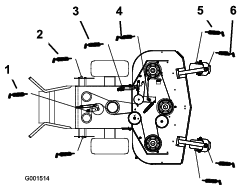
Lubrication
Use Figure 20 for locating the grease points on the machine.
Grease type: No. 2 lithium or molybdenum grease
-
Park the machine on a level surface, disengage the PTO, and engage the parking brake.
-
Shut off the engine, remove the key, and wait for all moving parts to stop before leaving the operating position.
-
Clean the grease fittings with a rag. Scrape any paint off the front of the fitting(s).
-
Connect a grease gun to the fitting. Pump grease into the fittings until grease begins to ooze out of the bearings.
-
Wipe up any excess grease.
Lubricating the Caster and Wheel Bearings
| Maintenance Service Interval | Maintenance Procedure |
|---|---|
| Before each use or daily |
|
Lubricate the front wheel bearings and front spindles (Figure 20).
Greasing the Mower-Belt Idler
| Maintenance Service Interval | Maintenance Procedure |
|---|---|
| Every 50 hours |
|
Grease the fitting on the mower-belt idler arm pivot (Figure 20).
Note: Remove the mower deck cover to access the grease fitting for the mower-belt idler arm.
Greasing the Pump Control and Bell Crank
| Maintenance Service Interval | Maintenance Procedure |
|---|---|
| Every 50 hours |
|
| Every 100 hours |
|
| Every 400 hours |
|
Grease the fitting on the pump-drive idler pivot and the pump control.
Grease the blade engagement (PTO) bellcrank (Figure 20).
Lubricate cam lock with anti-seize compound.
Note: Remove the guards fitted under the machine to access the grease fitting on the pump-drive idler pivot.
Engine Maintenance
Servicing the Air Cleaner
| Maintenance Service Interval | Maintenance Procedure |
|---|---|
| Every 25 hours |
|
| Every 50 hours |
|
| Every 200 hours |
|
Inspect the foam and paper elements and replace them if they are damaged or excessively dirty.
Important: Do not oil the foam or paper element.
Removing the Foam and Paper Elements
-
Park the machine on a level surface, disengage the PTO, and engage the parking brake.
-
Shut off the engine, remove the key, and wait for all moving parts to stop before leaving the operating position.
-
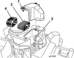
Clean around the air cleaner to prevent dirt from getting into the engine and causing damage (Figure 21).
-
Unscrew the cover knobs and remove the air-cleaner cover (Figure 21).
-
Unscrew the hose clamp and remove the air-cleaner assembly (Figure 21).
-
Carefully pull the foam element off the paper element (Figure 21).
Cleaning the Foam Air-Cleaner Element
-
Wash the foam element in liquid soap and warm water. When the element is clean, rinse it thoroughly.
-
Dry the element by squeezing it in a clean cloth.
Important: Replace the foam element if it is torn or worn.
Servicing the Paper Air-Cleaner Element
-
Do not clean the paper filter. Replace it (Figure 21).
-
Inspect the element for tears, an oily film, or damage to the rubber seal.
-
Replace the paper element if it is damaged.
Installing the Foam and Paper Elements
Important: To prevent engine damage, always operate the engine with the complete foam and paper air-cleaner assembly installed.
Servicing the Engine Oil
| Maintenance Service Interval | Maintenance Procedure |
|---|---|
| Every 300 hours |
|
Engine Oil Specifications
Oil Capacity: with a filter change—1.7 L (57 fl oz); without a filter change—1.5 L (51 fl oz)
Viscosity: See the table below.

Checking the Engine-Oil Level
| Maintenance Service Interval | Maintenance Procedure |
|---|---|
| Before each use or daily |
|
Note: Check the oil when the engine is cold.
Important: If you overfill or underfill the engine crankcase with oil and run the engine, you may damage the engine.
-
Park the machine on a level surface, disengage the PTO, and engage the parking brake.
-
Shut off the engine, remove the key, and wait for all moving parts to stop before leaving the operating position.
Note: Ensure that the engine is cool so that the oil has had time to drain into the sump.
-
To keep dirt, grass clippings, etc., out of the engine, clean the area around the oil-fill cap and dipstick before removing it (Figure 23).
Changing the Engine Oil
| Maintenance Service Interval | Maintenance Procedure |
|---|---|
| After the first 8 hours |
|
| Every 100 hours |
|
-
Park the machine so that the drain side is slightly lower than the opposite side to ensure that the oil drains completely.
-
Disengage the PTO and engage the parking brake.
-
Shut off the engine, remove the key, and wait for all moving parts to stop before leaving the operating position.
-
Drain the oil from the engine (Figure 24).
-
Slowly pour approximately 80% of the specified oil into the filler tube and slowly add the additional oil to bring it to the Full mark (Figure 25).
-
Dispose of the used oil at a recycling center.
Changing the Engine-Oil Filter
| Maintenance Service Interval | Maintenance Procedure |
|---|---|
| Every 200 hours |
|
-
Drain the oil from the engine; refer to Changing the Engine Oil.
-
Change the engine-oil filter (Figure 26).
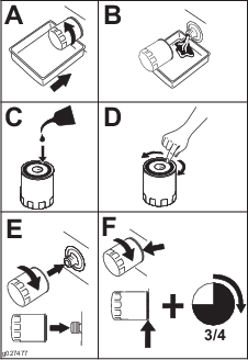
Note: Ensure that the oil-filter gasket touches the engine, and then turn the oil filter an extra 3/4 turn.
-
Fill the crankcase with the proper type of new oil (Figure 25).
Servicing the Spark Plug
| Maintenance Service Interval | Maintenance Procedure |
|---|---|
| Every 100 hours |
|
Ensure that the air gap between the center and side electrodes is correct before installing the spark plug. Use a spark plug wrench for removing and installing the spark plug and a gapping tool or feeler gauge to check and adjust the air gap. Install a new spark plug if necessary.
Type of Spark Plug: NGK® BPR4ES or equivalent
Air Gap: 0.75 mm (0.03 inch)
Removing the Spark Plug
-
Park the machine on a level surface, disengage the PTO, and engage the parking brake.
-
Shut off the engine, remove the key, and wait for all moving parts to stop before leaving the operating position.
-
Clean the area around the base of the plug to keep dirt and debris out of the engine.
-
Remove the spark plug (Figure 27).
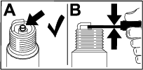
Checking the Spark Plug
Important: Do not clean the spark plug(s). Always replace the spark plug(s) when it has a black coating, worn electrodes, an oily film, or cracks.
If you see light brown or gray on the insulator, the engine is operating properly. A black coating on the insulator usually means the air cleaner is dirty.
Set the gap to 0.75 mm (0.03 inch).
Installing the Spark Plug
Fuel System Maintenance
Servicing the Fuel Tank
Danger
In certain conditions, fuel is extremely flammable and highly explosive. A fire or explosion from fuel can burn you and others and can damage property.
-
Drain fuel from the fuel tank when the engine is cold. Do this outdoors in an open area. Wipe up any fuel that spills.
-
Never smoke when draining fuel, and stay away from an open flame or where a spark may ignite the fuel fumes.
Draining the Fuel Tank
-
Park the machine on a level surface, disengage the PTO, and engage the parking brake.
-
Shut off the engine, remove the key, and wait for all moving parts to stop before leaving the operating position.
-
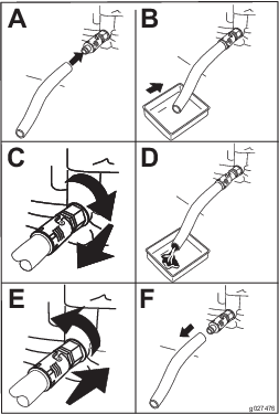
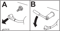
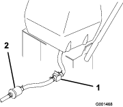
Close the fuel-shutoff valve at the fuel tank (Figure 30).
-
Squeeze the ends of the hose clamp together and slide it up the fuel line away from fuel filter (Figure 30).
-
Pull the fuel line off the fuel filter (Figure 30). Open the fuel-shutoff valve and allow the fuel to drain into a fuel can or drain pan.
Note: Now is the best time to install a new fuel filter because the fuel tank is empty. Refer to Replacing the Fuel Filter.
-
Install the fuel line onto the fuel filter. Slide the hose clamp close to the valve to secure the fuel line.
Servicing the Fuel Filter
Replacing the Fuel Filter
| Maintenance Service Interval | Maintenance Procedure |
|---|---|
| Every 200 hours |
|
Never install a dirty filter after removing it from the fuel line.
-
Park the machine on a level surface, disengage the PTO, and engage the parking brake.
-
Shut off the engine, remove the key, and wait for all moving parts to stop before leaving the operating position.
-
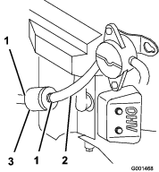
Close fuel-shutoff valve at the fuel tank (Figure 30).
-
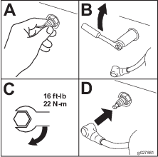
Squeeze the ends of the hose clamps together and slide them away from the filter (Figure 31).
Note: Note how the fuel filter is installed in order to install the new filter correctly.
-
Remove the filter from the fuel lines.
-
Install a new filter and move the hose clamps close to the filter.
-
Open fuel-shutoff valve at fuel tank (Figure 30).
-
Check for fuel leaks and repair if needed.
-
Wipe up any spilled fuel.
Drive System Maintenance
Perform the following linkage adjustments, Adjusting the Speed-Control Linkage through Adjusting the Tracking , when the machine needs maintenance. If any adjustment is needed, do them in the order that they are listed.
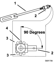
Adjusting the Speed-Control Linkage
-
Park the machine on a level surface, disengage the PTO, and engage the parking brake.
-
Shut off the engine, remove the key, and wait for all moving parts to stop before leaving the operating position.
-
Move the speed-control lever (located on the console) to the full forward position.
-
Check the orientation of the tabs on the ends of the speed control crank. Ensure that these tabs are pointing straight down at the 6 o'clock position approximately (Figure 32).
-
Adjust the threaded yoke at the bottom of the speed-control linkage until the tabs are at the 6 o'clock position (Figure 32).
-
Pull the speed-control lever back to the NEUTRAL position.
-
Check to make sure that the safety switch is pressed and there is a 8 mm (5/16 inch) space between the actuating tab and the switch (Figure 33).
-
If needed, adjust switch location to create the 8 mm (5/16 inch) space (Figure 33).
Adjusting the Neutral Control Linkages
Warning
The engine must be running when you perform the control linkage adjustments. Contact with moving parts or hot surfaces may cause personal injury.
Keep your hands, feet, face, clothing and other body parts away from rotating parts, muffler and other hot surfaces.
Warning
Mechanical or hydraulic jacks may fail to support machine and cause a serious injury.
-
Use jack stands when supporting machine.
-
Do not use hydraulic jacks.
-
Park the machine on a level surface, disengage the PTO, and engage the parking brake.
-
Shut off the engine, remove the key, and wait for all moving parts to stop before leaving the operating position.
-
Raise the rear of the machine onto jack stands to raise the drive wheels off the ground.
-
Disengage the parking brake.
-
Start the engine and move the throttle to the full throttle position.
-
Place the neutral locks in the full forward position and move the speed-control lever to the medium-speed position.
-
Hold OPC levers down.
Note: Hold the OPC levers down whenever the speed-control lever is out of the NEUTRAL position or the engine will shut off.
Warning
The electrical system does not perform proper safety shut off with the operator-presence control (OPC) levers held down in place.
-
Make sure that the operator-presence control (OPC) levers are working when adjustment is completed.
-
Never operate this unit with the operator-presence control (OPC) levers held down in place.
-
-
Squeeze 1 drive lever until you feel an increased resistance. This is the NEUTRAL position.
Note: Make sure that you have not reached the end of the neutral lock slot. If you have, shorten the control lever linkage. Refer to Adjusting the Control Rod.
-
If the wheel turns while holding the drive lever in the NEUTRAL, the neutral control linkages need adjustment (Figure 34). If the wheel stops then go to step 12.
-
Loosen the nut against the neutral control linkage yoke (Figure 34).
-
Adjust the neutral control linkage until the respective drive wheel stops while the drive lever is pulled against the neutral spring (NEUTRAL position) (Figure 34).
-
Turn the adjusting bolt approximately 1/4 turn clockwise if the wheel is turning in reverse or turn the bolt approximately 1/4 turn counter-clockwise if the wheel is turning forward (Figure 34).
-
Release the drive lever to the forward drive position and squeeze back into the NEUTRAL position. Check to see if the wheel stops. If not, repeat the above adjustment procedure.
-
After adjustments are made, tighten the nuts against the yokes.
-
Repeat this procedure for the opposite side.
Adjusting the Hydraulic Control Linkages
Warning
The engine must be running when you perform the control linkage adjustments. Contact with moving parts or hot surfaces may cause personal injury.
Keep your hands, feet, face, clothing and other body parts away from rotating parts, muffler and other hot surfaces.
Warning
Mechanical or hydraulic jacks may fail to support machine and cause a serious injury.
-
Use jack stands when supporting machine.
-
Do not use hydraulic jacks.
Adjusting the Left Side Linkage
-
Park the machine on a level surface, disengage the PTO, and engage the parking brake.
-
Shut off the engine, remove the key, and wait for all moving parts to stop before leaving the operating position.
-
Raise the rear of the machine onto jack stands high enough to raise the drive wheels of the ground.
-
Disengage the parking brake.
-
Start the engine and move the throttle to the full throttle position.
-
Place the left drive lever in the full forward position.
-
Place the speed-control lever in the NEUTRAL position.
Warning
The electrical system does not perform proper safety shut off with the operator-presence control (OPC) levers held down in place.
-
Make sure that the operator-presence control (OPC) levers are working when adjustment is completed.
-
Never operate this unit with the operator-presence control (OPC) levers held down in place.
-
-
Loosen the front adjusting nut on left hydraulic control linkage as shown in Figure 36.
-
Turn the left rear adjusting nut counter-clockwise until wheel rotates forward (Figure 36).
-
Turn the rear adjusting nut clockwise 1/4 turn at a time. Then move the speed-control lever forward and back to the NEUTRAL position. Repeat this until left wheel stops rotating forward (Figure 36).
-
Turn the rear nut an additional 1/2 turn and tighten the front adjusting nut.
Note: Make sure that the flat part of linkage is perpendicular to pin part of swivel (Figure 35).
-
After adjusting the left hydraulic control linkage, move the speed-control lever forward and then back to the NEUTRAL position.
-
Hold the OPC levers down.
Note: Hold the OPC levers down whenever the speed-control lever is out of the NEUTRAL position or the engine will shut off.
-
Make sure that the speed-control lever is in the NEUTRAL position and the tire does not rotate.
-
Repeat the adjustment if needed.
Note: If inconsistent neutral occurs, ensure that both springs are properly tightened on the speed-control lever under the console, especially the rear pivot spring. Repeat the adjustments above if necessary (Figure 37).
Adjusting the Right Side Linkage
-
Place the speed-control lever in the NEUTRAL position.
-
Place the right drive lever in the full forward position.
-
Adjust the right side linkage by turning the quick track knob counterclockwise until the tire begins to rotate forward (Figure 38).
-
Turn the knob clockwise 1/4 turn at a time. Then move the speed control forward and back to the NEUTRAL position. Repeat this until right wheel stops rotating forward (Figure 38).
-
Hold the OPC levers down.
Note: Hold the OPC levers down whenever the speed-control lever is out of the NEUTRAL position or the engine will shut off.
-
The spring that keeps tension on the knob should normally not need adjustment. However if an adjustment is needed, adjust the length of spring to 26 mm (1 inch) between the washers (Figure 38).
-
Adjust spring length by turning nut at front of spring (Figure 38).
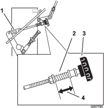
Adjusting the Control Rod
Checking the Control Rod
-
With rear of machine still on jack stands and engine running at full throttle, move the speed-control lever to the medium speed position.
Note: Hold the OPC levers down whenever the speed-control lever is out of the NEUTRAL position or the engine will shut off.
-
Move the respective drive lever upward until it reaches the NEUTRAL position and engage neutral locks.
-
If the tire rotates either direction, adjust the length of the control rod; refer to Adjusting the Control Rod ..
Adjusting the Control Rod
-
Adjust the rod length by releasing the drive lever and removing the hairpin cotter and clevis pin. Rotate the rod in the rod fitting (Figure 39).
-
Lengthen the control rod if the tire is turning in reverse and shorten the rod if the tire is turning forward.
-
Rotate the rod several turns if the tire is rotating fast. Then, adjust the rod in 1/2 turn increments.
-
Place the clevis pin into the drive lever (Figure 39).
-
Release and engage the neutral lock, checking that the tire does not rotate (Figure 40). Continue this process until the tire does not rotate.
-
Install the hairpin cotter between the drive levers and the neutral locks and into the clevis pins (Figure 39).
-
Repeat this adjustment for the opposite side.
Adjusting the Tracking
-
Remove machine from any jack stands.
-
Check the rear tire pressure. Refer to Checking the Tire Pressure.
-
Run the unit and observe the tracking on a level, smooth, hard surface such as concrete or asphalt.
-
If the unit tracks to 1 side or the other, turn the quick track knob. Turn the knob right to steer right and turn the knob left to steer left (Figure 41).
Adjusting the Spring Anchor Links
For medium or heavy duty drive conditions, such as operating with a sulky on steep slopes, a higher spring force may be required on the hydraulic pump control arms to prevent the drive system from stalling.
-
Park the machine on a level surface, disengage the PTO, and engage the parking brake.
-
Shut off the engine, remove the key, and wait for all moving parts to stop before leaving the operating position.
-
For a heavier drive setting, relocate the spring anchor links to either the medium or heavy duty positions (Figure 42). The spring anchor links are attached to the upper rear corner of the hydraulic drive shields on the left and right sides of the machine.
Note: In the medium or heavy duty positions, the drive lever forces at the upper handle will also increase.
Checking the Tire Pressure
| Maintenance Service Interval | Maintenance Procedure |
|---|---|
| Every 50 hours |
|
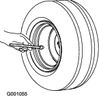
Maintain the air pressure in the rear tires as specified. Check the pressure at the valve stem (Figure 43).
Rear Tire Pressure: 15 psi (1 bar)
Cooling System Maintenance
Cleaning the Air Intake Screen
| Maintenance Service Interval | Maintenance Procedure |
|---|---|
| Before each use or daily |
|
Before each use remove any buildup of grass, dirt or other debris from the cylinder and cylinder head cooling fins, air intake screen on flywheel end, and carburetor-governor levers and linkage. This helps ensure adequate cooling and correct engine speed and reduces the possibility of overheating and mechanical damage to the engine.
Brake Maintenance
Servicing the Brake
Before each use, check the parking brake for proper operation.
Always engage the parking brake when you stop the machine or leave it unattended. If the parking brake does not hold securely, adjust it.
Checking the Parking Brake
| Maintenance Service Interval | Maintenance Procedure |
|---|---|
| Before each use or daily |
|
-
Park the machine on a level surface, disengage the PTO, and engage the parking brake.
-
Shut off the engine, remove the key, and wait for all moving parts to stop before leaving the operating position.
-
Set the parking brake.
Note: Setting the parking brake should take a reasonable amount of force. If it engages too hard or too easily, an adjustment is required. Refer to Adjusting the Parking Brake.
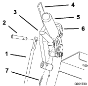
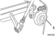
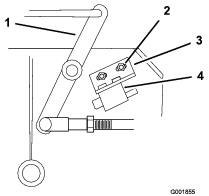
Adjusting the Parking Brake
The parking-brake lever is on the right side of the machine. If the parking brake does not hold securely, adjust it.
-
Check the parking brake before you adjust it; refer to Checking the Parking Brake.
-
Disengage the parking brake; refer to Disengaging the Parking Brake.
-
Remove the spring hairpin from the lower brake link (Figure 44).
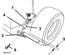
-
Rotate the lower brake link yoke clockwise into the yoke to tighten the parking brake; rotate the brake link yoke counterclockwise out of the yoke out to loosen the parking brake (Figure 44).
Note: With the parking brake in the released position, the clearance between the tire and the flat bar is approximately 6 mm (1/4 inch) (Figure 44).
-
Secure the lower link to the lower brake lever with the hairpin cotter and the clevis pin (Figure 44).
-
Check the brake operation again; refer to Checking the Parking Brake.
Belt Maintenance
Checking the Belts
| Maintenance Service Interval | Maintenance Procedure |
|---|---|
| Every 50 hours |
|
Check the belts for squealing when the belt is rotating, blades slipping when cutting grass, frayed belt edges, burn marks and cracks are signs of a worn mower belt. Replace the mower belt if any of these conditions are evident.
Replacing the Mower Belt
For Rear-Discharge Decks
Note: For the Flail Attachment, refer to the Operator’s Manual for the cutting unit.
-
Park the machine on a level surface, disengage the PTO, and engage the parking brake.
-
Shut off the engine, remove the key, and wait for all moving parts to stop before leaving the operating position.
-
Remove the knobs and the belt cover on the mower deck.
-
Remove the idler pulley and the worn belt (Figure 45).
-
Install the new mower belt.
-
Install the idler pulley.
-
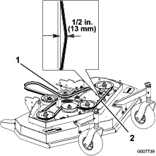
Engage the blade control (PTO) lever and check the belt tension. Refer to Adjusting the Mower Belt Tension.
Note: The proper mower belt tension is 44 to 67 N (10 to 15 lb) with the belt deflected 13 mm (1/2 inch) halfway between the pulleys (Figure 45).
Adjusting the Mower Belt Tension
For Rear-Discharge Decks
Note: For the Flail Attachment, refer to the Operator’s Manual for the cutting unit.
Adjusting the Tension
| Maintenance Service Interval | Maintenance Procedure |
|---|---|
| After the first 8 hours |
|
| After the first 25 hours |
|
| Every 50 hours |
|
Important: When the belt tension or the brake linkage is adjusted, the brake needs adjustment.
Important: The belt must be tight enough to not slip during heavy loads while cutting grass. Overtensioning the belt reduces the spindle bearing life, the belt life and the idler pulley life.
The belt must be tight enough so it does not slip during heavy loads while cutting grass; overtensioning reduces belt and spindle bearing life.
-
Park the machine on a level surface, disengage the PTO, and engage the parking brake.
-
Shut off the engine, remove the key, and wait for all moving parts to stop before leaving the operating position.
-
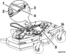
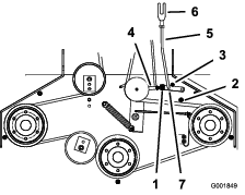
Loosen the locknut on the turnbuckle (Figure 46).
-
Rotate the turnbuckle toward the rear of the mower deck to increase the tension on the belt. Rotate the turnbuckle toward the front of the mower deck to decrease the tension on the belt (Figure 46).
Note: Ensure that the eyebolt threads on both ends of the turnbuckle are engaged a minimum of 8 mm (5/16 inch).
-
Engage the PTO and check the belt tension.
-
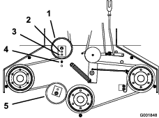
If there is no adjustment left in the turnbuckle and the belt is still loose, position the rear idler pulley in the middle or front hole (Figure 47). Use the hole that gives the correct adjustment.
-
When the idler pulley is moved the belt guide must be moved. Move the belt guide to the front position (Figure 47).
-
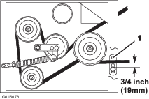
Check the belt guide under the engine frame for proper adjustment (Figure 48).
Note: When the mower belt is engaged, ensure that the distance between the belt guide and the mower belt is 19 mm (3/4 inch) (Figure 48). Adjust the mower belt guide as necessary. The disengaged belt should not drag or fall off the pulley when the guides are properly adjusted.
-
Check the blade brake adjustment; refer to Adjusting the Blade Brake.
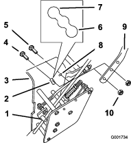
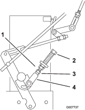
Adjusting the PTO Engagement Linkage
The PTO engagement linkage adjustment is located beneath the front left hand corner of the engine deck.
-
Park the machine on a level surface, disengage the PTO, and engage the parking brake.
-
Shut off the engine, remove the key, and wait for all moving parts to stop before leaving the operating position.
-
Engage the PTO.
-
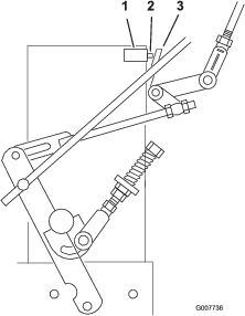
Adjust the linkage length to where the lower end of the bellcrank just clears the axle support gusset (Figure 49).
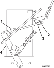
-
Make sure that the assist arm is against the rear assist arm stop on the deck (Figure 50).
-
Push the blade control knob (PTO) down to the DISENGAGED position.
-
The assist arm should contact the front assist arm stop on the deck. If it does not contact, adjust the bellcrank so it is closer to the gusset (Figure 50).
-
To adjust the assist arm link, remove the hairpin cotter from the assist arm (Figure 50).
-
Loosen the nut against the yoke (Figure 49).
-
Remove the assist arm link from the assist arm and rotate the link to adjust the length.
-
Install the assist arm link into the assist arm and secure it with the hairpin cotter (Figure 50).
-
Check if the assist arm hits against the stops correctly.
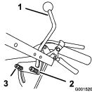
Adjusting the PTO Safety Switch
-
Park the machine on a level surface, disengage the PTO, and engage the parking brake.
-
Shut off the engine, remove the key, and wait for all moving parts to stop before leaving the operating position.
-
Disengage the PTO. Make sure that the assist arm is against the front assist stop arm.
-
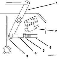
If needed, adjust the blade safety switch by loosening the bolts holding the switch bracket (Figure 51).
-
Move the mounting bracket until the bellcrank presses the plunger by 6 mm (1/4 inch).
Make sure that the bellcrank does not touch the switch body or damage to the switch could occur (Figure 51).
-
Tighten the switch mounting bracket.
Hydraulic System Maintenance
Servicing the Hydraulic System
Warning
Hydraulic fluid escaping under pressure can penetrate skin and cause injury.
-
If hydraulic fluid is injected into the skin it must be surgically removed within a few hours by a doctor familiar with this type of injury. Gangrene may result if this is not done.
-
Keep body and hands away from pin hole leaks or nozzles that eject high-pressure hydraulic fluid.
-
Use cardboard or paper to find hydraulic leaks.
-
Safely relieve all pressure in the hydraulic system before performing any work on the hydraulic system.
-
Make sure that all hydraulic fluid hoses and lines are in good condition and all hydraulic connections and fittings are tight before applying pressure to hydraulic system.
Hydraulic Fluid Specifications
Fluid Type: Mobil 1 15W-50 synthetic motor oil or equivalent synthetic oil.
Important: Use the fluid specified or equivalent. Other fluids could cause system damage.
Hydraulic System Capacity: 2.3 L (77 fl oz)
Checking the Hydraulic Fluid
| Maintenance Service Interval | Maintenance Procedure |
|---|---|
| After the first 8 hours |
|
| Every 25 hours |
|
Note: There are 2 ways of checking the hydraulic fluid: checking the fluid when it is warm and checking the fluid when it is cold. The baffle inside the tank has 2 levels, depending if the fluid is warm or cold.
-
Park the machine on a level surface, disengage the PTO, and engage the parking brake.
-
Shut off the engine, remove the key, and wait for all moving parts to stop before leaving the operating position.
-
Wait for all moving parts to stop before leaving the operating position and then engage the parking brake.
-
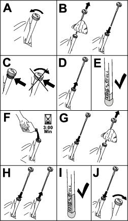
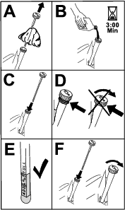
Clean area around cap and filler neck of hydraulic tank (Figure 52).

-
Remove cap from filler neck. Look inside to check if there is fluid in the reservoir (Figure 52).
-
If there is no fluid, add fluid to the reservoir until it reaches the cold level of the baffle.
-
Run the machine at low idle for 15 minutes to allow any air to purge out of the system and warm fluid. Refer to Starting and Stopping the Engine.
-
Check the fluid level while the fluid is warm. If required, add fluid to the reservoir until it reaches the hot level of the baffle.
Note: When the fluid is warm, the fluid level is at the top of the hot level of the baffle (Figure 52).
-
Install cap on filler neck.
Replacing the Hydraulic-Fluid Filter
| Maintenance Service Interval | Maintenance Procedure |
|---|---|
| After the first 8 hours |
|
| Every 200 hours |
|
Important: Do not substitute an automotive oil filter, otherwise severe hydraulic system damage may result.
-
Park the machine on a level surface, disengage the PTO, and engage the parking brake.
-
Shut off the engine, remove the key, and wait for all moving parts to stop before leaving the operating position.
-
Remove hydraulic reservoir cap and temporarily cover the opening with a plastic bag and rubber band to prevent all hydraulic fluid from draining out.
-
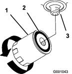
Locate filter under engine base and place drain pan under filter (Figure 53).
-
Remove the old filter and wipe the filter adapter gasket surface clean (Figure 53).
-
Apply a thin coat hydraulic fluid to the rubber gasket on the replacement filter.
-
Install replacement hydraulic filter onto the filter adapter. Do not tighten.
-
Remove plastic bag from reservoir opening and allow filter to fill with hydraulic fluid.
-
When the hydraulic filter is full, turn the oil filter clockwise until the rubber gasket contacts the filter adapter, then tighten the filter an additional 1/2 turn (Figure 53).
-
Clean up any spilled fluid.
-
If there is no fluid, hydraulic fluid to approximately 6 mm (1/4 inch) below the top of reservoir baffle.
Important: Use the oil specified in Hydraulic Fluid Specifications or equivalent. Other fluids could cause system damage.
-
Start engine and let run for about 2 minutes to purge air from the system. Shut off the engine and check for leaks. If 1 or both wheels do not drive, refer to Bleeding the Hydraulic System.
-
Check level and add fluid, if required. Do not overfill.
Bleeding the Hydraulic System
The traction system is self bleeding, however, it may be necessary to bleed the system if fluid is changed or after work is performed on the system.
Purge the air from the hydraulic system when any hydraulic components, including oil filter, are removed or any of the hydraulic lines are disconnected. The critical area for purging air from the hydraulic system is between the oil reservoir and each charge pump located on the top of each variable displacement pump. Air in other parts of the hydraulic system will be purged through normal operation once the charge pump is primed.
-
Park the machine on a level surface, disengage the PTO, and engage the parking brake.
-
Shut off the engine, remove the key, and wait for all moving parts to stop before leaving the operating position.
-
Raise the rear of the machine up onto jack stands high enough to raise the drive wheels off the ground.
-
Check the hydraulic-fluid level.
-
Start the engine and move the throttle control to the full throttle position. Move the speed-control lever to the middle speed position and place the drive levers into the drive position.
If either drive wheel does not rotate, it is possible to assist the purging of the charge pump by carefully rotating the tire in the forward direction.
Note: It is necessary to lightly touch the charge pump cap with your hand to check the pump temperature. If the cap is too hot to touch, turn off engine. The pumps may be damaged if the pump becomes too hot. If either drive wheel still does not rotate, continue to the next step.
-
Thoroughly clean the area around each of the charge pump housings.
-
To prime the charge pump, continue as follows:
-
Shut off the engine and remove the key.
-
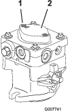
Loosen the 2 hex-socket head capscrews (Figure 54) 1-1/2 turns only.
-
Lift the charge pump housing upward and wait for a steady flow of fluid to flow out from under the housing. Tighten the capscrews.
-
Repeat this for both pumps.
Note: The hydraulic reservoir can be pressurized to up to 5 psi (0.35 bar) to speed up this process.
-
-
If either drive wheel still does not rotate, stop and repeat steps 4 and 5 on the respective pump. If wheels rotate slowly, the system may prime after additional running. Check the hydraulic-fluid level.
-
Allow unit to run several minutes after the charge pumps are primed with drive system in the full speed position.
-
Check the hydraulic control linkage adjustment. Refer to Adjusting the Hydraulic Control Linkages.
Checking the Hydraulic Lines
| Maintenance Service Interval | Maintenance Procedure |
|---|---|
| Every 100 hours |
|
Check the hydraulic lines and hoses for leaks, loose fittings, kinked lines, loose mounting supports, wear, weather and chemical deterioration. Make necessary repairs before operating.
Note: Keep areas around hydraulic system clean from grass and debris buildup.
Warning
Hydraulic fluid escaping under pressure can penetrate skin and cause injury.
-
If hydraulic fluid is injected into the skin it must be surgically removed within a few hours by a doctor familiar with this type of injury. Gangrene may result if this is not done.
-
Keep body and hands away from pin hole leaks or nozzles that eject high-pressure hydraulic fluid.
-
Use cardboard or paper to find hydraulic leaks.
-
Safely relieve all pressure in the hydraulic system before performing any work on the hydraulic system.
-
Make sure that all hydraulic fluid hoses and lines are in good condition and all hydraulic connections and fittings are tight before applying pressure to hydraulic system.
Mower Deck Maintenance
Servicing the Cutting Blades
For Rear-Discharge Decks
Note: For the Flail Attachment, refer to the Operator’s Manual for the cutting unit.
To ensure a superior quality of cut, keep the blades sharp. For convenient sharpening and replacement, keep extra blades on hand.
Warning
A worn or damaged blade can break, and a piece of the blade could be thrown at you or bystanders, resulting in serious personal injury or death.
-
Inspect the blade periodically for wear or damage.
-
Replace a worn or damaged blade.
Before Inspecting or Servicing the Blades
-
Park the machine on a level surface, disengage the PTO, and engage the parking brake.
-
Shut off the engine, remove the key, and disconnect the spark-plug wires from the spark plugs.
Inspecting the Blades
| Maintenance Service Interval | Maintenance Procedure |
|---|---|
| Before each use or daily |
|
-
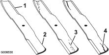
Inspect the cutting edges (Figure 55).
-
If the edges are not sharp or have nicks, remove and sharpen the blade; refer to Sharpening the Blades.
-
Inspect the blades, especially in the curved area.
-
If you notice any cracks, wear, or a slot forming in this area, immediately install a new blade (Figure 55).
Checking for Bent Blades
-
Rotate the blades until the ends face forward and backward.
-
Measure from a level surface to the cutting edge, position A, of the blades (Figure 56).
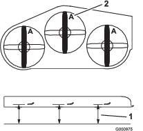
-
Rotate the opposite ends of the blades forward.
-
Measure from a level surface to the cutting edge of the blades at the same position as in step 2 above.
Note: The difference between the dimensions obtained in steps 2 and 4 must not exceed 3 mm (1/8 inch).
Note: If this dimension exceeds 3 mm (1/8 inch), the blade is bent and must be replaced.
Removing the Blades
Replace the blades if you hit a solid object or if the blades are out of balance or bent. To ensure optimum performance and continued safety conformance of the machine, use genuine Toro replacement blades. Replacement blades made by other manufacturers may result in non-conformance with safety standards.
-
Hold the blade bolt with a wrench.
-
Remove the nut, blade bolt, curved washer, blade, spacers, and thin washer from the spindle (Figure 57).
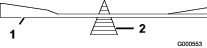
Sharpening the Blades
-
Use a file to sharpen the cutting edge at both ends of the blade (Figure 58).
Note: Maintain the original angle.
Note: The blade retains its balance if the same amount of material is removed from both cutting edges.

-
Check the balance of the blade by putting it on a blade balancer (Figure 59).
Note: If the blade stays in a horizontal position, the blade is balanced and can be used.
Note: If the blade is not balanced, file some metal off the end of the sail area only (Figure 58).
-
Repeat this procedure until the blade is balanced.
Installing the Blades
-
Install the bolt, curved washer, and blade. Select the proper number of spacer(s) for the height of cut, and slide the bolt into the spindle (Figure 57).
Important: The curved part of the blade must point upward toward the inside of the mower deck to ensure proper cutting.
-
Install the remaining spacer(s) and secure them with a thin washer and a nut (Figure 57).
-
Torque the blade bolt to 75 to 80 N∙m (101 to 108 ft-lb).
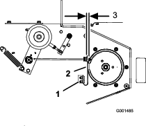
Adjusting the Blade Brake
-
Park the machine on a level surface, disengage the PTO, and engage the parking brake.
-
Shut off the engine, remove the key, and wait for all moving parts to stop before leaving the operating position.
-
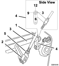
If necessary, adjust the spring mounting bolts so that the blade brake pad rubs against both sides of the pulley groove (Figure 60).
-
Adjust the nut at the end of the blade brake rod until there is 3 to 5 mm (1/8 to 3/16 inch) between the nut and spacer (Figure 60).
-
Engage the blades. Ensure that the blade brake pad no longer contacts the pulley groove.
Storage
-
Park the machine on a level surface, disengage the PTO, and engage the parking brake.
-
Shut off the engine, remove the key, and wait for all moving parts to stop before leaving the operating position.
-
Remove grass clippings, dirt, and grime from the external parts of the entire machine, especially the engine. Clean dirt and chaff from the outside of the engine's cylinder head fins and blower housing.
Important: You can wash the machine with mild detergent and water. Do not pressure wash the machine. Avoid excessive use of water, especially near the shift lever plate, and engine.
-
Check the brake; refer to Servicing the Brake.
-
Service the air cleaner; refer to Servicing the Air Cleaner.
-
Grease the machine; refer to Lubrication.
-
Change the crankcase oil; refer to Changing the Engine Oil.
-
Check the tire pressure; refer to Checking the Tire Pressure.
-
For long-term storage:
-
Add fuel stabilizer/conditioner to fresh fuel in the tank. Follow the mixing instructions from the stabilizer manufacturer. Do not use an alcohol-based stabilizer (ethanol or methanol).
-
Run the engine to distribute conditioned fuel through the fuel system for 5 minutes.
-
Shut off the engine, allow it to cool, and drain the fuel tank; refer to Servicing the Fuel Tank, or operate engine until it shuts off.
-
Start the engine and run until it shuts off. Repeat, with the choke engaged, until the engine does not start.
-
Dispose of fuel properly. Recycle it as per local codes.
Important: Do not store fuel containing stabilizer/conditioner longer than the duration recommended by the fuel-stabilizer manufacturer.
-
-
Remove the spark plug(s) and check its condition; refer to Servicing the Spark Plug. With the spark plug(s) removed from the engine, pour 2 tablespoons of engine oil into the spark plug hole. Now use the starter to crank the engine and distribute the oil inside the cylinder. Install the spark plug(s). Do not install the spark plug wires onto the spark plug(s).
-
Check and tighten all bolts, nuts, and screws. Repair or replace any part that is damaged or worn.
-
Paint all scratched or bare metal surfaces. Paint is available from your Authorized Service Dealer.
-
Store the machine in a clean, dry garage or storage area. Remove the key from the switch and keep it in a memorable place. Cover the machine to protect it and keep it clean.
Troubleshooting
| Problem | Possible Cause | Corrective Action |
|---|---|---|
| The engine does not start, starts hard, or fails to keep running. |
|
|
| The engine loses power. |
|
|
| The engine overheats. |
|
|
| The machine does not drive. |
|
|
| The machine is vibrating abnormally. |
|
|
| The cutting height is uneven. |
|
|
| The blades do not rotate. |
|
|
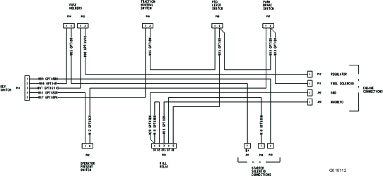
Schematics
Electrical Schematic
Hydraulic Schematic