
 , which means Caution, Warning,
or Danger—personal safety instruction. Failure to comply with
these instructions may result in personal injury or death.
, which means Caution, Warning,
or Danger—personal safety instruction. Failure to comply with
these instructions may result in personal injury or death.


Maintenance
Maintenance Safety
-
Before servicing or adjusting the machine, stop the machine, shut off the engine, engage the parking brake, remove the key, and wait for all moving parts to stop.
-
Perform only those maintenance instructions described in this manual. If major repairs are ever needed or assistance is desired, contact an authorized Toro distributor.
-
Ensure that the machine is in safe operating condition by keeping nuts, bolts, and screws tight.
-
If possible, do not perform maintenance while the engine is running. Keep away from moving parts.
-
Do not check or adjust the chain tension when the tow vehicle engine is running.
-
Carefully release pressure from components with stored energy.
-
Support the machine with blocks or jack stands when working beneath it.
-
After maintaining or adjusting the machine, ensure that all guards are installed.
Recommended Maintenance Schedule(s)
| Maintenance Service Interval | Maintenance Procedure |
|---|---|
| After the first hour |
|
| After the first 10 hours |
|
| Before each use or daily |
|
| Every 40 hours |
|
| Every 200 hours |
|
Pre-Maintenance Procedures
Preparing for Maintenance
-
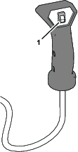
Shut off the hand-control switch for the topdresser.
-
Move the machine to a level surface.
-
Set the parking brake of the traction unit, shut off the engine, remove the key, and wait for all moving parts to stop before leaving the operator’s seat.
Raising the Machine
-
Empty the hopper.
-
Perform the steps in Preparing for Maintenance.
-
Use the skids as the jacking points.
-
Support the machine with jack stands.
-
When working on the wheels, pivot them up or down to expose wheel bolts.
Important: If you remove the wheels and installed them, torque wheel bolts as specified in Torqueing the Wheel Bolts. Incorrect bolt torque could result in failure or loss of the wheel.
Lubrication
Grease Specification
No. 2 Lithium based grease
Greasing the Bearings and Bushings
| Maintenance Service Interval | Maintenance Procedure |
|---|---|
| Every 200 hours |
|
-
Perform the steps in Preparing for Maintenance.
-
Lubricant each of the grease fitting described in the grease-fitting table with the specified grease.
| Location | Quantity |
|---|---|
| Roller shaft bearing (Figure 14) | 4 |
| Brush shaft bearing (Figure 14) | 1 |
| Pivot bearing (Figure 15 | 4 |
| Wheel bearing (Figure 15) | 4 |
Important: Lubricate the bearings to maintain a slight leakage between bearings and housings. Too much grease can cause overheating or damage to seals.
Note: We do not recommend lubricating the drive chains unless they become stiff from rust. If the chain rusts, lightly lubricate it with a dry-type lubricant. This reduces the likelihood of sand build-up or other top-dressing material adhering to the chain.
Drive System Maintenance
Checking the Tire Air Pressure
| Maintenance Service Interval | Maintenance Procedure |
|---|---|
| Before each use or daily |
|
-
Perform the steps in Preparing for Maintenance.
-
Check the tire air pressure.
You should measure 138 to 207 kPa (20 to 30 psi) air pressure.
-
If the tire air pressure is too low or too high, add air to or remove air from the tires until you measure 138 to 207 kPa (20 to 30 psi).
Torqueing the Wheel Bolts
| Maintenance Service Interval | Maintenance Procedure |
|---|---|
| After the first hour |
|
| After the first 10 hours |
|
| Every 200 hours |
|
Important: Failure to maintain proper torque could result in failure or loss of wheel.
-
Perform the steps in Preparing for Maintenance.
-
Torque 20 wheel bolts to 109 to 122 N∙m(80-90 ft-lb).
Tensioning the Wheel-Drive Chain
-
Perform the steps in Preparing for Maintenance.
-
Loosen carriage bolts and nuts that secure the hydraulic motor/pump to axle cradle (Figure 16).
-
Rotate motor sprocket assembly (Figure 16) until the wheel-drive chain deflects 3.2 mm (1/8 inch).
Note: Access to chain is through cutout in lower side of axle cradle.
Important: Do not over tension the chain or it will wear prematurely. Do not under-tension the chain or it will cause sprocket wear.
-
Tighten mounting bolts.
Note: We do not recommend lubricating the drive chains unless they become stiff from rust. If the chain rusts, lightly lubricate it with a dry-type lubricant. This reduces the likelihood of sand build-up or other top-dressing material adhering to the chain.
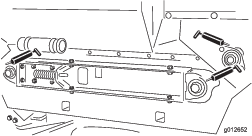
Tensioning the Conveyor-Belt Chain
-
Perform the steps in Preparing for Maintenance.
-
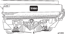
Remove the chain cover (Figure 17).
-
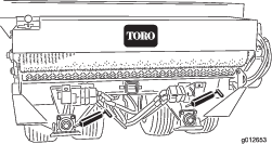
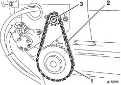
Loosen bolts and nuts that secure the motor and sprocket assembly to the main frame (Figure 18).
-
Rotate motor and sprocket assembly (Figure 18) in mounting slots until the conveyer-belt chain deflects 3.2 mm (1/8 inch).
Important: Do not over tension the chain or it will wear prematurely. Do not under-tension the chain or it will cause sprocket wear.
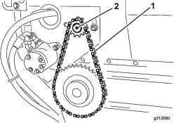
-
Tighten mounting bolts (Figure 18).
-
Install chain cover (Figure 17).
Belt Maintenance
Tensioning the Conveyor Belt
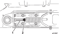
When conveyor belt is adjusted properly, the compressed length of each compression spring should be 4-7/16 inches (112 mm). Adjust conveyor belt as follows:
-
Empty the hopper.
-
Perform the steps in Preparing for Maintenance.
-
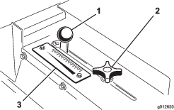
Loosen rear jam nut (Figure 19).
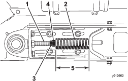
-
Adjust forward jam nut to compression spring to 4-7/16 inches (112 mm).
-
Tighten jam rear nut.
-
Repeat steps 3 through 5 at the other side of the machine
-
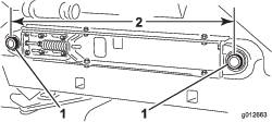
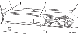
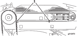
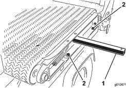
Measure the distance between center points of the belt-roller shafts at each side of machine to ensure that the measurements are equal (Figure 20).
Equal distance measures approximately 895 mm (35-1/4 inches).
Replacing the Conveyor Belt
Preparing to Machine
-
Empty the hopper.
-
Perform the steps in Preparing for Maintenance.
-
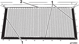
Inspect hopper seals and gate edge for wear or torn edges (Figure 21).
Replace worn or damaged components to ensure proper operation of new conveyor belt.
Removing the Conveyer Chain
Disassembling the Slider Bed
-
Loosen forward and rear jam nuts on tension rod to release spring tension (Figure 24).
-
At each side of machine, remove 2 capscrews, 2 washers, and 2 locknuts that secure the hopper to slider-frame rails (Figure 25).
-
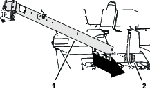
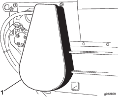
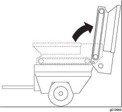
Pivot hopper rearward and lean it against wall, post, ladder, etc. (Figure 26)
Important: Do not allow hopper to rest against the rear of machine to avoid damaging the brush or the hydraulic couplers.Make sure that the hopper is pivoted beyond center and/or secured to wall or post to prevent it from accidentally falling on work area (Figure 26).
-
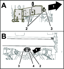
At the right side of machine, loosen 2 capscrews that secure slider-frame rail to the right fender (Figure 27). Ensure that the capscrews are loose enough to allow slider bed tip.
-
At the left side of machine, remove 2 capscrews and 2 washers that secure slider-frame rail to the left fender (Figure 28).
Removing the Belt
Cut belt and remove it from rollers.
Installing the Belt
-
Insert a lift bar though the hole left slider-frame rail and raise lift bar to tip frame rail slightly; refer to Figure 28 in Disassembling the Slider Bed.
-
Assemble the belt over the lift bar and rollers as far as possible.
-
Insert a plastic belt tool between each roller and the belt.
Rotate rollers until each tool is positioned to the outside of each roller. Insert the tool past rib in the center of belt.
-
Slide belt and belt tools further onto rollers until belt is centered on rollers.
-
Remove belt tools.
-
Align belt so that the belt rib fits into alignment grooves in each roller.
Assembling the Slider Bed
-
At the left side of machine, assemble the slider-frame rail to the left fender (Figure 29) with the 2 capscrews and 2 washers that you removed in Disassembling the Slider Bed, and tighten the capscrews.
-
At the right side of machine, tighten 2 capscrews that secure slider-frame rail to the right fender (Figure 30).
-
Carefully rotate the hopper down onto the slider-frame rails; refer to Figure 26 of Disassembling the Slider Bed
-
At each side of machine, secure the hopper to slider-frame rails (Figure 31) with the 2 capscrews, 2 washers, and 2 locknuts that you removed in Disassembling the Slider Bed.
-
Tension the conveyer belt; refer to Tensioning the Conveyor Belt
Installing the Conveyer Chain
-
Assemble the chain onto the small sprocket and secure the chain with the master link (Figure 32).
-
If you loosen the motor-mount bolts, tension the conveyer-belt chain, refer to Tensioning the Conveyor-Belt Chain
-
Install the chain cover (Figure 33).
Hydraulic System Maintenance
Hydraulic System Safety
-
Seek immediate medical attention if fluid is injected into skin. Injected fluid must be surgically removed within a few hours by a doctor.
-
Ensure that all hydraulic-fluid hoses and lines are in good condition and all hydraulic connections and fittings are tight before applying pressure to the hydraulic system.
-
Keep your body and hands away from pinhole leaks or nozzles that eject high-pressure hydraulic fluid.
-
Use cardboard or paper to find hydraulic leaks.
-
Safely relieve all pressure in the hydraulic system before performing any work on the hydraulic system.
Hydraulic Fluid Specification
The recommended replacement fluid is:
Toro Premium All Season Hydraulic Fluid: Available in 19 L (5 US gallon) containers or 208 L (55 US gallon) drums—see the Parts Catalog or your Toro distributor for part numbers.
Alternative fluids: If the Toro fluid is not available, other fluids may be used provided that they meet all of the following material properties and industry specifications. Check with your oil supplier to identify a satisfactory product.
Note: Toro does not assume responsibility for damage caused by improper substitutions, so use only products from reputable manufacturers who stand behind their recommendation.
| High Viscosity Index/Low Pour Point Antiwear Hydraulic Fluid, ISO VG 46 Multigrade | |||
| Material Properties: | |||
| Viscosity, ASTM D445 | cSt @ 40°C (104°F) 44 to 48cSt @ 100°C (212°F) 7.9 to 9.1 | ||
| Viscosity index, ASTM D2270 | 140 or higher (high viscosity index indicates a multiweight fluid) | ||
| Pour point, ASTM D97 | -36.7°C to -45°C (-34°F to -49°F) | ||
| FZG, fail stage | 11 or better | ||
| Water content (new fluid) | 500 ppm (maximum) | ||
| Industry Specifications: | |||
| Vickers I-286-S, Vickers M-2950-S, Denison HF-0, Vickers 35 VQ 25 (Eaton ATS373-C) | |||
The proper hydraulic fluids must be specified for mobile machinery (as opposed to industrial plant usage), multiweight-type, with ZnDTP or ZDDP antiwear additive package (not an ashless-type fluid).
Important: Many hydraulic fluids are almost colorless, making it difficult to spot leaks. A red dye additive for the hydraulic system oil is available in 20 ml (2/3 fl oz) bottles. One bottle is sufficient for 15 to 22 L (4 to 6 US gallons) of hydraulic fluid. Order part 44-2500 from your authorized Toro distributor.
Synthetic, Biodegradable Hydraulic Fluid: Available in 19 L (5 US gallon) containers or 208 L (55 US gallon) drums—see the Parts Catalog or your Toro distributor for part numbers.
This high-quality, synthetic, biodegradable fluid has been tested and found compatible for this Toro model. Other brands of synthetic fluid may have seal compatibility problems and Toro cannot assume responsibility for unauthorized substitutions.
Note: This synthetic fluid is not compatible with the Toro Biodegradable Fluid previously sold. See your Toro Distributor for more information.
Alternative fluids:
-
Mobil EAL Envirosyn H 46 (US)
-
Mobil EAL Hydraulic Oil 46 (international)
Checking the Hydraulic Fluid Level
| Maintenance Service Interval | Maintenance Procedure |
|---|---|
| Before each use or daily |
|
-
Perform the steps in Preparing for Maintenance
-
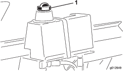
Clean area around filler neck and cap of hydraulic tank, and remove the cap (Figure 34).
-
Check fluid level. Fluid level should be 1/2 way up the screen in filler neck.
-
If level is low, add the specified fluid to raise level.
Changing the Hydraulic Fluid
| Maintenance Service Interval | Maintenance Procedure |
|---|---|
| Every 200 hours |
|
Reservoir fluid capacity: approximately 9.5 L (2.5 US gallon)
-
Perform the steps in Preparing for Maintenance.
-
Align a drain pan with a 9.5 L (2.5 US gallon) capacity under the hydraulic reservoir.
-
Remove the fitting from bottom of hydraulic reservoir and allow the reservoir to drain completely (Figure 35).
-
Install and tighten hydraulic-reservoir fitting.
-
Clean area around filler neck and cap of hydraulic tank, and remove the cap (Figure 35).
-
Add approximately 9.5 L (2.5 US gallon) of the specified hydraulic fluid; refer to Hydraulic Fluid Specification.
Important: Use only hydraulic fluids specified. Other fluids could cause damage to components of the hydraulic system.
-
Check level of fluid and add enough to the fluid level stated in Checking the Hydraulic Fluid Level.
Important: Do not overfill the reservoir with hydraulic fluid.
-
Install reservoir cap (Figure 35).
Replacing the Hydraulic Filter
| Maintenance Service Interval | Maintenance Procedure |
|---|---|
| Every 200 hours |
|
-
Perform the steps in Preparing for Maintenance.
-
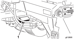
Clean area around filter and hydraulic manifold, align a drain pan under filter, and remove filter (Figure 36).
-
Lubricate the gasket of the new filter with the specified hydraulic fluid; refer to Hydraulic Fluid Specification.
-
Clean the filter-mounting area of the hydraulic manifold.
-
Thread the filter onto the mount until gasket manifold, then tighten filter one-half turn.
-
Tow machine to power the hydraulic system and check for hydraulic leaks.
Checking the Hydraulic Lines and Hoses
| Maintenance Service Interval | Maintenance Procedure |
|---|---|
| Before each use or daily |
|
Inspect hydraulic lines and hoses daily for leaks, kinked lines, loose mounting supports, wear, loose fittings, weather deterioration and chemical deterioration. Make all necessary repairs before operating the machine.
Brush Maintenance
Checking the Brush for Position and Wear
| Maintenance Service Interval | Maintenance Procedure |
|---|---|
| Every 40 hours |
|
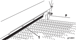
Brush must make enough contact with conveyor belt to disperse top-dressing material but not restrict the rotation of the brush. A piece of stiff paper can be inserted between the conveyor belt and the brush to check the adjustment. .
-
Insert a piece of stiff between the conveyor belt and the brush to check the adjustment.
-
Check that the brush is same height from side to side.
-
Check the condition of the brush bristles.
If the bristles are excessively worn replace the brush. If the bristles are worn uneven either replace the brush or adjust the brush position; refer to Adjusting the Brush Position.
Adjusting the Brush Position
Note: If you are using moist top-dressing material, you may need to adjust the brush position so that the bristles will whisk material from between conveyor belt lugs without excessively contacting smooth portion of belt.
-
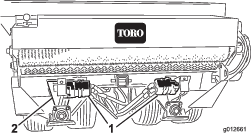
Loosen nuts that secure the bearing housing (Figure 37) to right side of machine.
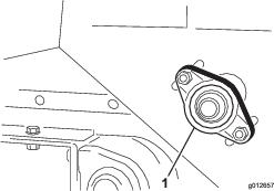
-
Loosen nuts that secure the brush motor (Figure 38) to left side of machine.
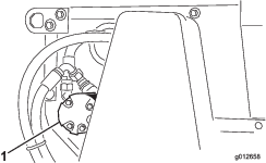
-
Slide brush into position at right side, and snug the nuts.
-
Slide brush into position at left side, and snug the nuts.
-
Insert a piece of stiff paper between the brush and the conveyor belt.
The brush must be the same height from side to side.
-
If the brush position is correct, tighten nuts.
If the brush position is not correct, repeat steps 1 through 6.
Cleaning
Thoroughly clean the machine, especially inside the hopper. Clean the hopper and conveyor belt area free of any sand particles.