Setup
Preparing the Machine
Caution
If you leave the key in the ignition switch, someone could accidently start the engine and seriously injure you or bystanders.
Remove the key from the ignition switch before you do any maintenance.
-
Park the machine on a level surface.
-
Engage the parking brake.
-
Lower the cutting units.
-
Shut off the engine and remove the key.
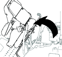
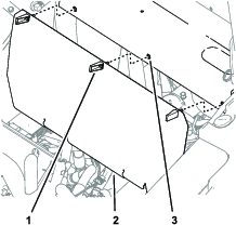
Accessing the Machine
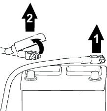
Disconnecting the Battery Cables
Warning
Battery terminals or metal tools could short against metal components, causing sparks.
-
When removing or installing the battery, do not allow the battery terminals to touch any metal parts of the machine.
-
Do not allow metal tools to short between the battery terminals and metal parts of the machine.
-
Always keep the battery strap in place to protect and secure the battery.
Warning
Electrical sparks can cause the battery gasses to explode, resulting in personal injury.
Incorrect battery cable routing could damage the machine and cables, causing sparks.
-
Always disconnect the negative (black) battery cable before disconnecting the positive (red) cable.
-
Always connect the positive (red) battery cable before connecting the negative (black) cable.
Preparing the Power Harness
Parts needed for this procedure:
| Power harness | 1 |
| Fuse (10 A) | 1 |
| Maxifuse (60 A) | 1 |
| Solenoid | 1 |
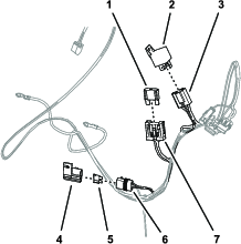
Routing and Connecting the Power Harness
-
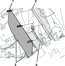
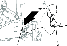
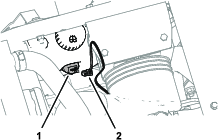
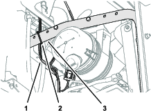
At the left side of the machine, route the power harness branch with the tab-terminal connector toward the front of the engine and the lower roll-bar tube (Figure 7).
-
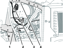
Route the power harness branch with the tab-terminal connector along the cross channel and toward the access panel for the control panel cover (Figure 8).
-
Route the power harness branch with the 2-pin connector, single-pin connector, and 8-socket connector along the lower roll-bar tube and upward toward the support tube (Figure 7).
-
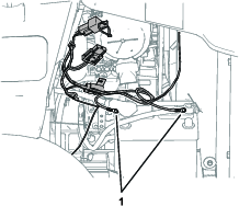
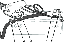
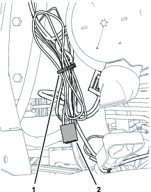
Route the 2 ring terminals toward the clamps of the battery cables (Figure 9).
-
Route the power harness branch with a black wire, blue wire, and 2-socket connector to the pump of the washer-fluid tank (Figure 10 or Figure 11).
Connecting the Power Harness to the Machine
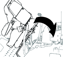
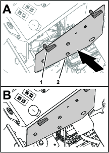
Removing the Control Panel Cover
Connecting the Power Harness Wire
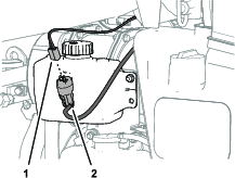
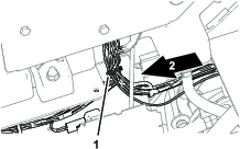
Connect the power harness branch with the tab-terminal connector (green wire) into the insulated single-socket connector of the machine wire harness (pink wire—from the fuse block) as shown in Figure 13.
Installing the Control Panel Cover
Assembling the Ring Terminals to the Battery Cables
-
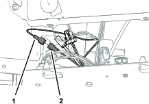
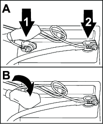
At the positive and negative battery cables, remove the battery-clamp nuts from the short side of the battery clamp bolts (Figure 15).
-
Assemble the ring terminal of the power harness with the black wire onto the battery clamp bolt for the negative battery cable with a battery-clamp nut (Figure 15).
-
Assemble the ring terminal of the power harness with the red wire onto the battery clamp bolt for the positive battery cable with a battery-clamp nut (Figure 15).
Note: Do not assemble the battery cables to the machine. You will connect the battery in a later step.
Connecting the Power Harness to the Optional Sunshade Harness
Connect the 2-pin connector of the sunshade harness into the 2-socket connector of the power harness (Figure 16).

Connecting the Power Harness to the Optional Polar Trac Cab Components
-
Connect the power harness to the pump for the washer-fluid tank and secure the power harness branch to the machine; refer to the Operator’s Manual for the Polar Trac Cab.
-
Connect the power harness to the cab wire harness; refer to the Operator’s Manual for the Polar Trac Cab.
Securing the Power Harness
Parts needed for this procedure:
| Cable tie | 6 |
Securing the Harness
-
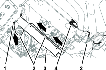
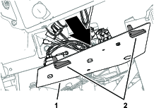
At the control panel cover, secure the power harness to the wire harness of the machine with a cable tie as shown in Figure 17.
-
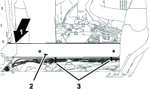
Below the cross channel, secure the power harness to the wire harness of the machine with 2 cable ties as shown in Figure 18.
-
Above the engine, secure the power harness to the radiator support tube as shown in Figure 19.
Connecting the Battery
Warning
Electrical sparks can cause the battery gasses to explode, resulting in personal injury.
Incorrect battery cable routing could damage the machine and cables, causing sparks.
-
Always disconnect the negative (black) battery cable before disconnecting the positive (red) cable.
-
Always connect the positive (red) battery cable before connecting the negative (black) cable.
-
Assemble the negative battery cable onto the negative battery post (Figure 21).
-
Tighten the battery-clamp nut to 20 to 25 N∙m (175 to 225 in-lb).
-
Assemble the positive battery cable onto the positive battery post (Figure 21).
-
Tighten the battery-clamp nut to 20 to 25 N∙m (175 to 225 in-lb).
-
Assemble the insulator over the positive battery post (Figure 21).