Introduction

CONGRATULATIONS on the purchase of your Exmark UltraVac. This product has been carefully designed and manufactured to give you a maximum amount of dependability and years of trouble-free operation.

This manual contains operating, maintenance, adjustment, and safety instructions for your Exmark UltraVac.

BEFORE OPERATING YOUR MOWER, CAREFULLY READ THIS MANUAL IN ITS ENTIRETY.

By following the operating, maintenance, and safety instructions, you will prolong the life of your UltraVac, maintain its maximum efficiency, and promote safe operation.

Important: To maximize safety, performance, and proper operation of this machine, it is essential that all operators carefully read and fully understand the contents of the Operator’s manual provided with the product. Safe operation of Exmark equipment is essential. Failure to comply with the operating instructions or receive proper training may result in injury. Go to https://www.Exmark.com for additional safe operation information, such as safety tips, training materials, and Operator’s manuals.

All Exmark equipment dealers and distributors are kept informed of the latest methods of servicing and are equipped to provide prompt and efficient service in the field or at their service stations. They carry ample stock of service parts or can secure them promptly for you from the factory.

All Exmark parts are thoroughly tested and inspected before leaving the factory, however, attention is required on your part if you are to obtain the fullest measure of satisfaction and performance.

Whenever you need service, genuine Exmark parts, or additional information, contact an Authorized Service Dealer or Exmark Customer Service and have the model and serial numbers of your product ready.

Figure 1 and Figure 2 identify the location of the model and serial numbers on the product. Write the numbers in the space provided.

g031991
g032034

For complete warranty details, see https://www.Exmark.com. You may also call us 402-223-6375 to request a written copy of the product’s warranty.

Warning

CALIFORNIA

Proposition 65 Warning

Use of this product may cause exposure to chemicals known to the State of California to cause cancer, birth defects, or other reproductive harm.

Exmark reserves the right to make changes or add improvements to its products at any time without incurring any obligation to make such changes to products manufactured previously. Exmark, or its distributors and dealers, accept no responsibility for variations which may be evident in the actual specifications of its products and the statements and descriptions contained in this publication.

Exmark Parts Plus EN

Safety

Safety Alert Symbol

This Safety Alert Symbol (Figure 3) is used both in this manual and on the machine to identify important safety messages which must be followed to avoid accidents.

This symbol means: ATTENTION! BECOME ALERT! YOUR SAFETY IS INVOLVED!

g000502

The safety alert symbol appears above information which alerts you to unsafe actions or situations and will be followed by the word DANGER, WARNING, or CAUTION.

DANGER: Indicates an imminently hazardous situation which, if not avoided, Will result in death or serious injury.

WARNING: Indicates a potentially hazardous situation which, if not avoided, Could result in death or serious injury.

CAUTION: Indicates a potentially hazardous situation which, if not avoided, May result in minor or moderate injury.

This manual uses two other words to highlight information. Important calls attention to special mechanical information and Note emphasizes general information worthy of special attention.

General Safety Information

This machine is capable of amputating hands and feet and of throwing objects. Exmark designed and tested this machine to offer reasonably safe service; however, failure to comply with safety instructions may result in injury or death.

  • Read, understand, and follow all instructions and warnings in the mower and UltraVac Operator’s Manuals and other training material, on the machine, engine, and attachments. All operators and mechanics should be trained. If the operator(s) or mechanic(s) can not read this manual, it is the owner’s responsibility to explain this material to them; other languages may be available on our website.

  • Only allow trained, responsible, and physically capable operators that are familiar with the safe operation, operator controls, and safety signs and instructions to operate the machine. Never let children or untrained people operate or service the equipment. Local regulations may restrict the age of the operator.

  • Do Not put your hands or feet near moving components of the machine.

  • Never operate the machine with damaged guards, shields, or covers. Always have safety shields, guards, switches and other devices in place and in proper working condition.

  • Stop the machine, shut off the engine, and remove the key before servicing, fueling, or unclogging the machine.

Safety and Instructional Decals

  • Keep all safety signs legible. Remove all grease, dirt and debris from safety signs and instructional labels.

  • Replace all worn, damaged, or missing safety signs.

  • When replacement components are installed, be sure that current safety signs are affixed to the replaced components.

  • If an attachment or accessory has been installed, make sure current safety signs are visible.

  • New safety signs may be obtained from your authorized Exmark equipment dealer or distributor or from Exmark Mfg. Co. Inc.

  • Safety signs may be affixed by peeling off the backing to expose the adhesive surface. Apply only to a clean, dry surface. Smooth to remove any air bubbles.

  • Familiarize yourself with the following safety signs and instruction labels. They are critical to the safe operation of your Exmark commercial mower.

 
decal106-5517
decal112-9028
decal126-4659
decal126-4661
decal126-4662
decal126-4853
decal133-8061
decal126-4584

Specifications

Systems

Bagging System

  • Collection Hopper:

    • Steel and Polyethylene hopper. Commercial grade, cloth mesh door with reinforced bottom.

    • Capacity:

      • Models ending with “7”: 7.0 bushels

      • Models ending with “11”: 11.0 bushels

  • Dump Mechanism: Manual dump from seat

  • Blower Tube: Fixed, abrasion resistant molded polyethylene.

  • Impeller: 5–bladed, 1/4 inch (6.4 mm) thick abrasion resistant steel, with vertical axis.

  • Impeller bearings: 1 inch (2.5 cm) sealed non-greaseable bearings.

Dimensions

Overall Width:

7-Bushel

 w/UltraVac
Lazer Z w/48 inch Deck62.50 inches (158.8 cm)
Lazer Z w/52 inch Deck67.75 inches (172.1 cm)

11-Bushel

 w/UltraVac
Lazer Z w/60 inch Deck75.00 inches (190.5 cm)
Lazer Z w/72 inch Deck87.25 inches (221.6 cm)

Overall Length:

7-Bushel

w/UltraVac
Lazer Z w/48 inch Deck102.00 inches (259.1 cm)
Lazer Z w/52 inch Deck102.00 inches (259.1 cm)

11-Bushel

w/UltraVac
Lazer Z w/60 inch Deck106.50 inches (270.5 cm)
Lazer Z w/72 inch Deck109.50 inches (278.1 cm)

Curb Weight:

7-Bushel

  UltraVac Weight
For units w/48 inch Deck (3 toe board weights)331 lb (150 kg)
For units w/52 inch Deck (2 toe board weights)288 lb (130 kg)

11-Bushel

  UltraVac Weight
For units w/60 inch Deck (2 toe board weights)477 lb (216 kg)
For units w/72 inch Deck (1 toe board weights)434 lb (197 kg)

Torque Requirements

Bolt LocationTorque
Impeller Spindle Bottom Nut55-60 ft-lb (75-81 N-m)
Impeller Spindle Top Nut75-80 ft-lb (102-108 N-m)

Product Overview

g032033

Operation

Note: Determine the left and right sides of the machine from the normal operating position.

Important: For Serial Numbers 790,000 and higher, multiple accessories added to a base unit can change the stability of the machine. Read the unit operator’s manual to determine if counterbalance weights are necessary for the accessories installed on the unit.

Important: Due to the added weight of the UltraVac, it is important to ensure the parking brake on your mower is adjusted properly. Before installing the UltraVac, make sure to re-adjust the parking brake on your mower as outlined in the “Adjusting the Parking Brake” procedure in the Maintenance section of the tractor Operator's manual.

Before Operation

Before Operation Safety

General Safety

  • Evaluate the terrain to determine what accessories and attachments are needed to properly and safely perform the job. Only use on machines approved by Exmark.

  • Wear appropriate personal protective equipment such as safety glasses, substantial slip-resistant footwear, and hearing protection. Tie back long hair and avoid loose clothing and loose jewelry which may get tangled in moving parts.

    Caution

    This machine produces sound levels in excess of 85 dBA at the operator’s ear and can cause hearing loss through extended periods of exposure.

    Wear hearing protection when operating this machine.

  • Inspect the area where the equipment is to be used and remove all rocks, toys, sticks, wires, bones, and other foreign objects which can be thrown by the machine and may cause personal injury to the operator or bystanders.

Pre-Start

Make sure you understand the controls, their locations, their functions, and their safety requirements.

Ensure the blower, door mesh, tubes and hopper are in good condition, properly attached, and latched.

Important: Verify that the reinforced bumpers are installed on the machine prior to operation.

Refer to the Maintenance section and perform all the necessary inspection and maintenance steps.

Operating Instructions

During Operation Safety

General Safety

The operator must use their full attention when operating the machine. Do Not engage in any activity that causes distractions; otherwise, injury or property damage may occur.

  • The machine that the UltraVac attaches to was designed for one operator only. Do not carry passengers and keep all others away from machine during operation.

  • Operate only in daylight or good artificial light.

  • Lightning can cause severe injury or death. If lightning is seen or thunder is heard in the area, Do Not operate the machine; seek shelter.

  • Keep away from holes, ruts, bumps, rocks, and other hidden hazards. Use care when approaching blind corners, shrubs, trees, tall grass or other objects that may hide obstacles or obscure vision. Uneven terrain could overturn the machine or cause the operator to lose their balance or footing.

  • Never mow with the discharge deflector raised, removed or altered unless there is a grass collection system or mulch kit in place and working properly.

    Danger

    There are rotating blades in the blower and under the mower deck. Blade contact can cause serious operator or bystander injury or even death.

    • Do Not reach into blower unless rotation indicator has stopped. Disengage PTO, stop engine, remove key, wait for all moving parts to stop. Engage parking brake.

    • Never operate mower unless discharge deflector, entire grass collection system, or mulch kit is installed.

  • Stop the blades, slow down, and use caution when crossing surfaces other than grass and when transporting the mower to and from the area to be mowed.

  • Be aware of the mower discharge path and direct discharge away from others. Avoid discharging material against a wall or obstruction as the material may ricochet back toward the operator. Stop the blades, slow down, and use caution when crossing surfaces other than grass and when transporting the mower to and from the area to be mowed.

    Warning

    Hands, feet, hair, clothing, or accessories can become entangled in rotating parts. Contact with the rotating parts can cause traumatic amputation or severe lacerations.

    • Do Not operate the machine without guards, shields, and safety devices in place and working properly.

    • Keep hands, feet, hair, jewelry, or clothing away from rotating parts.

  • Park machine on level ground. Stop engine, wait for all moving parts to stop, remove key and engage parking brake:

    • Before checking, cleaning or working on the mower.

    • After striking a foreign object or abnormal vibration occurs (inspect the mower for damage and make repairs before restarting and operating the mower).

    • Before clearing blockages.

    • Whenever you leave the mower.

  • Tragic accidents can occur if the operator is not alert to the presence of children. Children are often attracted to the machine and the mowing activity. Never assume that children will remain where you last saw them.

    • Keep children out of the mowing area and under the watchful care of another responsible adult, not the operator.

    • Be alert and turn the machine off if children enter the area.

    • Before and while backing or changing direction, look behind, down, and side-to-side for small children.

    • Never allow children to operate the machine.

    • Do Not carry children, even with the blades shut off. Children could fall off and be seriously injured or interfere with the safe operation of the machine. Children that have been given rides in the past could suddenly appear in the working area for another ride and be run over or backed over by the machine.

Mowing

  1. The UltraVac blower operates when PTO is engaged. Be sure that all persons are clear of the mower deck before engaging the cutting blades. Set the throttle to “midway” position. Pull outward on the PTO switch to the “ROTATE” position. Accelerate to full throttle to begin mowing.

  2. To disengage the PTO and blower, set the throttle to “midway” position. Push in on the PTO switch to the “STOP” position to stop the cutting blades and blower. The cutting blades will require a slightly longer amount of time to come to a complete stop when the blower is installed on the deck. Verify that all rotation indicators have stopped before clearing blower assembly or mower deck.

  3. To empty the hopper, first disengage the PTO. Lift up on the handle to open the door and empty the hopper.

    Important: Do Not transport the machine with the hopper full. Empty the hopper before attempting to load machine on trailer or truck. This will reduce the chance of rearward tip up.

  4. Close and latch the door before continuing mowing. Do Not engage the cutting blades while the door is in the open position.

Tips for mowing conditions:

  • When mowing in areas with sandy soil, use low lift blades on the cutting deck and higher cutting heights to minimize wear on the blower components.

  • When mowing in wet conditions, such as just after a rain or in heavy dew, use low lift blades on the cutting deck to minimize plugging of the blower.

  • Maintaining a ground speed that does not pull down the engine RPM will allow for the highest productivity and best quality of cut. Bogging the engine RPM down by going too fast will cause plugging and quality of cut issues.

  • When the UltraVac gets full, the sound of the blower will change and there will be slight blowout from the front right corner of the deck. Emptying the Ultra Vac at this point will minimize the potential for the tube to plug.

Collection System Removal for Side Discharge

  1. Empty the hopper.

    Caution

    The hopper assembly is heavy when it is full, which may make it difficult to remove the hopper assembly from the unit. The entire hopper assembly may fall, which may cause injury.

    Prior to removing the hopper assembly from the unit, first empty the contents.

  2. Disengage the PTO, stop engine, wait for all moving parts to stop, and remove key. Engage parking brake.

  3. Remove the discharge tube by releasing the latches at the blower. Slide the tube off the blower outlet and remove the upper end from the hopper.

    g007989
  4. Remove the knob from the belt cover bracket and take off the belt cover.

    g007981

    Caution

    The deck sheave will become very hot. Touching a hot deck sheave can cause severe burns.

    Allow the deck sheave to cool completely before removing the belt.

  5. Pull the idler release handle and remove the belt from the upper groove of the deck sheave.

  6. Unlatch the front end of the blower. Pivot the blower back and lift it off the deck.

    g032035
  7. Install the discharge deflector using the chute pivot pin and hairpin (see Figure 8).

    g009319

    Warning

    An uncovered discharge opening will allow objects to be thrown in operator's or bystander's direction. Also, contact with blade could occur. Thrown objects or blade contact can cause serious injury or kill you or bystanders.

    Never operate mower unless discharge deflector, or entire grass collection system, or mulch kit is installed.

  8. Re-install the belt cover and tighten the knob.

  9. LZUVQD11 Units Only:

    Remove the handle from the hopper by first rotating the spring clevis pin upward to unlatch it from the handle link. Remove the spring clevis pin from the actuation arm and rotate downward. Attach the link to the handle mount tab and re-install the spring clevis pin onto the handle link.

    g007996

    Note: The entire handle assembly can be taken off the unit by removing the retaining bolt and nut (see Figure 9).

  10. Remove the hopper assembly. Do Not use the exhaust diverter as a handle when removing the hopper.

    Caution

    The exhaust diverter is hot. Touching a hot exhaust diverter can cause severe burns.

    Allow the exhaust diverter to cool completely before removing the hopper assembly.

    1. Push and hold the hopper assembly towards the unit and pull the hairpins and mount pins from frame mount barrel located on each side of the frame legs.

      Warning

      When the mount pins have been removed, the hopper assembly may fall. A falling hopper assembly may cause injury.

      Use care when the mount pins are removed and if necessary, use assistance when lowering the hopper assembly to the ground.

    2. If necessary, use assistance and carefully lower the hopper assembly to the ground.

    3. Re-insert the mount pins into the frame mount barrel and secure with the hairpin.

  11. The removable weights must be removed from the unit. To remove the weight on the front of the toe board, remove the two hairpins that retain it and then lift it from the mount bracket. The bracket bolted to the toe board remains on the unit.

    For the 11-Bushel Units: Remove the caster weights by loosening the clamping knobs until the weight can be moved relative to the caster arm. Remove the hairpins and clevis pins that hold the weights to the caster arms. Carefully lift the weights off of the caster arms.

    Note: The removable weights are heavy. Use care when lifting them. Make sure that you can hold them securely before lifting them. Use caution when positioning your hands so that you Do Not set them down on your hands or fingers.

    Note: The portions of the UltraVac collection system that are not bolted to the mower are designed to be installed or removed in their entirety. Do Not operate the mower with only a portion of the UltraVac installed.

    Warning

    Caster or toe board weights installed without the collection system may cause loss of traction and steering control. Loss of control can result in an accident which may cause death, injury, or property damage.

    Install caster or toe board weights ONLY when the collection system is installed.

  12. The machine can now be used for side discharge mowing.

Collection System Installation

Important: Verify that the reinforced bumpers are installed on your unit prior to operation.

Important: Due to the added weight of the UltraVac, it is important to ensure the parking brake on your mower is adjusted properly. Before installing the UltraVac, make sure to re-adjust the parking brake on your mower as outlined in the “Adjusting the Parking Brake” procedure in the Maintenance section of the tractor Operator's manual.

  1. Stop engine, remove key, and wait for all moving parts to stop. Engage parking brake.

  2. Remove hairpin and chute pivot pin. Remove discharge deflector. Pivot pin and hair pin may be stored in the pivot holes of the discharge deflector during bagging operation.

  3. Lay the hopper assembly down as shown in Figure 10.

    g007997

    Note: For 7-Bushel Units: Make sure the handle is unfolded before installing the hopper assembly.

  4. Remove the hairpin from the mount pin and pull the mount pin out of the frame mount barrel.

  5. Pick up the frame legs and hook the notch onto the lower mount bar (see Figure 10).

  6. Lift the hopper assembly and pivot it upward toward the back of the unit (see Figure 11).

    g007998
  7. Continue to push the hopper assembly forward until it contacts the mount bracket.

  8. Adjust the exhaust diverter up or down in the slots so it fits over the muffler.

  9. If needed, install washers between the exhaust diverter and the frame to space the guard outward.

  10. Install the mount pin into the frame mount barrel. Make sure that it extends into the opening between the rear bumper and the mount bracket (see Figure 11).

  11. Align the holes in the mount pin and frame mount barrel and insert the hairpin to lock the hopper assembly into place.

  12. Tighten the hardware on the exhaust diverter.

  13. If the handle was removed on the 11-Bushel unit, install the handle assembly to the unit by fastening the bolt and nut as shown in Figure 12. Unlatch the spring clevis pin from the handle link. Rotate the handle link towards the actuation arm bracket and align the holes. Insert the spring clevis pin and rotate it downward to latch it onto the handle link.

    g007999
  14. Remove the belt cover on the right side of the deck.

  15. Mount the blower on the deck by inserting the mounting pin into the tube welded to the rear corner of the deck (see Figure 13). Pivot the blower until the front pin engages the slot in the deck. Adjust the position of the front pin if necessary to engage the slot. Use the latch to lock the blower in this position. Adjust the tension on the latch to hold the blower up to the deck, yet allow for release by hand.

    g032036
  16. Belt Installation:

    For Small Decks:

    1. Slip the belt over the impeller sheave on the blower.

      Note: It may be easier to install the belt if the belt guide is temporarily shifted to one side or temporarily removed. Either loosen or remove both nuts on the top and bottom of the belt guide. Once the belt is installed on the impeller sheave, reinstall the belt guide and tighten all hardware.

      g009340
    2. Pull the spring loaded idler release handle back and install the belt in the upper groove of the top spindle sheave. The belt should be routed as shown in Figure 15.

      g007017

    For Large Decks:

    Pull the spring loaded idler back and slip the belt over the top deck sheave.

    g009311
  17. Position the belt cover at an angle and slide it under the mower frame (see Figure 17).

    g032037
  18. Push down on the back of the cover and slide it backwards under the blower.

  19. Slide the belt cover forward until it is seated under both lips on the deck.

    g009341
  20. Install the knob and its hardware.

  21. Slip the upper and the lower tubes together.

  22. Insert the upper tube into the hopper seal – push in then pull out so that the seal is extended outward.

  23. Align the dimple on the upper tube with the end of hopper seal and center between the two screws as shown in Figure 19.

    g007027
  24. Set the deck in lowest cutting position.

  25. Slide the lower tube onto the blower and attach the latches. (Make sure that the upper tube does not move out of alignment).

  26. If the lower tube is replaced, drill three 7/32 inch holes in the lower tube using the upper tube holes as reference. See Figure 20.

  27. Remove the tubes from unit and assemble the upper and the lower tubes using three #10-24 x 3/4 inch hex washer head screws, three #10 washers, and three #10-24 nyloc nuts. The screw head should be installed to the inside of the tube to provide minimum obstruction to flow. Make sure that the upper and the lower ends are oriented properly as the tubes are assembled. (Parting lines should roughly be lined up.)

    g007028
  28. Slide the lower end of the tube assembly over the blower outlet and align the notch with the tube latch. Latch the tube to the blower.

  29. Install the removable weights. Hook the front toe board weights assembly over the top of the weight mounting plate and secure with two hairpins (see Figure 21).

    Important: For correct traction and stability, install the required quantity of counterbalance weight(s) as specified in the UltraVac Operator’s manual and setup instructions.

    Weight Quantities

    Deck Size48 inch52 inch60 inch72 inch
    Toe Board Weight3221
    Caster Weight22

    Note: The removable weights are heavy. Use care when lifting them. Make sure that you can hold them securely before lifting them. Use caution when positioning your hands so that you Do Not set them down on your hands or fingers.

    g007983
  30. For 11-Bushel Unit Only:

    1. Install the removable caster weights over the caster arms (see Figure 22).

    2. Install a clevis pin and hairpin on each caster weight to retain them.

    3. Tighten knob on weight assembly until the weight is clamped securely to the caster arm.

      g032038

After Operation

General Safety

  • Park machine on level ground, disengage drives, set parking brake, stop engine, remove key or disconnect spark plug wire. Wait for all movement to stop and allow the machine to cool before adjusting, cleaning, repairing, or storing. Never allow untrained personnel to service machine.

  • Clean the machine as stated in the Maintenance section.

  • Frequently check for worn or deteriorating components that could create a hazard. Tighten loose hardware.

Maintenance

Note: Determine the left and right sides of the machine from the normal operating position.

Maintenance Safety

Warning

While maintenance or adjustments are being made, someone could start the engine. Accidental starting of the engine could seriously injure you or other bystanders.

Remove the key from the ignition switch, engage parking brake, and pull the wire(s) off the spark plug(s) before you do any maintenance. Also push the wire(s) aside so it does not accidentally contact the spark plug(s).

Warning

The engine can become very hot. Touching a hot engine can cause severe burns.

Allow the engine to cool completely before service or making repairs around the engine area.

  • Park machine on level ground, disengage drives, set parking brake, stop engine, remove key or disconnect spark plug wire. Wait for all movement to stop and allow the machine to cool before adjusting, cleaning or repairing. Never allow untrained personnel to service machine.

  • Keep the machine, guards, shields and all safety devices in place and in safe working condition. Frequently check for worn or deteriorating components and replace them with the manufacturer’s recommended parts when necessary.

    Warning

    Removal or modification of original equipment, parts and/or accessories may alter the warranty, controllability, and safety of the machine. Unauthorized modifications to the original equipment or failure to use original Exmark parts could lead to serious injury or death. Unauthorized changes to the machine, engine, fuel or venting system, may violate applicable safety standards such as: ANSI, OSHA and NFPA and/or government regulations such as EPA and CARB.

  • Keep hands and feet away from moving parts. If possible, Do Not make adjustments with the engine running. If the maintenance or adjustment procedure require the engine to be running and components moving, use extreme caution.

    Warning

    Contact with moving parts or hot surfaces may cause personal injury.

    Keep your fingers, hands, and clothing clear of rotating components and hot surfaces.

  • Check all bolts frequently to maintain proper tightness.

Recommended Maintenance Schedule(s)

Maintenance Service IntervalMaintenance Procedure
Before each use or daily
  • Check the blower housing/impeller.
  • Check door cloth mesh.
  • Check exhaust diverter.
  • Clean muffler and rear frame area.
  • Clean rear screen in the hopper.
  • Every 25 hours
  • Lubricate grease fittings.
  • Every 50 hours
  • Check condition of belt.
  • Yearly or before storage
  • Clean blower.
  • Periodic Maintenance

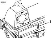
    Check Blower Housing/Impeller

    Maintenance Service IntervalMaintenance Procedure
    Before each use or daily
  • Check the blower housing/impeller.
    1. Stop engine, wait for all moving parts to stop, and remove key. Engage parking brake.

    2. Inspect for wear or damage daily. Replace or repair worn parts as needed.

      Note: When mowing in areas with sandy soil, use low lift blades on the cutting deck and higher cutting heights to minimize wear on the blower components.

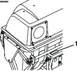
    Check Door Cloth Mesh

    Maintenance Service IntervalMaintenance Procedure
    Before each use or daily
  • Check door cloth mesh.
    1. Stop engine, wait for all moving parts to stop, and remove key. Engage parking brake.

    2. Inspect the door cloth mesh for wear, tears, or damage.

      Warning

      Under normal use the cloth mesh will deteriorate and wear. Objects could exit through worn cloth mesh at high speeds. Thrown objects can cause serious injury or kill you or bystanders.

      Check cloth mesh frequently for tears and holes. Replace worn cloth mesh.

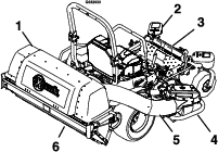
    Check Exhaust Diverter

    Maintenance Service IntervalMaintenance Procedure
    Before each use or daily
  • Check exhaust diverter.
  • Caution

    The exhaust diverter is hot. Touching a hot exhaust diverter can cause severe burns.

    Allow the exhaust diverter to cool completely before performing maintenance.

    1. Stop engine, wait for all moving parts to stop, and remove key. Engage parking brake.

    2. Inspect and remove debris from the exhaust diverter daily.

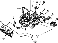
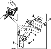
    Lubricate Grease Fittings

    Maintenance Service IntervalMaintenance Procedure
    Every 25 hours
  • Lubricate grease fittings.
  • Note: See chart for service intervals.

    1. Stop engine, wait for all moving parts to stop, and remove key. Engage parking brake.

    2. Lubricate fittings with NLGI grade #2 multi-purpose gun grease.

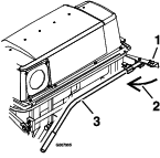
      Refer to the following chart for fitting locations and lubrication schedule.
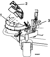
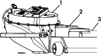
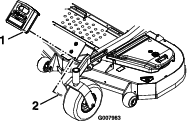
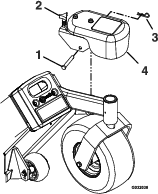
      Lubrication Chart
      Fitting LocationsInitial Pumps Number of Places Service Interval
      1. Idler Bushings1–2125 Hours
      2. Door Handle1–2125 Hours
      3. Lift Handle Pivot (11-Bushel Unit Only)1–21Yearly

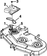
    Check Condition of Belt

    Maintenance Service IntervalMaintenance Procedure
    Every 50 hours
  • Check condition of belt.
  • All Units

    1. Stop engine, wait for all moving parts to stop, and remove key. Engage parking brake.

    2. Inspect the belt for damage or wear. Replace belt with one of the following:

      Deck Part No.
      48 inch1-653333
      52 inch1-653438
      60 inch103-0866
      72 inch103-0867

    Adjustments

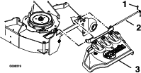
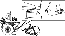
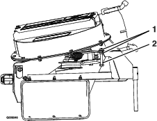
    Adjusting the Blower Drive Belt Position

    1. Read the operator’s manual for the UltraVac and mower before performing this adjustment. Make sure that you understand the controls, their locations their functions and safety requirements.

    2. Ensure the blower, belt cover, tubes and hopper are in good condition, properly attached and latched.

    3. Run the unit with the PTO and the blower engaged for two minutes.

    4. Disengage the PTO, stop the engine and remove the key.

    5. Remove the belt cover and check to make sure that the belt is riding near the center of the flat idler on the idler arm. If the belt is not riding near the center of the idler, remove the blower, and bend the idler arm slightly.

    6. Reinstall the blower and belt cover and perform steps 3-5 again to verify belt position.

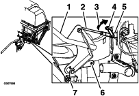
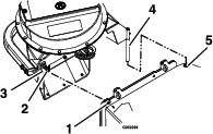
    Adjusting the Door Linkage

    7-Bushel Unit:

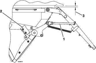
    1. If the door does not close properly adjust the rods as shown in Figure 23.

      • Shorten the rod to increase over center force.

      • Lengthen the rod to reduce.

      Adjust the rods on both sides so they are approximately equal.

      g009315
    2. If the left and right stops do not make contact with the door link when it is in the extended position:

      Adjust the position of the stops (see Figure 23) so that the door link contacts them when the upper tube of the door frame is within 1/4 inch (6.35 mm) ± 1/8 (3.2 mm) from the lower lip of the hopper.
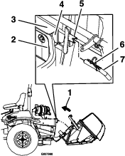
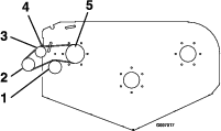
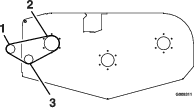
    11-Bushel Unit:

    g009316
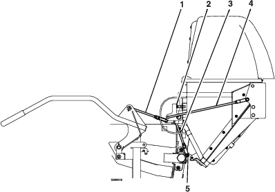
    1. Door closing: The closing of the door is controlled by the two hinge links and the two stop screws (see Figure 24). The stop screws should be adjusted so that both will be contacted when the contacting arm is straight up and down. With the stop screws adjusted, the length of the hinge links can be changed to provide complete closing of the door, and reasonable force on the handle to latch or unlatch the door. Lengthen the links to reduce the force. Shorten the links to increase the force. With the door closed, both links should be slightly tight to minimize rattling.

    2. Door opening: After adjusting the hinge links for door closing, the handle link can be adjusted to obtain maximum door opening (see Figure 24). Lengthen the link to open the door farther. Shorten the link to open the door less. The maximum door opening is limited by the contacting arm hitting the stop. This stop is non adjustable, and prevents over opening damage from occurring to the linkage.

    3. Latches: Once the open and closed positions have been set, the latches can be adjusted (see Figure 24). With the door closed, the latch link should be set so that the latch plate completely engages and contacts the latch rod welded to the door. The latch plates should not be tight against the latch rod. They should easily “wiggle”.

    Cleaning

    Clean Muffler and Rear Frame Area

    Maintenance Service IntervalMaintenance Procedure
    Before each use or daily
  • Clean muffler and rear frame area.
  • Stop engine, wait for all moving parts to stop, and remove key. Engage parking brake.

    Warning

    Operating engine parts, especially the muffler, become extremely hot. Severe burns can occur on contact and debris, such as leaves, grass, brush, etc. can catch fire.

    • Allow engine parts, especially the muffler, to cool before touching.

    • Remove accumulated debris from muffler, exhaust diverter, and engine area.

    Clean Rear Screen In Hopper

    Maintenance Service IntervalMaintenance Procedure
    Before each use or daily
  • Clean rear screen in the hopper.
    1. Stop engine, wait for all moving parts to stop, and remove key. Engage parking brake.

    2. Open door and remove clippings that are stuck to the screen.

    Clean Blower

    Maintenance Service IntervalMaintenance Procedure
    Yearly or before storage
  • Clean blower.
  • Grass build up may cause problems with the impeller when the unit is put back into operation.

    1. Stop engine, wait for all moving parts to stop, and remove key. Engage parking brake.

    2. Remove grass buildup from around the impeller before placing it in storage.

    Storage

    Handle Storage

    When storing the 7-Bushel unit, fold the handle inward as shown in Figure 25. Remove and retain the knob and carriage bolt from the handle bracket and rotate the handle bracket and rotate the handle inward.

    g007995

    When storing the 11-Bushel unit, either unlatch or remove the handle entirely from the unit (see step 9 in the Collection System Removal for Side Discharge section in Operation.)

    Troubleshooting

    Important: It is essential that all operator safety mechanisms be connected and in proper operating condition prior to mower use.

    When a problem occurs, Do Not overlook the simple causes. For example: starting problems could be caused by an empty fuel tank.

    The following table lists some of the common causes of trouble. Do Not attempt to service or replace major items or any items that call for special timing or adjustment procedures (such as valves, governor, etc.). Have this work done by your Engine Service Dealer.

    Note: When disconnecting electrical connectors Do Not pull on the wires to separate the connectors.

    ProblemPossible CauseCorrective Action
    Abnormal vibration.
    1. Cutting blade(s) is/are bent or unbalanced.
    2. Blade mounting bolt is loose.
    3. Loose blower pulley or pulley assembly.
    4. Blower impeller blades are bent.
    1. Install new cutting blade(s).
    2. Tighten the blade mounting bolt.
    3. Tighten the appropriate pulley.
    4. Contact an Authorized Service Dealer.
    Blower drive belt snaps or breaks frequently.
    1. Idler arm is out of alignment.
    1. Correct the alignment of the idler arm.
    Excessive grass blowout from the deck.
    1. Hopper is full.
    2. Plugged screen in bagger hopper.
    3. Ground speed is too fast.
    4. Blower belt is worn, loose, or broken.
    5. Plugged tube or blower.
    6. Conditions are dry.
    1. Dump more frequently.
    2. Remove debris, leaves or grass clippings from the screen.
    3. Drive slower at full throttle.
    4. Install new blower belt.
    5. Locate and remove plugged debris.
    6. Use lower lift blade.
    Blower and tubes plug too frequently.
    1. Hopper is too full.
    2. Ground speed is too fast.
    3. Grass is too wet.
    4. Grass is too long.
    5. Plugged screen in bagger hopper.
    6. Blower drive belt is worn, loose, or broken.
    7. Blower is plugged.
    1. Dump more frequently
    2. Drive slower at full throttle.
    3. Cut grass when it is dry.
    4. Cut grass more frequently or at higher cut height.
    5. Remove debris, leaves, or grass clippings from the screen.
    6. Install new belt.
    7. Use low lift blades in wet conditions.
    Blower impeller does not spin freely.
    1. Plugged blower.
    2. Impeller not aligned.
    1. Remove debris, leaves, or grass clippings from the blower impeller.
    2. Contact an Authorized Service Dealer.
    Plowing leaves.
    1. Deck is too low.
    1. Raise the deck slightly.
    Chasing leaves.
    1. Blowout from deck.
    2. Hopper is full.
    1. Check for clogged tubes.
    2. Dump more frequently.
    Blower components show signs of wear and/or air cleaners and cooling fins are dirty.
    1. Sand or dry conditions.
    1. Use low lift blades on the cutting deck and higher cutting heights.Clean air cleaners and cooling fins frequently.