


Maintenance
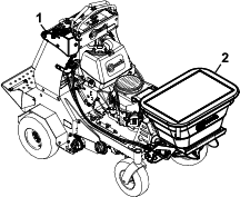
Note: Determine the left and right sides of the machine from the normal operating position.
Maintenance Safety
Warning
While maintenance or adjustments are being made, someone could start the engine. Accidental starting of the engine could seriously injure you or other bystanders.
Remove the key from the ignition switch, engage parking brake, and pull the wire(s) off the spark plug(s) before you do any maintenance to the unit or spreader attachment. Also push the wire(s) aside so it does not accidentally contact the spark plug(s).
-
Close the spreader gate, set the parking brake, stop engine and remove key or disconnect spark plug wire. Wait for all movement to stop before adjusting, cleaning or repairing.
-
Empty the hopper before tilting the machine for maintenance and before storing.
-
Keep the machine, guards, shields and all safety devices in place and in safe working condition. Frequently check for worn or deteriorating components and replace them with the manufacturer’s recommended parts when necessary.
Warning
Removal or modification of original equipment, parts and/or accessories may alter the warranty, controllability, and safety of the machine. Unauthorized modifications to the original equipment or failure to use original Exmark parts could lead to serious injury or death. Unauthorized changes to the machine, engine, fuel or venting system, may violate applicable safety standards such as: ANSI, OSHA and NFPA and/or government regulations such as EPA and CARB.
-
Use jack stands to support components when required.
Caution
Raising the machine for service or maintenance relying solely on mechanical or hydraulic jacks could be dangerous. The mechanical or hydraulic jacks may not be enough support or may malfunction allowing the machine to fall, which could cause injury.
Do not rely solely on mechanical or hydraulic jacks for support. Use adequate jack stands or equivalent support.
-
Keep hands and feet away from moving parts. If possible, Do Not make adjustments with the engine running. If the maintenance or adjustment procedure require the engine to be running and components moving, use extreme caution.
Warning
Contact with moving parts or hot surfaces may cause personal injury.
Keep your fingers, hands, and clothing clear of rotating components and hot surfaces.
-
Check all bolts frequently to maintain proper tightness.
Recommended Maintenance Schedule(s)
| Maintenance Service Interval | Maintenance Procedure |
|---|---|
| Before each use or daily |
|
Periodic Maintenance
Check for Loose Hardware
| Maintenance Service Interval | Maintenance Procedure |
|---|---|
| Before each use or daily |
|
-
Stop engine, wait for all moving parts to stop, and remove key. Engage parking brake.
-
Visually inspect machine for any loose hardware or any other possible problem. Tighten hardware or correct the problem before operating.
Adjustments
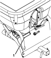
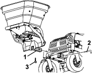
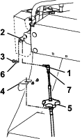
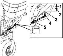
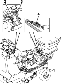
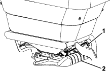
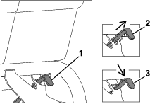
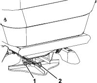
Spreader Pattern Control Cable Adjustment
To adjust the spreader pattern control cable:
-
Stop engine, wait for all moving parts to stop, and remove key. Engage parking brake.
-
Close the granular gate.
-
Make sure the spread pattern control handle is pushed down and locked at the control panel.
-
Loosen the jam nut at the end of the cable.
-
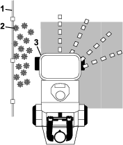
Pull the linkage rod until there is 1/8 inch (3.2 mm) gap between the ramp tooth and the impeller shaft.
-
Tighten the jam nut.
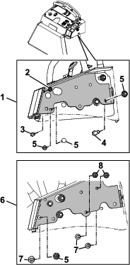
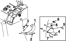
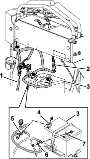
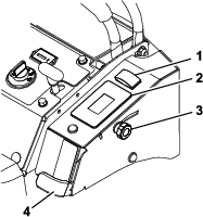
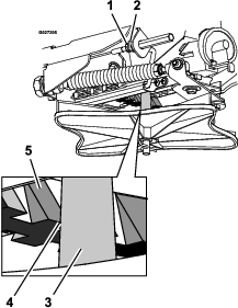
Adjusting the Gate Closure
-
If the gate arm is not fully closing, adjust the control cable:
-
knob located on the cable mount bracket
-
nuts located on either side of the hopper bracket
-
-
Continue to adjust until the gate can be fully closed; retighten all components.
Cleaning
Clean Debris From Machine
| Maintenance Service Interval | Maintenance Procedure |
|---|---|
| Before each use or daily |
|
-
Stop engine, wait for all moving parts to stop, and remove key. Engage parking brake.
-
Clean off any debris or build-up on the machine, especially the impeller.
Important: You can wash the machine with mild detergent and water. Do not pressure wash the machine. Avoid excessive use of water, especially near the control panel.