Safety
Safety and Instructional Decals
 |
Safety decals and instructions are easily visible to the operator and are located near any area of potential danger. Replace any decal that is damaged or missing. |
Setup
Preparing the Machine
-
Park the machine on a level surface.
-
Disengage the PTO, engage the parking brake, and move the motion-control levers outward to the NEUTRAL-LOCK position.
-
Shut off the engine and remove the key.
Removing the Existing Plates
-
Remove the fuel tank; refer to the Operator’s Manual for the machine.
-
Use the height-of-cut lever to lower the mower deck onto wood blocks.
-
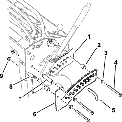
Remove both plates and fasteners as shown in Figure 1.
Installing the Latch Plate
Parts needed for this procedure:
| Latch plate | 1 |
| Shoulder bolt | 1 |
| Washer-head shoulder bolt | 1 |
| Washer | 2 |
| Nut (3/8 inch) | 1 |
| Nut (1/4 inch) | 1 |
| Wear plug | 1 |
-
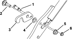
Remove the latch from the height-of-cut lever (Figure 2).
-
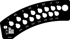
Cut out the template at the end of this publication and align it on the lever (Figure 3).

-
Drill a hole (3/8 inch) into the lever at the location shown in Figure 3.
-
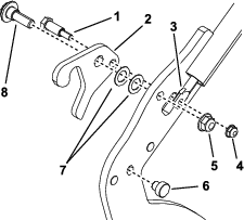
Install the new latch plate using 1 shoulder bolt, 1 washer-head shoulder bolt, 2 washers, 1 nut (3/8 inch), 1 nut (1/4 inch) as shown in Figure 4.
Note: Ensure that the washers seat onto the shoulder of the bolt and are not pinched between the height-of-cut lift arm and the shoulder of the bolt.
-
Torque the shoulder bolt to 1017 to 1243 N∙cm (90 to 110 in-lb) and torque the washer-head shoulder bolt to 41 to 49 N∙m (30 to 36 ft-lb).
-
Install the wear plug into the lever (Figure 4).
Installing the New Plates
Parts needed for this procedure:
| Spacer (1.7 inches) | 2 |
| Spacer (2.7 inches) | 1 |
| Inner plate | 1 |
| Spacer (0.7 inch) | 2 |
| Outer plate | 1 |
| Washer | 3 |
| Bolt (3/8 x 3-3/4 inches) | 3 |
| Nut (3/8 inch) | 4 |
| Pin | 1 |
-
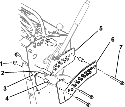
Install the inner and outer plates to the machine using the spacers, washers, bolts, and nuts as shown in Figure 5.
-
Install the pin in the hole for your desired height of cut.