Note: If the Low Flow Hydraulic Kit is equipped on your machine, the trimmer rack cannot be installed.
Preparing the Machine
-
Park the machine on a level surface.
-
Disengage the PTO.
-
Move the motion-control levers to the NEUTRAL-LOCK position.
-
Engage the parking brake.
-
Shut off the engine and remove the key.
Installing the Trimmer Rack
Parts needed for this procedure:
| Upper mount bracket | 1 |
| Lower mount bracket | 1 |
| Upper clamp mount | 1 |
| Lower clamp mount | 1 |
| Large clamp | 1 |
| Small clamp | 1 |
| Large backer plate | 1 |
| Small backer plate | 1 |
| Carriage bolt (5/16 inch) | 2 |
| Flange nut (5/16 inch) | 2 |
| Spacer | 1 |
| Carriage bolt (1/4 inch) | 4 |
| Flange nut (1/4 inch) | 8 |
| Hex-head bolt (1/4 x 1-1/2 inch) | 2 |
| Hex-head bolt (3/8 inch) | 3 |
| Flange nut (3/8 inch) | 5 |
| Hex-head bolt (1/4 x 1-1/4 inch) | 2 |
Note: Adjust the upper and lower plates to fit your trimmer as needed.
Installing the Upper Bracket Assembly
-
Lower the rear cushion and remove the fuel tank; refer to your machine Operator’s Manual.
-
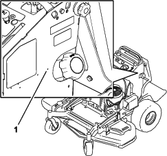
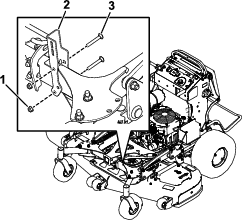
Locate and drill a 3/8-inch hole into the pilot hole on the left side of the machine (Figure 1).
-
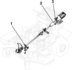
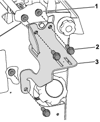
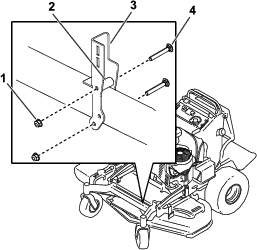
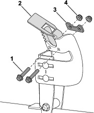
Use 3 hex-head bolts (3/8 inch), and 3 flange nuts (3/8 inch) to secure the upper mount bracket to the machine (Figure 2).
Torque the bolts to 37 to 45 N∙m (27 to 33 ft-lb).
-
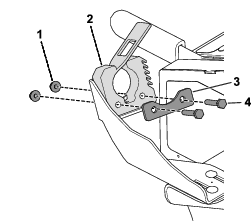
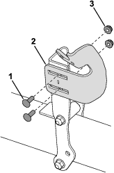
Use 2 carriage bolts (1/4 inch) and 2 flange nuts (1/4 inch) to secure the upper clamp mount to the upper mount bracket (Figure 3).
Torque the bolts to 10 to 12 N∙m (90 to 110 in-lb).
-
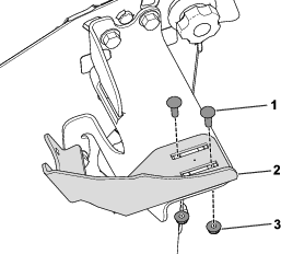
Use 2 hex-head bolts (1/4 x 1-1/2 inch) and 2 flange nuts (1/4 inch) to secure the large backer plate and the large clamp to the upper clamp mount (Figure 4).
Torque the bolts to 10 to 12 N∙m (90 to 110 in-lb).
Installing the Lower Bracket Assembly
-
Install the lower mount bracket to the frame on the left side of your machine as follows:
-
GrandStand Multi Force machines:
Use 2 carriage bolts (5/16 inch) and 2 flange nuts (5/16 inch) to install the lower mount bracket to the frame on the left side of the machine (Figure 5).
Torque the bolts to 20 to 25 N∙m (175 to 225 in-lb).
-
GrandStand machines:
Use 2 carriage bolts (5/16 inch), 2 flange nuts (5/16 inch), and a spacer to install the lower mount bracket to the frame on the left side of the machine (Figure 6).
Torque the bolts to 20 to 25 N∙m (175 to 225 in-lb).
-
-
Use 2 carriage bolts (1/4 inch) and 2 flange nuts (1/4 inch) to secure the lower adjustment plate to the mount bracket (Figure 7).
Torque the bolts to 10 to 12 N∙m (90 to 110 in-lb).
-
Use 2 hex-head bolts (1/4 x 1-1/4 inch), 2 flange nuts (1/4 inch), and a small backer plate to secure the small clamp to the clamp mount (Figure 8).
Torque the bolts to 10 to 12 N∙m (90 to 110 in-lb).
Using the Trimmer Rack
Figure 9 illustrates the correct position of the trimmer on the rack.
Note: Position the upper trimmer handle so that it is held in place by the upper clamp.