Introduction

This machine is intended to be used by professional, hired operators in commercial applications. It is designed primarily for working large areas on well-maintained lawns in parks, golf courses, sports fields, and on commercial grounds.

Read this information carefully to learn how to operate and maintain your product properly and to avoid injury and product damage. You are responsible for operating the product properly and safely.

Visit www.Toro.com for more information, including safety tips, training materials, accessory information, help finding a dealer, or to register your product.

Whenever you need service, genuine Toro parts, or additional information, contact an Authorized Service Dealer or Toro Customer Service and have the model and serial numbers of your product ready.Figure 1 and Figure 2 identify the location of the model and serial numbers on the product. Write the numbers in the space provided.

Important: With your mobile device, you can scan the QR code on the serial number plate (if equipped) to access warranty, parts, and other product information.

g262223
g262224

This manual identifies potential hazards and has safety messages identified by the safety alert symbol (Figure 3), which signals a hazard that may cause serious injury or death if you do not follow the recommended precautions.

g000502

This manual uses 2 words to highlight information. Important calls attention to special mechanical information and Note emphasizes general information worthy of special attention.

Warning

CALIFORNIA

Proposition 65 Warning

Use of this product may cause exposure to chemicals known to the State of California to cause cancer, birth defects, or other reproductive harm.

Safety

General Safety

This product is capable of amputating hands and feet and of throwing objects. Always follow all safety instructions to avoid serious personal injury.

Using this product for purposes other than its intended use could prove dangerous to you and bystanders.

  • Read and understand the contents of this Operator’s Manual before using the machine.

  • Use your full attention while operating the machine. Do not engage in any activity that causes distractions; otherwise, injury or property damage may occur.

  • Do not put your hands or feet near moving components of the machine.

  • Do not operate the machine without all guards and other safety protective devices in place and functioning properly on the machine.

  • Keep clear of any discharge opening. Keep bystanders and pets a safe distance away from the machine.

  • Keep children, bystanders, and pets out of the operating area. Never allow children to operate the machine.

  • Always shut off the engine of the tractor, remove the key (if equipped), wait for all moving parts to stop, and allow the machine to cool before adjusting, servicing, cleaning, or storing the machine.

Improperly using or maintaining this machine can result in injury. To reduce the potential for injury, comply with these safety instructions and always pay attention to the safety-alert symbol Graphic, which means Caution, Warning, or Danger—personal safety instruction. Failure to comply with these instructions may result in personal injury or death.

You can find additional safety information where needed throughout this Operator’s Manual.

Safety and Instructional Decals

Graphic

Safety decals and instructions are easily visible to the operator and are located near any area of potential danger. Replace any decal that is damaged or missing.

decal93-6696
decal110-4665
decal110-4666
decal110-4678
decal110-4667
decal110-4668
decal110-4670
decal92-1581
decal110-4677
decal110-4664
decal92-1582
decal106-8856
decal133-8061

Setup

Inspecting the Machine

ProCore 864

Use the following list as a reference:

  • 30 PTO horsepower minimum when used in light to normal conditions (sandy to sandy/loam soils with average compaction)

  • 35 PTO horsepower minimum when used in normal to heavy conditions (heavy loam, clay, and rocky soils with above average compaction)

  • Category I or II 3-point hitch, rated to lift at least a 714 kg (1575 lb) implement

  • 540 rpm tractor PTO

  • Adequate front-end weight (ballast)

  • Correct tire pressure

    Caution

    Do not exceed the maximum or minimum tractor tire inflation pressures as recommended by tire manufacturer.

ProCore 1298

Use the following list as a reference:

  • 45 PTO horsepower minimum when used in light to normal conditions (sandy to sandy/loam soils with average compaction)

  • 50 PTO horsepower minimum when used in normal to heavy conditions (heavy loam, clay, and rocky soils with above average compaction)

  • Category II 3 point hitch, rated to lift at least a 1043 kg (2300 lb) implement

  • 540 rpm tractor PTO

  • Adequate front-end weight (ballast)

  • Correct tire pressure

    Caution

    Do not exceed the maximum or minimum tractor tire inflation pressures as recommended by tire manufacturer.

Tractor Components (Figure 4)

g007332

Ballast Requirements

Warning

Mounting the ProCore aerator to the rear of the tractor will decrease the weight on the front axle.

Failure to add required ballast may result in an accident and severe injury or death.

  • To ensure adequate steering control and stability it may be necessary to add ballast to the front of the tractor.

  • Refer to the tractor operator's manual for ballast requirements.

Connecting the Lower Link Arms

Parts needed for this procedure:

Lynch pin2
  1. Ensure that the aerator is positioned on a flat, level surface for installation.

  2. Back the tractor squarely up to the aerator until the lower link arms are aligned with the hitch pins.

  3. Make sure that the PTO is disengaged.

  4. Engage the parking brake, shut off the engine, and remove the key from the ignition. Wait for the engine and all moving parts to stop before leaving the operator's seat on the tractor.

    Note: For maximum ground clearance, the hitch pins should be secured in the lower mounting holes (Figure 5). To determine when to use the upper mounting holes, refer to setup procedure Connecting the PTO Shaft.

    g028741
  5. Insert the right and left lower link arms onto the hitch pins (Figure 6).

    g007292
  6. Secure the lower link arms to the hitch pins with the lynch pins (Figure 6).

Connecting the Upper Link

Parts needed for this procedure:

Link pin1
Lynch pin1

Note: The front of the aerator must be vertical while operating for best aeration hole quality (Figure 7). Adjust the upper link to control this angle. Refer to Operating Tips for additional information.

g007293
  1. Connect the upper link to the lower hole in the bracket and secure it with the link pin and the lynch pin (Figure 8).

    g007294
  2. Grease the threaded steel upper link tubes.

  3. Rotate the upper link to tighten the link. Adjust it until the front of the aerator frame is 90 degrees from horizontal (Figure 8).

  4. Tighten the locknut to secure the upper link into position.

Connecting the PTO Shaft

Parts needed for this procedure:

Bolt (1/2 x 3 inches)1
Nut (1/2 inch)1
Short driveshaft, Part No. 115-2839 (may be needed; sold separately)

Important: Refer to the PTO shaft owner’s manual for additional operating and safety information.

Important: If necessary, install the short driveshaft, Part No. 115-2839 (sold separately). In most cases, the short driveshaft is not needed.

Refer to Figure 9 and determine the position of the PTO output shaft on the tractor, relative to the position of the lower trailing arms. This distance is designated the “M” dimension. The standard driveshaft included with your aerator fits a tractor “M” dimension down to 48.89 cm (19.25 inches). If the “M” dimension is smaller, we offer an optional shorter PTO driveshaft assembly (Part No. 115-2839), which fits a tractor “M” dimension down to 39.37 cm (15.50 inches).

It may be helpful to place a straightedge across the ends of the trailing arms to determine the distance between them and the end of the PTO output shaft end. Consult your tractor operator’s manual for potential length adjustment capability in the tractor trailing arm design. Contact your authorized Toro distributor if you need any assistance to perform this measurement and to order the driveshaft (Part No. 115-2839), should it be required.

g028690
  1. On the ProCore 864 only, remove the lower PTO shield (Figure 10).

    g007295
  2. Connect the PTO shaft to the gearbox input shaft with a 1/2 x 3.00 inch bolt and a 1/2 inch nut (Figure 11).

    g007296
  3. Connect the PTO shaft to the tractor rear PTO shaft.

    g007328
  4. Slide the PTO shaft forward as far as the tractor allows.

  5. Pull back on the locking collar to secure the PTO shaft in place. Slide the PTO shaft back and forth to make sure that it is properly locked.

  6. On CE models only, connect the shield safety chains from the power shaft sections to the welded clips on the link arms. Make sure that the chains remain slack when the aerator is raised or lowered.

    Caution

    To help prevent bodily injury, keep all PTO shields in place. On CE models, connect the shield chains to link arms to prevent shields from rotating during operation.

  7. On the ProCore 864, install the lower PTO shield to the aerator.

  8. Verify that the telescoping tube has a minimum of 76 mm (3 inches) overlap when the aerator is raised to the maximum height.

    To check the overlap, measure the distance between the end shields, as shown in figure Figure 13. This dimension must not exceed 406 mm (16 inches). If so, move the lower lift pins to the upper set of holes prior to operation.

    g007297

Adjusting the Sway Links

The ProCore 864 is designed to be offset from the tractor center line. The PTO shaft is offset 40 mm (1.57 inches) to the left of center and the aerator is offset 145 mm (5.70 inches) to the right of the center line. Adjust the sway links as required.

The ProCore 1298 is designed to be centered with the tractor center line. Adjust the sway links as required.

Adjust the sway links on the lower draft arms of the 3 point hitch to minimize side-to-side sway to a maximum of 25 mm (1 inch) on each side (Figure 14).

g007333

Adjust the lower links inboard until they contact the aerator mounting plates. This will reduce the stress on the pins. If the tractor has sway chains instead of sway links, it is recommended that washers be installed between the lower link arm and lynch pin to reduce the over hung load on the lift pins.

Note: Refer to the tractor operator's manual for additional installation and adjustment procedures.

Leveling the Aerator Side-to-Side

  1. Park the tractor and the aerator on a level, firm surface.

  2. Place a level on top of the aerator frame to check for level side-to-side (Figure 15).

    g007329
  3. Turn the adjustable link body (if provided) to raise or lower the link arm until the aerator is leveled side-to-side.

    Note: Refer to the tractor operator's manual for additional adjustment procedures.

Adjusting the Roller Scraper

Adjust the roller scraper so that there is a gap of approximately a 1 to 2 mm (0.06 to 0.09 inch) between the scraper and the roller.

  1. Loosen the fasteners securing each end of scraper to roller scraper tab (Figure 16).

    g007330
  2. Slide the roller scraper in or out until the required position is attained, and tighten the fasteners.

  3. On the ProCore 864 only, you can adjust the stop bolt on the center support to attain the proper gap.

Installing the Tine Heads and the Tines

A wide selection of tines and tine heads are available for the aerator. Choose the tine type, size, and spacings required for the job. Install the tine head and tines per the Installation Instructions supplied with each tine kit. Refer to Figure 21 and Figure 22 for the accessories.

Important: Never operate the aerator without the tine heads installed. The arms may move excessively and damage the aerator frame.

Installing the Turf Guards

Parts needed for this procedure:

Turf guards (not included)

A wide selection of turf guards are available for the aerator. Use the appropriate turf guards for the selected tine heads.

  1. Loosen the nuts securing the turf guard clamps to the turf guard tool bar (Figure 17).

    g007331
  2. Slide the appropriate turf guard under the turf guard clamp.

  3. Adjust the turf guards, left to right, to maintain equal distance to the tines within each slot.

  4. Tighten the nuts securing the turf guard.

  5. Mount the remaining turf guards and secure the turf guard clamps.

    Important: From the rear of the machine, check that the tines line up with the center of the gaps in the turf guards.

Securing the Hood Latches (CE only)

Parts needed for this procedure:

CE Compliance Kit, Part No. 110-4693 (not included)1

Note: The CE Completion Kit, Part No. 110-4693 is required to complete this step.

  1. On the ProCore 864 model, install a lock bracket over the left and right rear lower hood and upper hood latches with a tap bolt (4 total); refer to Figure 18.

    g007299
  2. On the ProCore 1298 model, install a lock bracket over all the rear lower hood latches and the outside upper hood latch on both the right and the left rear covers with a tap bolt (3 per coring head, 6 total); refer to Figure 18).

  3. Using a pliers or adjustable wrench, thread an internal lock washer onto each bolt (1 to 2 threads) to secure the latch (Figure 18).

Removing the Storage Stands

Parts needed for this procedure:

Lynch pin (ProCore 864)4
Lynch pin (ProCore 1298)8
  1. Raise the aerator 7.6 to 15.2 cm (3 to 6 inches) off the ground.

  2. Remove the nuts and the lock washers securing the storage stands to the aerator (Figure 19).

    g007303
  3. Remove the storage stands.

  4. Insert the lynch pins (included in loose parts) into the stand pins for storage (Figure 19).

  5. Use the storage stands whenever the aerator is removed from the tractor.

Product Overview

Depth Adjuster

Rotate the depth adjuster input shaft clockwise to reduce the aeration depth or counterclockwise to increase the aeration depth (Figure 20).

g007304

Note: 17 revolutions of the depth adjuster equals approximately 6.4 mm (1/4 inch) depth change.

Note: Specifications and design are subject to change without notice.

ProCore 864 Aerator

Working Width163 cm (64 inches)
Overall Width170 cm (67 inches)
Overall Length89 cm (35 inches)
Overall Height98 cm (38.5 inches)
Weight714 kg (1,575 lb)

ProCore 1298 Aerator

Working Width249 cm (98 inches)
Overall Width257 cm (101 inches)
Overall Length89 cm (35 inches)
Overall Height98 cm (38.5 inches)
Weight1043 kg (2,300 lb)

Attachments/Accessories

A selection of Toro approved attachments and accessories is available for use with the machine to enhance and expand its capabilities. Contact your Authorized Service Dealer or authorized Toro distributor or go to www.Toro.com for a list of all approved attachments and accessories.

To ensure optimum performance and continued safety certification of the machine, use only genuine Toro replacement parts and accessories. Replacement parts and accessories made by other manufacturers could be dangerous, and such use could void the product warranty.

g028725
g028724

Operation

Note: Determine the left and right sides of the machine from the normal operating position.

Before Operation

Before Operation Safety

General Safety

  • Never allow children or untrained people to operate or service the machine. Local regulations may restrict the age of the operator. The owner is responsible for training all operators and mechanics.

  • Become familiar with the safe operation of the equipment, operator controls, and safety signs.

  • Always shut off the engine of the tractor, remove the key, wait for all moving parts to stop, and allow the machine to cool before adjusting, servicing, cleaning, or storing the machine.

  • Know how to stop the machine and shut off the engine quickly.

  • Do not operate the machine without all guards and other safety protective devices in place and functioning properly on the machine.

  • Before operating, always inspect the machine to ensure that the tines are in good working condition. Replace worn or damaged tines.

  • Inspect the area where you will use the machine and remove all objects that the machine could strike.

  • Locate and mark all electrical or communication lines, irrigation components, and other obstructions in the area to be aerated. Remove the hazards, if possible, or plan how to avoid them.

  • Ensure that your tractor is suitable for use with an implement of this weight by checking with your tractor supplier or manufacturer.

OutCross Traction Unit Controls

Refer to the OutCross traction unit Operator’s Manual for information on controls and operation, as well as additional information on setting up the aerator.

Adjusting the Aeration Depth

Caution

Adjust the aeration depth only when the tractor is parked, the parking brake is engaged, the engine is off and the PTO is disengaged.

  1. Lay the desired tine onto the depth decal while aligning the tine tip with the desired aeration depth as shown in Figure 23.

    decal106-8856
  2. Determine the letter setting aligned with the mounting end of the tine (Figure 23). Adjust the depth control to the corresponding letter on the decal.

  3. Insert a 9/16-inch socket with a ratchet onto the depth adjuster input shaft (Figure 24).

    g007304
  4. Push in on the socket or use your hand to press on the locking plate.

  5. Rotate the depth adjuster clockwise to reduce the aeration depth or counterclockwise to increase the aeration depth. (Figure 24).

  6. Rotate the depth adjuster input shaft until the desired depth is attained as shown on the depth indicator decal (Figure 24).

    Note: 17 revolutions of the depth adjuster input shaft equals approximately 6.4 mm (1/4 inch) depth change.

Understanding the Tractor Controls

It is necessary to familiarize yourself with the operation of the following tractor controls before you are able to operate the aerator:

  • PTO engagement

  • 3 point hitch (raise/lower)

  • Clutch

  • Throttle

  • Gear selection

  • Parking brake

    Important: Refer to the tractor operator's manual for operating instructions.

Understanding the Principles of Operation

The 3-point hitch linkage of the tractor lifts the aerator for transport and lowers it for operation.

The power take-off (PTO) power from the tractor is transmitted via shafts, a gearbox, and drive belts to a number of crankshafts which drive the tine holding arms into the turf surface.

As the tractor travels forward with the PTO engaged and the machine lowered, a series of holes are created in the turf surface.

The penetration depth of the tines is determined by the height of the depth control.

The distance between the holes created is determined by the gear ratio (or hydrostatic traction pedal position) of the tractor and the number of tines in each tine head. Simply changing engine rpm does not change hole spacing.

Practicing the Operating Procedures

Important: When connecting the PTO, ensure that the aerator is not lifted higher than is necessary. Lifting the machine too high will cause the PTO shaft knuckles to break (Figure 25). The PTO can operate up to an angle of 25°, but can never exceed a 35° angle when the aerator is at its highest position, or severe shaft damage may occur.

g194609

Before using the aerator, find a clear area and practice operating the tractor with the aerator attached. Operate the tractor at recommended gear settings and PTO drive speeds and become thoroughly familiar with the aerator/tractor handling. Practice stopping and starting, raising and lowering the aerator, disengaging the PTO drive and aligning the machine with previous passes. A practice session ensures confidence in the performance of the aerator and helps ensure use of proper operating techniques wherever the machine is operated.

If there are sprinkler heads, electrical or communication lines, or other obstructions in the area to be aerated, mark these items to ensure that they are not damaged during operation.

Caution

To avoid personal injury, never leave the tractor seat without first disengaging the PTO drive, engaging the parking brake and shutting off the engine. Never perform aerator repairs without first lowering the aerator onto the storage stand or appropriate blocking or jacks. Ensure that all safety devices are secured in proper place before resuming operation.

Preparing to Aerate

Inspect the area of operation for hazards that could damage the machine and remove them, if possible, or plan how to avoid them. Carry replacement tines and tools in case tines are damaged due to contact with foreign materials.

During Operation

During Operation Safety

General Safety

  • The owner/operator can prevent and is responsible for accidents that may cause personal injury or property damage.

  • Wear appropriate clothing, including eye protection; slip-resistant, substantial footwear; long pants; and hearing protection. Tie back long hair and do not wear loose clothing or loose jewelry.

  • Do not operate the machine when tired, ill, or under the influence of alcohol or drugs.

  • Never carry passengers on the machine and keep bystanders and pets away from the machine during operation.

  • Operate the machine only in good visibility to avoid holes or hidden hazards.

  • Keep your hands and feet away from the tines.

  • Look behind and down before backing up to be sure of a clear path.

  • Stop the machine, shut off the engine, wait for all moving parts to stop, and inspect the tines after striking an object or if there is an abnormal vibration in the machine. Make all necessary repairs before resuming operation.

  • The aerator is heavy. When attached to a tractor and in the raised position, its weight affects stability, braking and steering. Exercise caution when transporting between working areas.

  • Always maintain proper tractor tire pressure.

  • Ensure that you comply with all regulations before transporting equipment on the public roads and highways. Make sure that all required reflectors and lights are in place and are clean and visible by overtaking and oncoming traffic.

  • Do not allow passengers to ride on the machine.

  • Reduce speed on rough roads and surfaces

  • Independent wheel brakes should always be locked together when transporting.

  • For all PTO shaft steel parts (tubes, bearings, joints, etc.) disassembly or repairs, it is highly advisable to contact your local Toro distributor. Removal of components for repairs and reassembly may damage some parts if not performed with special tools by trained technicians.

  • The PTO shaft must not be used without the guards supplied.

  • Friction clutches may become hot during use. Do not touch. To avoid the risk of fire, keep the area around the clutch free of flammable material and avoid prolonged slipping of the clutch.

Slope Safety

  • Review the tow vehicle specifications to ensure that you do not exceed its slope capabilities.

  • Slopes are a major factor related to loss of control and rollover accidents, which can result in severe injury or death. You are responsible for safe slope operation. Operating the machine on any slope requires extra caution.

  • Evaluate the site conditions to determine if the slope is safe for machine operation including surveying the site. Always use common sense and good judgment when performing this survey.

  • Review the slope instructions listed below for operating the machine on slopes and review the conditions to determine whether you can operate the machine in the conditions on that day and at that site. Changes in the terrain can result in a change in slope operation for the machine.

  • Avoid starting, stopping, or turning the machine on slopes. Avoid making sudden changes in speed or direction. Make turns slowly and gradually.

  • Do not operate a machine under any conditions where traction, steering, or stability is in question.

  • Remove or mark obstructions such as ditches, holes, ruts, bumps, rocks, or other hidden hazards. Tall grass can hide obstructions. Uneven terrain could overturn the machine.

  • Be aware that operating the machine on wet grass, across slopes, or downhill may cause the machine to lose traction. Loss of traction to the drive wheels may result in sliding and a loss of braking and steering.

  • Use extreme caution when operating the machine near drop offs, ditches, embankments, water hazards, or other hazards. The machine could suddenly roll over if a wheel goes over the edge or the edge caves in. Establish a safety area between the machine and any hazard.

Operating the Machine

Note: When using needle tine heads, make sure to read the instructions included with the kit for unique operating procedures.

  1. Lower the aerator on the 3 point linkage so that the tines are nearly to the ground at the lowest part of their stroke.

  2. At a low tractor engine rpm, engage the power take off (PTO) clutch to start the aerator working.

    Important: Never operate the aerator without the tine heads installed.

  3. Select a gear that gives a forward speed of approximately 1 to 4 km/h (0.6 to 2.5 mph) at the rated PTO speed of 540 rpm (refer to the tractor operator's manual).

  4. As the clutch is released and the tractor moves forward, lower the machine fully into the turf and increase engine speed to give a maximum of 540 rpm at the PTO.

    Important: Never operate the tractor PTO in excess of 540 rpm or damage to the aerator could occur.

    Note: Make sure that the roller is on the ground.

  5. Note the hole pattern. If you require greater hole spacing, increase forward the speed of the tractor by shifting up a gear or with a hydrostatic drive tractor, actuate the hydrostat lever or pedal to give faster speed. For closer hole spacing, decrease tractor forward speed. Changing engine speed, in a particular gear, will not change the hole pattern.

    Important: Look backward frequently to ensure that the machine is operating properly and alignment is maintained with previous passes.

  6. Use the front tractor wheel as a guide to maintain equal lateral hole spacing with the previous pass.

  7. At the end of the aeration pass, raise the aerator and disengage the PTO.

  8. If you back into a tight area (like a tee box), disengage the PTO and raise the aerator to the highest position. Use caution not to catch the turf guards on the turf.

  9. Always clear the area of all damaged machine parts, such as broken tines, etc., to prevent anything from being picked up and thrown by mowers or other turf maintenance equipment.

  10. Replace broken tines, inspect and correct damage to those still usable. Repair any other machine damage before commencing operation.

Adjusting the Hole Spacing

The forward hole spacing is determined by the tractor gear ratio (or the hydrostatic traction pedal). Changing the engine speed does not change the forward hole spacing.

The lateral hole spacing is determined by the number of tines in the tine heads.

Hole spacingGround speed
mm (inch)km/h (mph)
25 (1)0.6 (0.4)0.6 (0.4)0.6 (0.4)0.6 (0.4)0.6 (0.4)0.6 (0.4)0.6 (0.4)0.6 (0.4)0.8 (0.5)0.8 (0.5)0.8 (0.5)0.8 (0.5)0.8 (0.5)
32 (1.25)0.8 (0.5)0.8 (0.5)0.8 (0.5)0.8 (0.5)0.8 (0.5)0.8 (0.5)0.8 (0.5)1.0 (0.6)1.0 (0.6)1.0 (0.6)1.0 (0.6)1.0 (0.6)1.0 (0.6)
38 (1.5)1.0 (0.6)1.0 (0.6)1.0 (0.6)1.0 (0.6)1.0 (0.6)1.0 (0.6)1.1 (0.7)1.1 (0.7)1.1 (0.7)1.1 (0.7)1.1 (0.7)1.1 (0.7)1.1 (0.7)
44 (1.75)1.1 (0.7)1.1 (0.7)1.1 (0.7)1.1 (0.7)1.1 (0.7)1.1 (0.7)1.3 (0.8)1.3 (0.8)1.3 (0.8)1.3 (0.8)1.3 (0.8)1.3 (0.8)1.3 (0.8)
51 (2)1.3 (0.8)1.3 (0.8)1.3 (0.8)1.3 (0.8)1.3 (0.8)1.4 (0.9)1.4 (0.9)1.4 (0.9)1.4 (0.9)1.4 (0.9)1.4 (0.9)1.6 (1.0)1.6 (1.0)
57 (2.25)1.4 (0.9)1.4 (0.9)1.4 (0.9)1.4 (0.9)1.4 (0.9)1.6 (1.0)1.6 (1.0)1.6 (1.0)1.6 (1.0)1.6 (1.0)1.8 (1.1)1.8 (1.1)1.8 (1.1)
64 (2.5)1.6 (1.0)1.6 (1.0)1.6 (1.0)1.6 (1.0)1.6 (1.0)1.8 (1.1)1.8 (1.1)1.8 (1.1)1.8 (1.1)1.9 (1.2)1.9 (1.2)1.9 (1.2)1.9 (1.2)
70 (2.75)1.6 (1.0)1.8 (1.1)1.8 (1.1)1.8 (1.1)1.8 (1.1)1.9 (1.2)1.9 (1.2)1.9 (1.2)1.9 (1.2)2.1 (1.3)2.1 (1.3)2.1 (1.3)2.1 (1.3)
76 (3)1.8 (1.1)1.9 (1.2)1.9 (1.2)1.9 (1.2)2.1 (1.3)2.1 (1.3)2.1 (1.3)2.1 (1.3)2.3 (1.4)2.3 (1.4)2.3 (1.4)2.3 (1.4)2.4 (1.5)
83 (3.25)1.9 (1.2)2.1 (1.3)2.1 (1.3)2.1 (1.3)2.3 (1.4)2.3 (1.4)2.3 (1.4)2.3 (1.4)2.4 (1.5)2.4 (1.5)2.4 (1.5)2.6 (1.6)2.6 (1.6)
89 (3.5)2.1 (1.3)2.3 (1.4)2.3 (1.4)2.3 (1.4)2.4 (1.5)2.4 (1.5)2.4 (1.5)2.6 (1.6)2.6 (1.6)2.6 (1.6)2.7 (1.7)2.7 (1.7)2.7 (1.7)
95 (3.75)2.3 (1.4)2.4 (1.5)2.4 (1.5)2.4 (1.5)2.6 (1.6)2.6 (1.6)2.6 (1.6)2.7 (1.7)2.7 (1.7)2.7 (1.7)2.9 (1.8)2.9 (1.8)3.1 (1.9)
102 (4)2.4 (1.5)2.6 (1.6)2.6 (1.6)2.6 (1.6)2.7 (1.7)2.7 (1.7)2.7 (1.7)2.9 (1.8)2.9 (1.8)3.1 (1.9)3.1 (1.9)3.1 (1.9)3.2 (2.0)
108 (4.25)2.6 (1.6)2.7 (1.7)2.7 (1.7)2.7 (1.7)2.9 (1.8)2.9 (1.8)3.1 (1.9)3.1 (1.9)3.1 (1.9)3.2 (2.0)3.2 (2.0)3.2 (2.0)3.4 (2.1)
114 (4.5)2.7 (1.7)2.9 (1.8)2.9 (1.8)2.9 (1.8)3.1 (1.9)3.1 (1.9)3.2 (2.0)3.2 (2.0)3.2 (2.0)3.4 (2.1)3.4 (2.1)3.5 (2.2)3.5 (2.2)
121 (4.75)2.9 (1.8)3.1 (1.9)3.1 (1.9)3.1 (1.9)3.2 (2.0)3.2 (2.0)3.4 (2.1)3.4 (2.1)3.5 (2.2)3.5 (2.2)3.5 (2.2)3.7 (2.3)3.7 (2.3)
127 (5)3.1 (1.9)3.2 (2.0)3.2 (2.0)3.2 (2.0)3.4 (2.1)3.4 (2.1)3.5 (2.2)3.5 (2.2)3.7 (2.3)3.7 (2.3)3.9 (2.4)3.9 (2.4)4.0 (2.5)
133 (5.25)3.2 (2.0)3.4 (2.1)3.4 (2.1)3.4 (2.1)3.5 (2.2)3.5 (2.2)3.7 (2.3)3.7 (2.3)3.9 (2.4)3.9 (2.4)4.0 (2.5)4.0 (2.5)4.2 (2.6)
140 (5.5)3.4 (2.1)3.4 (2.1)3.5 (2.2)3.5 (2.2)3.7 (2.3)3.7 (2.3)3.9 (2.4)3.9 (2.4)4.0 (2.5)4.0 (2.5)4.2 (2.6)4.2 (2.6)4.3 (2.7)
146 (5.75)3.5 (2.2)3.5 (2.2)3.7 (2.3)3.9 (2.4)3.9 (2.4)4.0 (2.5)4.0 (2.5)4.2 (2.6)4.2 (2.6)4.3 (2.7)4.3 (2.7)4.5 (2.8)4.5 (2.8)
152 (6)3.7 (2.3)3.7 (2.3)3.9 (2.4)4.0 (2.5)4.0 (2.5)4.2 (2.6)4.2 (2.6)4.3 (2.7)4.3 (2.7)4.5 (2.8)4.5 (2.8)4.7 (2.9)4.7 (2.9)
PTO rpm420430440450460470480490500510520530540

Aerating Hard Ground

If the ground is too firm to obtain the desired coring depth, the coring head can get into a “bouncing” rhythm. This is due to the tines attempting to penetrate the hard pan. This condition can be corrected by attempting one or more of the following:

  • Best results are obtained after a rain or when turf has been watered the previous day.

  • Reduce the number of tines per stomper arm. Attempt to maintain a symmetrical tine configuration to evenly load the stomper arms.

  • Reduce aerator penetration (depth setting) if the ground is hard packed. Clean up the cores, water the turf, and aerate again at a deeper penetration.

Aeration of soil types built on top of hard subsoils (i.e. sand/soil cap placed over rocky ground) can cause undesired hole quality. This is caused when the aeration depth is greater than the soil cap and the subsoil is too hard to penetrate. When the tines contact this subsoil the aerator may lift and cause the top of the holes to become elongated. Reduce the aeration depth sufficiently to avoid penetration into the hard subsoil.

Using Needle Tines

Long slender tines used in either a needle tine head or mini tine head can leave the front or rear of the hole tufted or slightly deformed. Hole quality for this configuration generally improves if the coring head speed is reduced 10 to 15% from full operating speed. For PTO powered aerators reduced the engine speed until the PTO speed is around 460 to 490 rpm. The forward spacing is not effected by reducing the engine speed. The pushed hole can also be affected by the position of the rotalink damper assembly. Refer to Adjusting the Rotalink Assembly.

Avoiding Root Zone Lifting

Using the mini-tine heads in conjunction with larger coring tines or large diameter solid tines can induce significant stress on the root zone of the turf. This stress can fracture the root zone and cause a lifting action to the turf. If this damage occurs try one or more of the following:

  • Reduce the tine density (remove some of the tines).

  • Decrease the coring depth (suggested in 1/2 inch increments).

  • Increase the forward hole spacing (change the tractor transmission up one gear).

  • Decrease the tine diameter (solid or coring).

Adjusting the Rotalink Assembly

The mounting height of the rotalink damper assembly affects the reactive force applied to the stomper arm and ground engagement during aeration. In the event of the front of the hole being pushed (elongated or dimpled), a “stiffer” position can help resist this push and improve hole quality. In the event of the back of the hole being pushed (elongated or dimpled) a “softer” position can improve the hole quality.

To adjust the rotalink assembly, proceed as follows:

  1. Remove the 2 locknuts (1/2 inch) securing the rotalink damper assembly to the underside of the coring head frame (Figure 26).

  2. Lower the damper assembly to expose the spacers (Figure 26).

  3. Move 1 or 2 spacers per side from the damper assembly to the top of the coring head frame. Each spacer is equivalent to 1/2 inch. The lower bumper spacer must remain on the damper assembly.

    g007335
  4. Assemble the damper assembly to the coring head frame again. Ensure that the D washer is installed against the coring head frame as shown in Figure 26. Secure the 2 locknuts.

    To see the effects of this adjustment, adjust only 3 to 4 assemblies to compare the original position and the new position on a trial pass. When satisfactory results are achieved, move the remaining assemblies to the same height as the desired arms.

Operating Tips

Caution

To avoid personal injury, never leave the tractor seat without first disengaging the PTO drive, setting the parking brake and stopping the engine. Never perform aerator adjustments or repairs without first lowering the aerator onto the safety stand. Be sure all safety devices are secured in proper place before resuming operation.

  • Engage the PTO at low engine speed. Increase engine speed to achieve PTO speed of 540 rpm (maximum) and the lower aerator. Operate at an engine rpm that the aerator runs most smoothly.

    Note: Changing engine/PTO rpm in a particular tractor gear (or fixed hydrostatic pedal position on tractors with hydrostatic transmission) will not change hole spacing.

  • Make very gradual turns when aerating. Never make sharp turns with the PTO drive engaged. Plan your aeration path before lowering the aerator.

  • If the tractor “bogs” down when operating on hard ground or going uphill, raise the aerator slightly until the speed is regained, then lower the aerator again.

  • Do not aerate if the ground is too hard or dry. Best results are obtained after a rain or when turf has been watered the previous day.

    Note: If the roller rides up off the ground while aerating, the ground is too hard to achieve the desired depth; reduce the aeration depth until the roller contacts the ground during operation.

  • Raise the aerator penetration if the ground is hard packed. Clean up cores and aerate at deeper penetration, preferably after watering.

  • The ProCore 864 aerator is offset to the tractor's right side to allow aerating without driving over the cores with the tractor tires. Whenever possible, aerate with the longer offset towards the previous aeration pass.

  • Always check/adjust the top link whenever you change the aeration depth. The front of the aerator should be vertical.

  • Look backward frequently to ensure that the machine is operating properly and alignment is maintained with previous passes.

  • Always clear the area of all damaged machine parts, such as broken tines, etc., to prevent them from being picked up and thrown by mowers or other turf maintenance equipment.

  • Replace broken tines, and inspect and correct damage to those still usable. Repair any other machine damage before commencing operation.

After Operation

After Operation Safety

General Safety

  • Keep all parts of the machine in good working condition and all hardware tightened.

  • Replace all worn, damaged, or missing decals.

Transporting the Machine

To begin transport operation, raise the aerator and disengage the PTO. To avoid loss of control, traverse steep inclines slowly, approach rough areas at reduced speed and cross severe undulations carefully.

Important: Do not exceed transport speeds of 24 km/h (15 mph).

Cleaning the Machine after Use

After daily use, thoroughly wash the machine with a garden hose without a nozzle to avoid contamination and seal and bearing damage due to excessive water pressure. You can use a brush to remove caked-on material. Use mild detergent to clean the covers. After cleaning, grease all drive lines and roller bearings, inspect for machine damage, oil leakage, and component and tine wear.

Remove, clean, and oil the tines. Spray a light oil mist on the coring head bearings (crank and damper links).

Maintenance

Recommended Maintenance Schedule(s)

Maintenance Service IntervalMaintenance Procedure
After the first 8 hours
  • Change the gearbox lubrication.
  • Check the torque of the coring head fasteners.
  • Before each use or daily
  • Check the belt tension.
  • Check the belt tension.
  • Every 50 hours
  • Grease the bearings and bushings.
  • Inspect the bearings.
  • Every 100 hours
  • Check the gearbox lubrication.
  • Every 250 hours
  • Change the gearbox lubrication.
  • Check the torque of the coring head fasteners.
  • Every 500 hours
  • Inspect and replace the bearings as needed.
  • Before storage
  • Perform all 50-hour maintenance procedures.
  • Paint areas that are scratched, chipped, or rusted.
  • Remove and clean the tines.
  • Remove all debris.
  • Yearly
  • Inspect the belts.
  • Maintenance Safety

    • Before adjusting, cleaning, servicing, or leaving the machine, do the following:

      • Position the machine on a level surface.

      • Move the throttle switch to the low-idle position.

      • Disengage the PTO.

      • Ensure that the traction is in neutral.

      • Engage the parking brake.

      • Shut off the engine of the tractor and remove the key.

      • Wait for all moving parts to stop.

      • Allow machine components to cool before performing maintenance.

    • Perform only those maintenance instructions described in this manual. If major repairs are ever needed or assistance is desired, contact an authorized Toro distributor.

    • Ensure that the machine is in safe operating condition by keeping nuts, bolts, and screws tight.

    • If possible, do not perform maintenance while the engine is running. Keep away from moving parts.

    • Do not check or adjust the chain tension when the tractor engine is running.

    • Carefully release pressure from components with stored energy.

    • Support the machine with blocks or storage stands when working beneath it. Never rely on the hydraulic system to support the machine.

    • Check the tine mounting bolts daily to be sure that they are tightened to specification.

    • Ensure that all guards are installed and the hood is secured shut after maintaining or adjusting the machine.

    • To ensure safe, optimal performance of the machine, use only genuine Toro replacement parts. Replacement parts made by other manufacturers could be dangerous, and such use could void the product warranty.

    Jacking the Machine

    Caution

    If the machine is not properly supported by blocks or jack stands, the machine may move or fall, which may result in personal injury.

    When changing attachments or performing other service, use correct blocks, hoists or jacks. Ensure that the machine is parked on a solid, level surface such as a concrete floor. Prior to raising the machine, remove any attachments that may interfere with the safe and proper raising of the machine. Always chock or block the tow vehicle wheels. Use jack stands or solid wood blocks to support the raised machine.

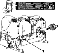
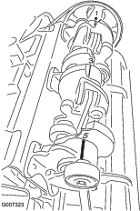
    Note: If available, a hoist can be used to lift the rear of the ProCore Aerator. Use the eyelets in the coring head bearing housings as hoist attachment points (Figure 27)

    g007308

    Greasing the Bearings and Bushings

    Maintenance Service IntervalMaintenance Procedure
    Every 50 hours
  • Grease the bearings and bushings.
  • The main working bearings of the aerator are sealed for life and require no maintenance or lubrication. This drastically reduces the maintenance required and eliminates the risk of grease or oil being dropped onto the turf.

    There are grease fittings that must be lubricated with an SAE multi-purpose, high-temperature grease with high-pressure (EP) performance or SAE multi-purpose lithium-based grease.

    The lubrication points are:

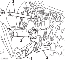
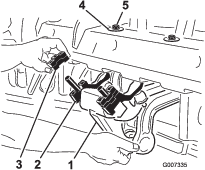
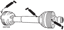
    PTO shaft (3) (Figure 28)

    g007309

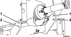
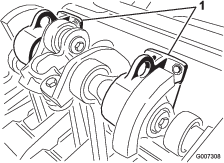
    Roller bearings (ProCore 864: 2; ProCore 1298: 4) (Figure 29)

    g007310

    Drive shaft bearings (ProCore 864:1; ProCore 1298: 2) (Figure 30)

    g007311

    Important: Bearings rarely fail from defects in materials or workmanship. The most common reason for failure is moisture and contamination working its way past the protective seals. Bearings that are greased will rely upon regular maintenance to purge harmful debris from the bearing area. Sealed bearings rely on an initial fill of special grease and a robust integral seal to keep contaminants and moisture out of the rolling elements.

    The sealed bearings require no lubrication or short term maintenance. This minimizes routine service required and reduces the potential of turf damage due to grease contamination. These sealed bearing packages will provide good performance and life under normal use, but periodic inspections of bearing condition and seal integrity should be conducted to avoid downtime. These bearings should be inspected seasonally and replaced if damaged or worn. Bearings should operate smoothly with no detrimental characteristics such as high heat, noise, looseness, or rust weeping.

    Due to the operating conditions these bearing/seal packages are subject to (i.e. sand, turf chemicals, water, impacts, etc.) they are considered normal wear items. Bearings that fail due to other than defects in materials or workmanship are typically not covered under warranty.

    Note: Bearing life can be negatively affected by improper washing procedures. Do not wash the unit when it is still hot and avoid directing high-pressure or high-volume spray at the bearings.It is common for new bearings to purge some grease out of the seals on a new machine. This purged grease will turn black in color due to collection of debris and not due to excessive heat. It is good practice to wipe this excess grease from the seals after the initial 8 hours. There may always appear to be a wet area around the seal lip. This is generally not detrimental to bearing life, but keeps the seal lip lubricated.Coring head bearing replacement is suggested at intervals of 500 hours. A bearing service kit which covers the complete coring head is available from your distributor.

    Checking the Gearbox Lubrication

    Maintenance Service IntervalMaintenance Procedure
    Every 100 hours
  • Check the gearbox lubrication.
  • The gearbox is filled with 80W-90 gear oil or equivalent. Allow the gearbox to cool before checking the lubrication.

    1. Clean debris from the fill plug and check the plug to avoid contamination.

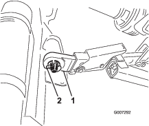
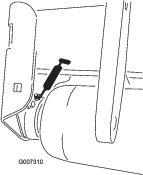
    2. Remove the check plug from the gearbox (Figure 31).

      g007312
    3. Make sure that the oil level is up to the bottom of the check plug hole in gearbox (Figure 31).

    4. If the oil level is low, remove the fill plug from the gearbox and add oil as required.

    5. Install the plugs.

    Changing the Gearbox Lubrication

    Maintenance Service IntervalMaintenance Procedure
    After the first 8 hours
  • Change the gearbox lubrication.
  • Every 250 hours
  • Change the gearbox lubrication.
  • The gearbox is filled with 80W-90 gear oil or equivalent.

    1. Clean debris from the fill plug and the drain cap to avoid contamination (Figure 31).

    2. Remove the fill plug to relieve air draw.

    3. Position a drain pan under the drain tube and remove the drain cap.

      Note: The high viscosity of cool oil extends the drain time (approximately 30 minutes).

    4. After oil is completely drained, install the drain cap.

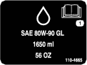
    5. Fill the gearbox with 1650 ml (56 fl oz) of high quality 80W-90 gear lube.

    6. Install the fill plug.

    7. Check the oil level.

    Checking the Coring Head Fastener Torque

    Maintenance Service IntervalMaintenance Procedure
    After the first 8 hours
  • Check the torque of the coring head fasteners.
  • Every 250 hours
  • Check the torque of the coring head fasteners.
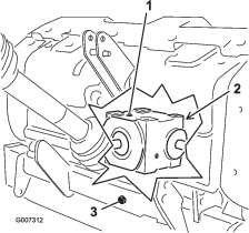
  • After the initial 8 hours of use, check the coring head fasteners to ensure that proper torque is maintained. Fastener torque requirements are listed on the reference service decal below and located on the coring head.

    decal110-4664

    Inspecting the Belts

    Maintenance Service IntervalMaintenance Procedure
    Yearly
  • Inspect the belts.
  • The drive belt(s) on the ProCore Aerators have been designed to be very durable. However, the normal exposure to UV radiation, ozone or incidental exposure to chemicals can deteriorate the rubber compounding over time and lead to premature wear or material loss (i.e. chunking).

    Annual belt inspection is highly recommended for signs of wear, excessive cushion cracks, or large embedded debris with replacement when needed.

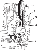
    Adjusting the Belt Tension

    Maintenance Service IntervalMaintenance Procedure
    Before each use or daily
  • Check the belt tension.
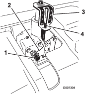
  • Make sure that the belt is properly tensioned to ensure correct operation of the machine and to prevent unnecessary wear.

    1. Check for proper belt tension by compressing idler spring to a length of 146 mm (5-3/4 inches); refer to Figure 33.

      decal110-4667
    2. Adjust the belt tension as follows:

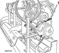
      1. Remove the rear coring head cover (Figure 34).

        g007316
      2. Remove the pulley shield mounting bolts and remove the shield (Figure 34).

      3. Loosen the locknut securing the spring retainer (Figure 35).

        g007315
      4. Adjust the spring retainer to attain required compressed spring length (Figure 35).

      5. Tighten the locknut against the spring retainer to lock the adjustment.

      6. Install the pulley shield and the coring head cover.

    Replacing the Drive Belt

    Note: You do not need to remove the outside stomper arm to replace the drive belt.

    Removing the Belt

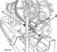
    1. Remove the rear coring head cover (Figure 36).

      g007316
    2. Remove the pulley shield mounting bolts and remove the shield (Figure 36).

    3. Remove the fasteners securing the dirt shield and the lower belt shield (Figure 37). Remove the dirt shield and the lower belt shield.

      g007317
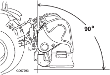
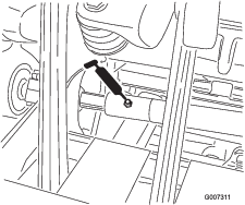
    4. To release the idler spring tension, loosen the locknut securing the spring retainer (Figure 38) and rotate the spring retainer.

      g007319

      Caution

      Springs are under tension, use caution when adjusting or removing.

    5. Loosen and remove the 2 locknuts and washers securing the rotalink damper for the #1 stomper arm (Figure 39).

      g007320
    6. Lower the rotalink damper from the coring head frame.

    7. Route the drive belt down through the coring head frame and around the lower end of the #1 stomper arm (Figure 39).

    Installing the Belt

    1. Route the new drive belt around the lower end of the #1 stomper arm and up through the coring head frame.

    2. Position the drive belt onto the crank pulley, under the idler assembly and over the drive pulley.

    3. Raise the rotalink damper for the #1 stomper arm to coring head frame. Ensure that the damper spacers are installed in the same position as in removal.

    4. Secure the rotalink damper to the coring head with the 2 washers and locknuts previously removed.

    5. Install and adjust the belt idler pulley and adjust it to the appropriate tension.

    6. Install the dirt shield and the lower belt shield. Adjust the lower shield to ensure clearance with the belt.

    7. Install the pulley and the coring head covers.

    Adjusting the Side Shield

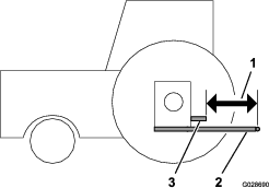
    The coring head side shields should be adjusted so that the bottom rides between 25 to 38 mm (1 to 1-1/2 inches) from the turf while aerating.

    1. Loosen the bolts and nuts securing the side shield to frame (Figure 40).

      g007322
    2. Adjust the shield up or down and tighten the nuts.

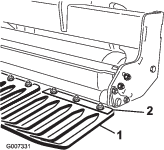
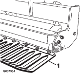
    Replacing the Turf Guards

    All turf guards (Figure 41) should be replaced if broken or worn to less than 1/4 inch thickness. Broken turf guards can catch and tear turf, creating undesirable damage.
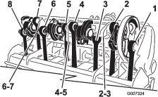
    g007334

    Coring Head Timing

    The unitized coring head design of the ProCore aerators provides industry-leading smooth operation while taking out the guesswork of timing.

    ProCore 864 (Figure 42)

    Each pair of crank arms joined through a bearing housing are timed 180 degrees apart (i.e. arm positions 1-2, 3-4, 5-6, 7-8). The adjacent pairs are all set with the same timing whereas the later pair lags by 120 degrees. The same pair of coupling castings are used between all adjacent pairs (i.e. coupling positions 2-3, 4-5, 6-7). To further reduce operating vibration, 2 counter weights are added at the #1 position on the pulley and the #8 position.

    Note: The numbers cast into the crank arms will not align with the raised indicator mark on the bearing housings for the ProCore 864.

    g007324

    ProCore 1298 (Figure 43)

    This unit is comprised of 2 independent coring heads with 6 arms each. The timing of either coring head is not dependent on the adjacent coring head. The timing marks are easily identified by the numbers cast into the crank arm castings and the raised locator on the bearing housings. The #1 arm always starts with the drive pulley.

    g007323

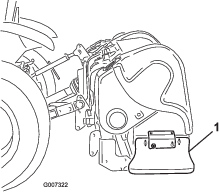
    Removing the Aerator from the Tractor

    Important: Refer to the PTO shaft owner’s manual for additional operating and safety information.

    1. Park the vehicle on a level surface, not on a slope.

    2. Disengage the PTO and engage the parking brake.

    3. Shut off the engine and remove the key from the ignition switch.

    4. Before leaving the operator's seat, wait for the engine and all moving parts to stop.

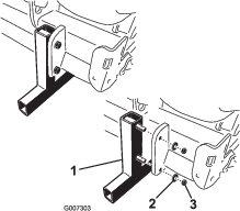
    5. Install the storage stands and secure them to the aerator with the lynch pins (Figure 44).

      g007302

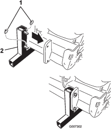
      Note: The aerator can be stored on the original shipping pallet.

    6. Slowly lower the aerator until the storage stands contact the ground.

    7. Loosen the locking nut and rotate the upper adjusting link to release the tension between the aerator and the tractor.

    8. Remove the lynch pin and the top link pin securing the center link to the bracket. Retain the lynch pin and the top link pin with the aerator.

    9. Disconnect the safety shield chains from the tractor PTO (CE only).

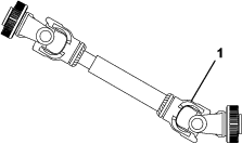
    10. Pull back on the lock collar to disconnect the power shaft from the tractor PTO shaft.

    11. Slide the PTO shaft back and remove it from the tractor.

    12. Connect the PTO tether to the PTO shield to prevent the PTO shaft from contacting the ground (Figure 45).

      g007307
    13. Remove the lynch pins and slide the lower link arms off the hitch pins. Retain the lynch pins with the aerator.

    Storage

    Storage Safety

    • Always shut off the engine of the tractor and remove the key. Wait for all movement to stop and allow the machine to cool before adjusting, cleaning, storing, or repairing it.

    • Store the machine on the storage stands positioned on a firm, level surface so that it does not sink or tip over.

    • Store the machine away from areas of human activity.

    • Do not allow children to play on or around the stored machine.

    Storing the Machine

    At the end of an aerating season or when the aerator will not be used for a long period, it is good practice to carry out the following preventive maintenance.

    1. Clean off any dirt or grease that may have accumulated on the aerator or any of the moving parts.

    2. Remove and clean out the tines. Coat the tines with oil to prevent rusting during storage.

    3. Open the hood and clean out the inside of the machine.

    4. Lubricate all grease fittings.

    5. Store the machine on the provided storage stands on a hard, dry surface.

    6. Tether the PTO shaft in the stored position to prevent damage, or remove the PTO and store it under the hood to minimize corrosion.

    7. Paint the roller and touch up any other scratches on the painted surfaces.

    8. Replace any missing or damaged decals.

    9. Store the aerator inside a dry, secure building. Inside storage reduces maintenance, gives a longer working life, and increases the residual value of the machine. If inside storage is not available, cover the machine with a heavy sheet or tarpaulin and secure it tightly.