
 ), which means Caution,
Warning, or Danger—personal safety instruction. Failure to comply
with these instructions may result in personal injury or death.
), which means Caution,
Warning, or Danger—personal safety instruction. Failure to comply
with these instructions may result in personal injury or death.


Maintenance
Caution
Failure to properly maintain the machine could result in premature failure of machine systems causing possible harm to you or bystanders.
Keep the machine well maintained and in good working order as indicated in these instructions.
Note: Determine the left and right sides of the machine from the normal operating position.
Maintenance Safety
-
Before cleaning, servicing, or adjusting the machine, do the following:
-
Park the machine on a level surface.
-
Shut off the traction unit engine, remove the key, and wait for all moving parts to stop.
-
Chock the wheels.
-
Allow machine components to cool before performing maintenance.
-
-
Perform only those maintenance instructions described in this manual. If major repairs are ever needed or you need assistance, contact an authorized Toro distributor.
-
Do not rely on a hydraulic system to support the machine; support the machine with blocks or jack stands when working beneath it.
-
Ensure that all guards are installed securely after maintaining or adjusting the machine.
-
Do not allow untrained personnel to service the machine.
-
Carefully release pressure from components with stored energy.
-
Keep all parts in good working condition and all fasteners tightened. Replace all damaged or missing decals.
-
Do not interfere with the intended function of a safety device or reduce the protection provided by a safety device. Check their proper operation regularly.
-
If major repairs are ever necessary or assistance is required, contact an authorized Toro distributor.
-
Altering this machine in any manner may affect the operation of the machine, performance, durability, or its use may result in injury or death. Such use could void the product warranty of The Toro® Company.
Recommended Maintenance Schedule(s)
| Maintenance Service Interval | Maintenance Procedure |
|---|---|
| Every 20 hours |
|
| Every 100 hours |
|
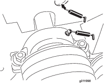
Lubrication
Greasing the Machine
The machine has grease fittings that you must lubricate regularly with No. 2 lithium grease.
Fan-Shaft Bearings
| Maintenance Service Interval | Maintenance Procedure |
|---|---|
| Every 100 hours |
|
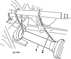
Grease the 2 fan shaft bearings (Figure 10).
Note: Remove belt cover to access rear fitting.
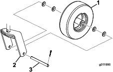
Caster Wheels
| Maintenance Service Interval | Maintenance Procedure |
|---|---|
| Every 100 hours |
|
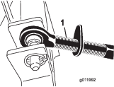
Grease the 2 caster wheel fittings (Figure 11).
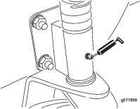
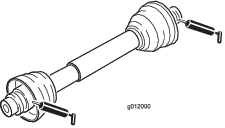
Drive Shaft
| Maintenance Service Interval | Maintenance Procedure |
|---|---|
| Every 100 hours |
|
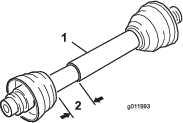
Grease the 2 drive-shaft fittings (Figure 12).
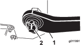
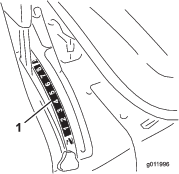
Belt Maintenance
Adjusting the Blower Belt
| Maintenance Service Interval | Maintenance Procedure |
|---|---|
| Every 20 hours |
|
Ensure that the belt is properly tensioned to ensure proper operation of the machine and unnecessary wear. Check the belt frequently.
Important: The fasteners on the covers of this machine are designed to remain on the cover after removal. Loosen all of the fasteners on each cover a few turns so that the cover is loose but still attached, then go back and loosen them until the cover comes free. This prevents you from accidentally stripping the bolts free of the retainers.
-
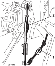
Remove the capscrews, washers, and nuts securing the belt guard to the blower housing (Figure 13).
Note: The drive shaft does not have to be disconnected to adjust the belt.
-
Remove the belt guard (Figure 13).
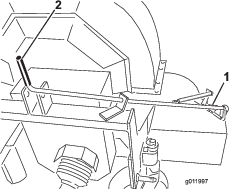
-
Remove capscrew and nut securing the tensioner guide to the blower frame (Figure 14).
Note: The belt tension releases when the capscrew is removed.
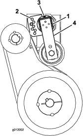
-
On the rear of the frame, loosen the capscrew securing the belt tensioner to frame (Figure 14).
-
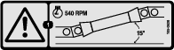
Position a large wrench on the tensioner and rotate the tensioner clockwise until the decal is aligned 15º on the tensioner tube.
-
Insert the capscrew into the aligned guide holes and secure it with the nut (Figure 14).
Note: If holes are not exactly aligned, rotate the guide to the next higher hole until it is aligned.
-
Tighten the capscrew on the rear of the frame to lock the tensioner.
-
Install the belt guard to the blower housing with the capscrews, washers, and nuts.