Setup
Preparing the Machine
-
Park the machine on a level surface.
-
Engage the parking brake.
-
Shut off the engine and remove the key.

Installing the Support Arm
Parts needed for this procedure:
| Support arm | 1 |
| Flange-head bolt (M6 x 35 mm) | 4 |
-
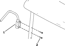
Apply medium-grade thread-locking compound to the threads of the 2 flange-head bolts (M6 x 35 mm).
-
Secure the support arm to the front mount tube using the 2 flange-head bolts (M6 x 35 mm) as shown in Figure 2.
Note: You can install the support arm in the upper or lower set of holes.
Installing the Support Arm
Parts needed for this procedure:
| Support arm | 1 |
| Flange-head bolt (M6 x 16 mm) | 4 |
| Extension bracket | 1 |
| Locknut (M6) | 2 |
-
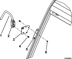
Apply medium-grade thread-locking compound to the threads of the 2 flange-head bolts (M6 x 16 mm).
-
Align the mounting bracket of the support arm to the extension bracket and the mirror bracket at pillar A of the cab (Figure 3).
-
Secure the extension bracket to the mirror bracket with 2 flange-head bolts (M6 x 16 mm) and 2 locknuts (M6) as shown in Figure 3.
-
Secure the support arm to the pillar with the 2 flange-head bolts (M6 x 16 mm) as shown in Figure 3.
-
Torque the bolts to 972 to 1,198 N∙cm (86 to 106 in-lb).
Installing the Support Arm
Parts needed for this procedure:
| Support arm | 1 |
| Flange-head bolt (M6 x 16 mm) | 4 |
-
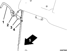
Apply medium-grade thread-locking compound to the threads of the 2 flange-head bolts (M6 x 16 mm).
-
Align the mounting bracket of the support arm to the mirror bracket at pillar A of the cab (Figure 4).
-
Secure the support arm to the pillar with the 2 flange-head bolts (M6 x 16 mm) as shown in Figure 4.
-
Torque the bolts to 972 to 1198 N∙cm (86 to 106 in-lb).
Installing the Mirror
Parts needed for this procedure:
| Mirror | 1 |
-
Align the mounting clamp of the mirror with the support arm (A of Figure 5).
-
Slip the mirror onto the support arm (A of Figure 5).
Note: Ensure that the support arm extends 13 mm (1/2 inch) beyond the mounting clamp.
-
Tighten the 2 capscrews (5 mm) for the mounting clamp (B of Figure 5) to a maximum torque of 300 N∙cm (26 in-lb).
Operation
Adjusting the Mirror
Important: Adjust the viewing angle of the mirror before you drive the machine.
-
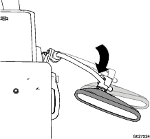
Use 2 hands to rotate the mirror clockwise or counterclockwise on its ball mount (Figure 6).
-
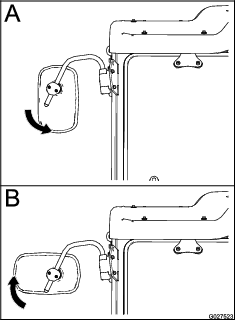
To adjust the position of the mirror and support arm, swing the support arm toward the cab or away from it (Figure 7).
-
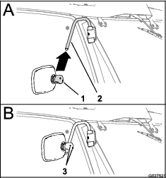
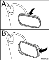
Use 2 hands to rotate the mirror up or down on its ball mount (A in Figure 8).
-
Use 2 hands to rotate the mirror left or right on its ball mount (B in Figure 8).