Safety
Safety and Instructional Decals
 |
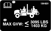
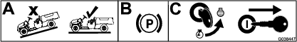
Safety decals and instructions are easily visible to the operator and are located near any area of potential danger. Replace any decal that is damaged or missing. |
Setup
Preparing the Machine
-
Park the machine on a level surface.
-
Engage the parking brake.
-
Shut off the engine and remove the key.
Removing the Plastic Cargo Bed
-
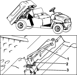
Using an overhead hoist, raise the plastic cargo bed.
-
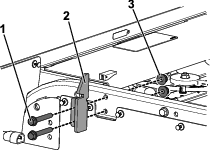
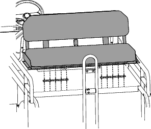
Remove the 3 flange-head screws (5/16 x 3/4 inch) and U-bracket from the prop rod (Figure 2).
Note: Retain the hardware to install the plastic cargo bed in the future.
-
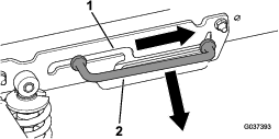
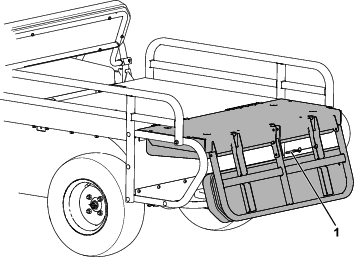
Slide the prop rod forward out of the detent slot and remove the prop rod (Figure 3).
-
Using an overhead hoist, lower the cargo bed.
-
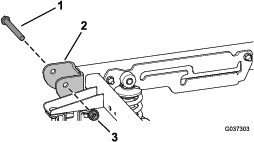
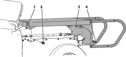
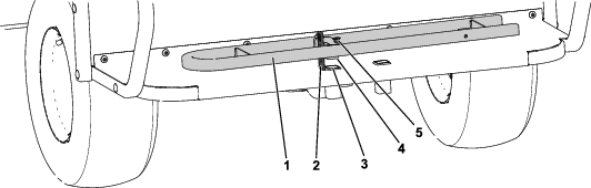
Remove the 2 pivot bolts (1/2 x 4-1/2 inches) and 2 locknuts (1/2 inch) from the pivot bracket located at the rear of the machine (Figure 4).
Note: Retain the hardware for installation of the flatbed assembly in 1 in Installing the Rear-Facing Seat.
-
Release the cargo-bed lever, then raise and remove the cargo bed using an overhead hoist.
-
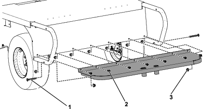
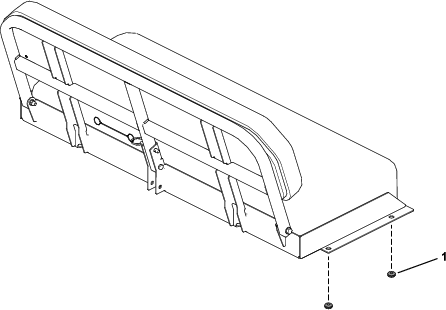
Remove the 2 bed latches from the frame of the machine by removing the 4 flange-head screws (3/8 x 2-1/2 inches) and 4 nuts (3/8 inch) as shown in Figure 5.
Note: Retain 2 flange-head screws (3/8 x 2-1/2 inches) and 2 nuts (3/8 inch) for installation of the flatbed assembly in step 1 in Installing the Rear-Facing Seat. Retain the remaining hardware to install the plastic cargo bed in the future.
Installing the Rear-Facing Seat
Parts needed for this procedure:
| Flatbed | 1 |
| Footrest | 1 |
| Carriage bolt (3/8 x 3 inches) | 10 |
| Hex nut (3/8 inch) | 17 |
| Button-head screw (3/8 x 1 inch) | 7 |
| Rear-seat handle | 1 |
| Hold-down strap | 1 |
| Countersunk screw (1/4 inch) | 2 |
| Locknut (1/4 inch) | 2 |
| Side rail | 2 |
| Rivet | 10 |
| Rubber grommet | 8 |
-
Install the flatbed onto the frame of the machine using the 2 pivot bolts (1/2 x 4-1/2 inches), 2 locknuts (1/2 inch), 2 flange-head screws (3/8 x 2-1/2 inches), and 2 nuts (3/8 inch) previously removed in steps 6 and 8 of Removing the Plastic Cargo Bed. Refer to Figure 6.
-
Attach the footrest onto the flatbed using 2 carriage bolts (3/8 x 3 inches), 7 button-head screws (3/8 x 1 inch), and 9 hex nuts (3/8 inch) as shown in Figure 7.
-
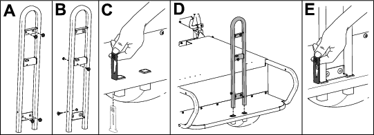
Install 4 rubber grommets onto the rear-seat handle (A of Figure 8).
-
Install 2 countersunk screws (1/4 inch) and 2 locknuts (1/4 inch) onto the rear-seat handle (B of Figure 8).
-
Feed the hold-down strap through the bottom of the footrest (C of Figure 8).
-
Install the rear-seat handle onto the footrest (D of Figure 8).
-
Secure the rear-seat handle to the footrest by pulling the hold-down strap up and around the countersunk screw (E of Figure 8).
-
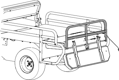
Install the side rails to the flatbed assembly with 8 carriage bolts (3/8 x 3 inches) and 8 hex nuts (3/8 inch) as shown in Figure 9.

-
Install 4 rubber grommets on the edges of the seat base as shown in Figure 10.
-
Install the seat assembly onto the flatbed, lining up the holes on the flatbed with the holes on the hinges, and secure the rivet seat assembly to the flatbed (Figure 11).
Folding the Rear-Facing Seat
-
Remove the rear-seat handle and lay it flat on the footrest lining up the tab on the handle with the handle hole on the footrest (Figure 12).
-
Secure the handle to the footrest using the hold-down strap and countersunk screw on the rear-seat handle (Figure 12).
-
Rotate the seat forward and remove the quick pin (Figure 13).
-
Fold the back rest support up and replace the quick pin as shown in Figure 14.
Note: The back rest support acts as a back tailgate.
Applying the Decals
Parts needed for this procedure:
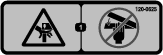
| Decal 120-0625 | 2 |
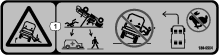
| Decal 138-5554 | 2 |
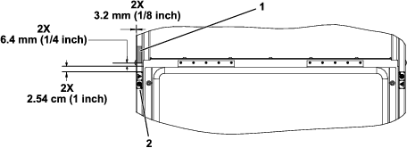
Apply the 2 pinch-point warning decals (120-0625) and 2 tipping hazard decals (138-5554) to the rear-facing seat frame using the measurements shown in Figure 15.