
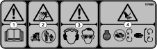
 , which means Caution, Warning,
or Danger—personal safety instruction. Failure to comply with
these instructions may result in personal injury or death.
, which means Caution, Warning,
or Danger—personal safety instruction. Failure to comply with
these instructions may result in personal injury or death.

Maintenance
Maintenance Safety
-
Park the machine on a level surface. Never allow untrained personnel to service the machine.
-
Use jack stands to support the machine when required.
-
Remove the key from the switch on the traction unit to prevent accidental starting of the engine when servicing, adjusting, or storing the machine.
-
Perform only those maintenance instructions described in this manual. If the blower requires a major repair, contact an authorized Toro distributor.
-
Ensure that the machine is in safe operating condition by keeping nuts, bolts, and screws tight.
-
Keep your hands and feet away from moving parts. Do not make adjustments with the engine running.
-
Keep all parts in good working condition and all hardware tightened. Replace all worn or damaged decals.
-
To ensure optimum performance and continued safety certification of the machine, use only genuine Toro replacement parts and accessories. Replacement parts and accessories made by other manufacturers could be dangerous, and such use could void the product warranty.
Checking the Belts
| Maintenance Service Interval | Maintenance Procedure |
|---|---|
| Every 300 hours |
|
Check the belts for cracks, frayed edges, burn marks, or any other damage. Replace damaged belts.
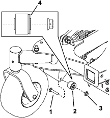
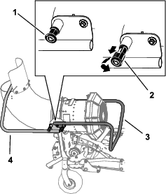
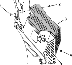
Replacing the Blower Belt
-
Park the machine on a level surface, disengage the PTO, and engage the parking brake.
-
Shut off the engine, remove the key, and wait for all moving parts to stop before leaving the operating position.
-
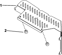
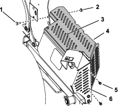
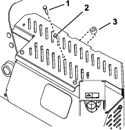
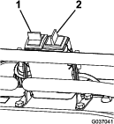
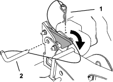
Remove the belt cover (Figure 31).
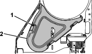
-
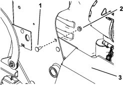
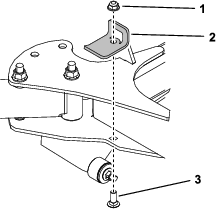
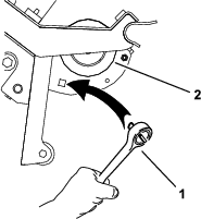
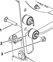
Loosen the nut on the top pulley and slide the pulley up to release tension on the belt (Figure 32).
-
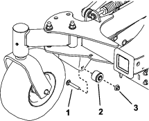
Remove the roller bearing (Figure 32).
-
Remove the belt and install a new belt (Figure 32).
-
Install the roller bearing (Figure 32)
-
Slide the top pulley down until the belt deflection is 5 mm (0.19 inch) at the center of the largest span and tighten the nut (Figure 32).
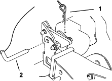
Replacing the Clutch Belt
-
Park the machine on a level surface, disengage the PTO, and engage the parking brake.
-
Shut off the engine, remove the key, and wait for all moving parts to stop before leaving the operating position.
-
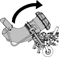
Lower the blower.
-
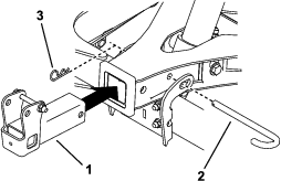
Loosen the nozzle clamp and remove the nozzle.
-
Remove the belt from the machine clutch.
Note: You can use a drive ratchet (1/2 inch) to move the left idler pulley (Figure 14).
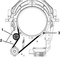
-
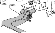
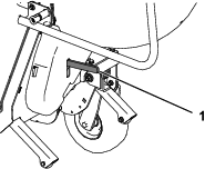
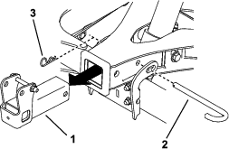
Remove the belt from the fan pulley (Figure 33).
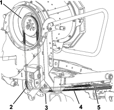
-
Route the belt down through the drive adapter assembly, around the idler pulleys, and around the clutch pulley (Figure 33). Ensure that the belt is seated properly in the pulley grooves.
Note: If needed, you may use a drive ratchet (1/2 inch) to move the left idler pulley (Figure 14).
Checking the Hydraulic Hoses
| Maintenance Service Interval | Maintenance Procedure |
|---|---|
| Every 100 hours |
|
Check the hydraulic hoses for leaks, loose fittings, kinked lines, loose mounting supports, wear, weather, and chemical deterioration.
Warning
Hydraulic fluid escaping under pressure can penetrate skin and cause injury. Fluid injected into the skin must be surgically removed within a few hours by a doctor familiar with this form of injury; otherwise, gangrene may result.
-
Ensure that all hydraulic-fluid hoses and lines are in good condition and all hydraulic connections and fittings are tight before applying pressure to the hydraulic system.
-
Keep your body and hands away from pinhole leaks or nozzles that eject high-pressure hydraulic fluid.
-
Use cardboard or paper to find hydraulic leaks; never use your hands.
Removing Debris from the Machine
| Maintenance Service Interval | Maintenance Procedure |
|---|---|
| After each use |
|
-
Park the machine on a level surface, disengage the PTO, and engage the parking brake.
-
Shut off the engine, remove the key, and wait for all moving parts to stop before leaving the operating position.
-
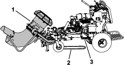
Clean debris from the drives, muffler, and engine after each use.