| Maintenance Service Interval | Maintenance Procedure |
|---|---|
| Before each use or daily |
|
Introduction
This rotary-blade, riding lawn mower is intended to be used by professional, hired operators. It is designed primarily for cutting grass on well-maintained lawns on residential or commercial properties. It is not designed for cutting brush or for agricultural uses.
Read this information carefully to learn how to operate and maintain your product properly and to avoid injury and product damage. You are responsible for operating the product properly and safely.
You may contact Toro directly at www.Toro.com for product safety and operation training materials, accessory information, help finding a dealer, or to register your product.
For the Operator’s Manual, the complete warranty details, or to register your product, use the QR code or visit www.Toro.com. You may also call us at 1-888-384-9939 to request a written copy of the product warranty.
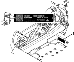
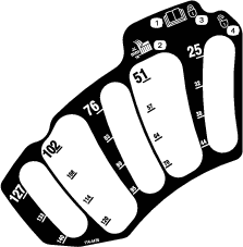
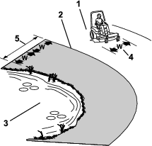
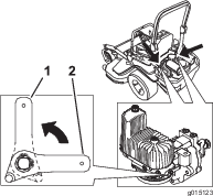
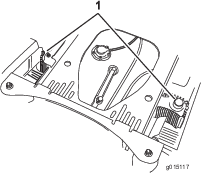
Whenever you need service, genuine Toro parts, or additional information, contact an Authorized Service Dealer or Toro Customer Service and have the model and serial numbers of your product ready. Figure 1 identifies the location of the model and serial numbers on the product. Write the numbers in the space provided.
Important: With your mobile device, you can scan the QR code (if equipped) on the serial number decal to access warranty, parts, and other product information.
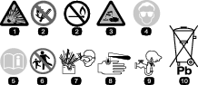
This manual identifies potential hazards and has safety messages identified by the safety-alert symbol (Figure 2), which signals a hazard that may cause serious injury or death if you do not follow the recommended precautions.

This manual uses 2 words to highlight information. Important calls attention to special mechanical information and Note emphasizes general information worthy of special attention.
This product complies with all relevant European directives; for details, please see the separate product specific Declaration of Conformity (DOC) sheet.
Gross or Net Torque: The gross or net torque of this engine was laboratory rated by the engine manufacturer in accordance with the Society of Automotive Engineers (SAE) J1940 or J2723. As configured to meet safety, emission, and operating requirements, the actual engine torque on this class of mower will be significantly lower.
Please refer to the engine manufacturer’s information included with the machine.
Warning
CALIFORNIA
Proposition 65 Warning
The engine exhaust from this product contains chemicals known to the State of California to cause cancer, birth defects, or other reproductive harm.
Battery posts, terminals, and related accessories contain lead and lead compounds, chemicals known to the State of California to cause cancer and reproductive harm. Wash hands after handling.
Use of this product may cause exposure to chemicals known to the State of California to cause cancer, birth defects, or other reproductive harm.
Safety
This machine has been designed in accordance with EN ISO 5395:2013.
General Safety
This product is capable of amputating hands and feet and of throwing objects. Always follow all safety instructions to avoid serious personal injury.
Using this product for purposes other than its intended use could prove dangerous to you and bystanders.
-
Always keep the roll bar in the fully raised and locked position and use the seat belt.
-
Do not operate the machine near drop-offs, ditches, embankments, water, or other hazards, or on slopes greater than 15 degrees.
-
Read and understand the contents of this Operator’s Manual before starting the engine.
-
Do not put your hands or feet near moving components of the machine.
-
Do not operate the machine without all guards and other safety protective devices in place and working on the machine.
-
Keep children and bystanders out of the operating area. Never allow children to operate the machine.
-
Stop the machine, shut off the engine, and remove the key before servicing, fueling, or unclogging the machine.
Improperly using or maintaining this machine can result in injury. To reduce the potential for injury, comply with these safety instructions and always pay attention to the safety-alert symbol, which means Caution, Warning, or Danger—personal safety instruction. Failure to comply with these instructions may result in personal injury or death.
You can find additional safety information where needed throughout this manual.
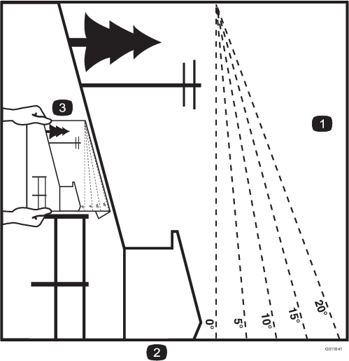
Slope Indicator
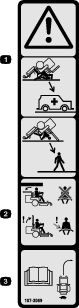
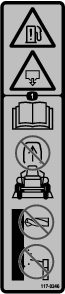
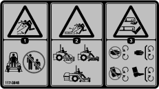
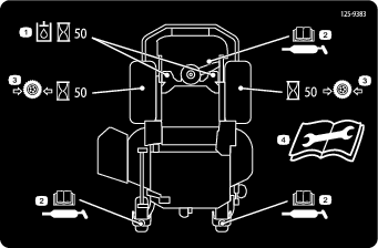
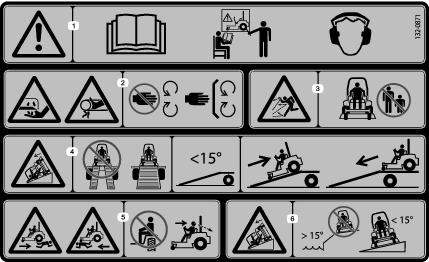
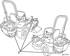
Safety and Instructional Decals
 |
Safety decals and instructions are easily visible to the operator and are located near any area of potential danger. Replace any decal that is damaged or missing. |


Product Overview
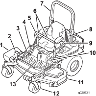
Become familiar with all the controls before you start the engine and operate the machine (Figure 4 and Figure 5).
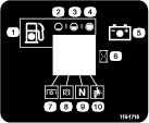
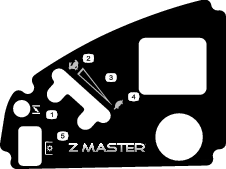
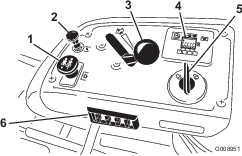
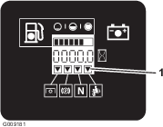
Control Panel
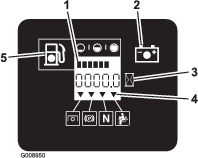
Hour Meter
The hour meter records the number of hours the engine has operated. It operates when the engine is running. Use these times for scheduling regular maintenance (Figure 6).
Fuel Gauge
The fuel gauge is located within the hour meter, and the bars light up when the key switch is in the ON position (Figure 6).
The indicator light appears when the fuel level is low (approximately 1 gallon remaining in the fuel tank).
Safety-Interlock Indicators
There are symbols on the hour meter that indicate with a black triangle that the interlock component is positioned correctly (Figure 6).
Battery-Indicator Light
If you turn the key switch to the ON position for a few seconds, the battery voltage displays in the area where the hours are normally displayed.
The battery light turns on when the ignition is turned on and when the charge is below the correct operating level (Figure 6).
Throttle Control
The throttle controls the engine speed, and it has a continuous-variable setting from the SLOW to FAST position (Figure 5).
Choke Control
Use the choke control to start a cold engine.
Blade-Control Switch (Power Takeoff)
The blade-control switch, represented by a power-takeoff (PTO) symbol, engages and disengages power to the mower blades (Figure 5).
Key Switch
The key switch, used to start and shut off the engine, has 3 positions: OFF, RUN, and START. Refer to Starting the Engine.
Motion-Control Levers
Use the motion-control levers to drive the machine forward, reverse, and turn either direction (Figure 4).
Neutral-Lock Position
Use the NEUTRAL-LOCK position with the safety-interlock system to engage and to determine the NEUTRAL position.
Fuel-Shutoff Valve
Close the fuel-shutoff valve when transporting or storing the machine; refer to Using the Fuel-Shutoff Valve.
Attachments/Accessories
A selection of Toro approved attachments and accessories is available for use with the machine to enhance and expand its capabilities. Contact your Authorized Service Dealer or authorized Toro distributor or go to www.Toro.com for a list of all approved attachments and accessories.
To ensure optimum performance and continued safety certification of the machine, use only genuine Toro replacement parts and accessories. Replacement parts and accessories made by other manufacturers could be dangerous, and such use could void the product warranty.
Note: Specifications and design are subject to change without notice.
Machines with Side Discharge
| 122 cm (48-inch) Deck | 132 cm (52-inch) Deck | 152 cm (60-inch) Deck | 72-inch Deck | |
|---|---|---|---|---|
| Without the deck | 116 cm | 116 cm | 135 cm | 150 cm |
| (46 inches) | (46 inches) | (53 inches) | (59 inches) | |
| Deflector up | 137 cm | 146 cm | 157 cm | 187 cm |
| (54 inches) | (58 inches) | (62 inches) | (74 inches) | |
| Deflector down | 161 cm | 172 cm | 192 cm | 222 cm |
| (64 inches) | (68 inches) | (76 inches) | (88 inches) |
| 122 cm (48-inch) Deck | 132 cm (52-inch) Deck | 152 cm (60-inch) Deck | 72-inch Deck | |
|---|---|---|---|---|
| Roll bar up | 201 cm | 201 cm | 211 cm | 219 cm |
| (79 inches) | (79 inches) | (83 inches) | (86 inches) | |
| Roll bar down | 206 cm | 206 cm | 215 cm | 223 cm |
| (81 inches) | (81 inches) | (85 inches) | (88 inches) |
| 122 cm (48-inch) Deck | 132 cm (52-inch) Deck | 152 cm (60-inch) Deck | 72-inch Deck | |
|---|---|---|---|---|
| Roll bar up | 179 cm | 179 cm | 179 cm | 179 cm |
| (71 inches) | (71 inches) | (71 inches) | (71 inches) | |
| Roll bar down | 119 cm | 119 cm | 119 cm | 119 cm |
| (47 inches) | (47 inches) | (47 inches) | (47 inches) |
| Model | Weight |
| 74902TE | 556 kg (1,226 lb) |
| 74919TE | 537 kg (1,183 lb) |
| 74925TE | 590 kg (1,301 lb) |
| 75969TE | 583 kg (1,285 lb) |
Machines with Rear Discharge
| 152 cm (60-inch) Deck | |
|---|---|
| Without the deck | 135 cm |
| (53 inches) | |
| With the deck | 168 cm |
| (66 inches) |
| 152 cm (60-inch) Deck | |
|---|---|
| Roll bar up | 222 cm |
| (87 inches) | |
| Roll bar down | 226 cm |
| (89 inches) |
| 152 cm (60-inch) Deck | |
|---|---|
| Roll bar up | 179 cm |
| (71 inches) | |
| Roll bar down | 119 cm |
| (47 inches) |
| Model | Weight |
| 74942TE | 590 kg (1,301 lb) |
Operation
Note: Determine the left and right sides of the machine from the normal operating position.
Before Operation
Before Operation Safety
General Safety
-
Never allow children or untrained people to operate or service the machine. Local regulations may restrict the age of the operator. The owner is responsible for training all operators and mechanics.
-
Become familiar with the safe operation of the equipment, operator controls, and safety signs.
-
Know how to stop the machine and shut off the engine quickly.
-
Check that operator-presence controls, safety switches, and shields are attached and functioning properly. Do not operate the machine unless they are functioning properly.
-
Before mowing, always inspect the machine to ensure that the blades, blade bolts, and cutting assemblies are in good working condition. Replace worn or damaged blades and bolts in sets to preserve balance.
-
Inspect the area where you will use the machine and remove all objects that the machine could throw.
-
Evaluate the terrain to determine the appropriate equipment and any attachments or accessories required to operate the machine properly and safely.
Fuel Safety
-
To avoid personal injury or property damage, use extreme care in handling fuel. Fuel vapors are flammable and explosive.
-
Extinguish all cigarettes, cigars, pipes, and other sources of ignition.
-
Use only an approved fuel container.
-
Do not remove the fuel cap or add fuel to the fuel tank while the engine is running or while hot.
-
Do not refuel the machine indoors.
-
Do not store the machine or fuel container where there is an open flame, spark, or pilot light, such as on a water heater or on other appliances.
-
Do not fill containers inside a vehicle or on a truck or trailer bed with a plastic liner. Always place containers on the ground, away from your vehicle before filling.
-
Remove the equipment from the truck or trailer and refuel it while it is on the ground. If this is not possible, then refuel from a portable container rather than a fuel-dispenser nozzle.
-
Do not operate the machine without the entire exhaust system in place and in proper working condition.
-
Keep the fuel-dispenser nozzle in contact with the rim of the fuel tank or container opening at all times until fueling is complete. Do not use a nozzle lock-open device.
-
If you spill fuel on your clothing, change your clothing immediately. Wipe up any fuel that spills.
-
Never overfill the fuel tank. Replace the fuel cap and tighten it securely.
-
Store fuel in an approved container and keep it out of the reach of children. Never buy more than a 30-day supply of fuel.
-
Do not fill the fuel tank completely full. Add fuel to the fuel tank until the level is 6 to 13 mm (1/4 to 1/2 inch) below the bottom of the filler neck. This empty space in the tank allows fuel to expand.
-
Avoid prolonged breathing of vapors.
-
Keep your face away from the nozzle and fuel tank opening.
-
Avoid contact with skin; wash off spills with soap and water.
-
Adding Fuel
Recommended Fuel
-
For best results, use only clean, fresh (less than 30 days old), unleaded gasoline with an octane rating of 87 or higher ((R+M)/2 rating method).
-
Ethanol: Gasoline with up to 10% ethanol (gasohol) or 15% MTBE (methyl tertiary butyl ether) by volume is acceptable. Ethanol and MTBE are not the same. Gasoline with 15% ethanol (E15) by volume is not approved for use. Never use gasoline that contains more than 10% ethanol by volume, such as E15 (contains 15% ethanol), E20 (contains 20% ethanol), or E85 (contains up to 85% ethanol). Using unapproved gasoline may cause performance problems and/or engine damage which may not be covered under warranty.
-
Do not use gasoline containing methanol.
-
Do not store fuel either in the fuel tank or fuel containers over the winter unless you use a fuel stabilizer.
-
Do not add oil to gasoline.
Using Stabilizer/Conditioner
Use a fuel stabilizer/conditioner in the machine to provide the following benefits:
-
Keeps fuel fresh longer when used as directed by the fuel-stabilizer manufacturer
-
Cleans the engine while it runs
-
Eliminates gum-like varnish buildup in the fuel system, which causes hard starting
Important: Do not use fuel additives containing methanol or ethanol.
Add the correct amount of fuel stabilizer/conditioner to the fuel.
Note: A fuel stabilizer/conditioner is most effective when mixed with fresh fuel. To minimize the chance of varnish deposits in the fuel system, use fuel stabilizer at all times.
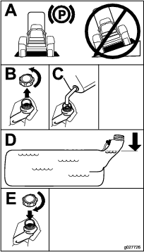
Filling the Fuel Tank
-
Park the machine on a level surface.
-
Engage the parking brake.
-
Shut off the engine and remove the key.
-
Clean around the fuel-tank cap.
-
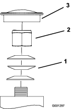
Fill the fuel tank to the bottom of the filler neck (Figure 7).
Note: Do not fill the fuel tank completely full. The empty space in the tank allows the fuel to expand.
Performing Daily Maintenance
Before starting the machine each day, perform the Each Use/Daily procedures listed in .
Breaking in a New Machine
New engines take time to develop full power. Mower decks and drive systems have higher friction when new, placing additional load on the engine. Allow 40 to 50 hours of break-in time for new machines to develop full power and best performance.
Using the Rollover-Protection System (ROPS)
Warning
To avoid injury or death from rollover, keep the roll bar in the fully raised, locked position and use the seat belt.
Ensure that the seat is secured to the machine.
Warning
There is no rollover protection when the roll bar is in the down position.
-
Lower the roll bar only when absolutely necessary.
-
Do not wear the seat belt when the roll bar is in the down position.
-
Drive slowly and carefully.
-
Raise the roll bar as soon as clearance permits.
-
Check carefully for overhead clearances (i.e., branches, doorways, electrical wires) before driving under any objects and do not contact them.
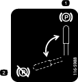
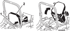
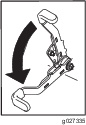
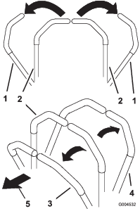
Lowering the Roll Bar
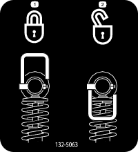
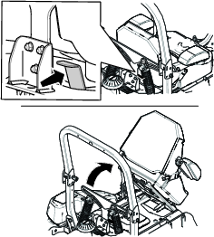
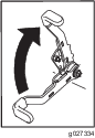
Raising the Roll Bar
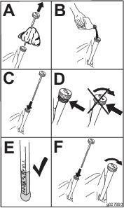
Important: Always use the seat belt with the roll bar in the raised position.
-
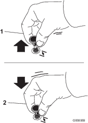
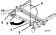
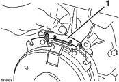
Raise the roll bar to the operating position and rotate the knobs until they move partially into the grooves (Figure 8).
-
Raise the roll bar to the full upright position while pushing on the upper roll bar so that the pins snap into position when the holes align with the pins (Figure 8).
-
Push on the roll bar and ensure that both pins are engaged.
Using the Safety-Interlock System
Warning
If the safety-interlock switches are disconnected or damaged, the machine could operate unexpectedly, causing personal injury.
-
Do not tamper with the interlock switches.
-
Check the operation of the interlock switches daily and replace any damaged switches before operating the machine.
Understanding the Safety-Interlock System
The safety-interlock system is designed to prevent the engine from starting unless:
-
The parking brake is engaged.
-
The blade-control switch (PTO) is disengaged.
-
The motion-control levers are in the NEUTRAL-LOCK position.
The safety-interlock system also is designed to shut off the engine when the motion-control levers are moved from the NEUTRAL-LOCK position with the parking brake engaged or if you rise from the seat when the PTO is engaged.
The hour meter has symbols to notify the user when the interlock component is in the correct position. When the component is in the correct position, a triangle lights up in the corresponding square.
Testing the Safety-Interlock System
Test the safety-interlock system before you use the machine each time. If the safety system does not operate as described below, have an Authorized Service Dealer repair the safety system immediately.
-
Sit on the seat, engage the parking brake, and move the blade-control switch (PTO) to the ON position. Try starting the engine; the engine should not start.
-
Sit on the seat, engage the parking brake, and move the blade-control switch (PTO) to the OFF position. Move either motion-control lever out of the NEUTRAL-LOCK position. Try starting the engine; the engine should not start. Repeat for the other control lever.
-
Sit on the seat, engage the parking brake, move the blade-control switch (PTO) to the OFF position, and move the motion-control levers to the NEUTRAL-LOCK position. Now start the engine. While the engine is running, disengage the parking brake, engage the blade-control switch (PTO), and rise slightly from the seat; the engine should shut off.
-
Sit on the seat, engage the parking brake, move the blade-control switch (PTO) to the OFF position, and move the motion-control levers to the NEUTRAL-LOCK position. Now start the engine. While the engine is running, center either motion control and move (forward or reverse); the engine should shut off. Repeat for other motion control.
-
Sit on the seat, disengage the parking brake, move the blade-control switch (PTO) to the OFF position, and move the motion-control levers to the NEUTRAL-LOCK position. Try starting the engine; the engine should not start.
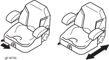
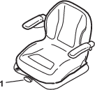
Positioning the Seat
The seat can move forward and backward. Position the seat where you have the best control of the machine and are most comfortable (Figure 10).
Unlatching the Seat
Machines with MyRide™ Suspension System
Machines without MyRide™ Suspension System
To unlatch the seat, push the seat latch forward (Figure 12).
Changing the Seat Suspension
Machines without MyRide™ Suspension System Only
The seat is adjustable to provide a smooth and comfortable ride. Position the seat where you are most comfortable.
To adjust it, turn the knob in front either direction to provide the best comfort (Figure 13).
Adjusting the MyRide™ Suspension System
Machines with MyRide™ Suspension System Only
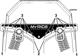

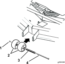
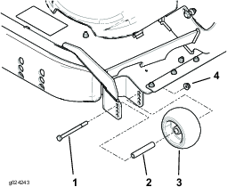
The MyRide™ suspension system adjusts to provide a smooth and comfortable ride. You can adjust the rear 2-shock assemblies to quickly and easily change the suspension system. Position the suspension system where you are most comfortable.
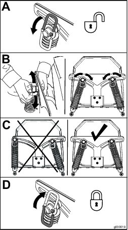
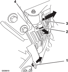
Adjusting the Rear-Shock Assemblies
The slots for the rear-shock assemblies have detent positions for reference. You can position the rear-shock assemblies anywhere in the slot, not just in the detent positions.
The following graphic shows the position for a soft or firm ride and the different detent positions (Figure 14).
Note: Ensure that the left and right rear-shock assemblies are always adjusted to the same positions.
Adjust the rear-shock assemblies (Figure 15).
During Operation
During Operation Safety
General Safety
-
The owner/operator can prevent and is responsible for accidents that may cause personal injury or property damage.
-
Wear appropriate clothing, including eye protection; long pants; slip-resistant, substantial footwear; and hearing protection. Tie back long hair and do not wear loose jewelry.
-
Use your full attention while operating the machine. Do not engage in any activity that causes distractions; otherwise, injury or property damage may occur.
-
Do not operate the machine while ill, tired, or under the influence of alcohol or drugs.
-
Never carry passengers on the machine and keep bystanders and pets away from the machine during operation.
-
Operate the machine only in good visibility to avoid holes or hidden hazards.
-
Avoid mowing on wet grass. Reduced traction could cause the machine to slide.
-
Ensure that all drives are in neutral, the parking brake is engaged, and you are in the operating position before you start the engine.
-
Keep your hands and feet away from the cutting units. Keep clear of the discharge opening at all times.
-
Look behind and down before backing up to be sure of a clear path.
-
Use care when approaching blind corners, shrubs, trees, or other objects that may obscure your vision.
-
Do not mow near drop-offs, ditches, or embankments. The machine could suddenly roll over if a wheel goes over the edge or if the edge gives way.
-
Stop the blades whenever you are not mowing.
-
Stop the machine, shut off the engine, remove the key, and inspect the blades after striking an object or if there is an abnormal vibration in the machine. Make all necessary repairs before resuming operation.
-
Slow down and use caution when making turns and crossing roads and sidewalks with the machine. Always yield the right-of-way.
-
Disengage the drive to the cutting unit, shut off the engine, and remove the key before adjusting the height of cut (unless you can adjust it from the operating position).
-
Never run an engine in an area where exhaust gases are enclosed.
-
Never leave a running machine unattended.
-
Before leaving the operating position (including to empty the catchers or to unclog the chute), do the following:
-
Stop the machine on level ground.
-
Disengage the power takeoff and lower the attachments.
-
Engage the parking brake.
-
Shut off the engine and remove the key.
-
Wait for all moving parts to stop.
-
-
Do not operate the machine when there is the risk of lightning.
-
Do not use the machine as a towing vehicle unless it has a hitch installed.
-
Do not change the governor speed or overspeed the engine.
-
Use only accessories and attachments approved by Toro.
-
This machine produces sound levels in excess of 85 dBA at the operator’s ear and can cause hearing loss through extended periods of exposure.

Rollover Protection System (ROPS) Safety
-
Do not remove the roll bar from the machine.
-
Ensure that the seat belt is attached and that you can release it quickly in an emergency.
-
Always wear your seat belt when the roll bar is up.
-
Check carefully for overhead obstructions and do not contact them.
-
Keep the roll bar in safe operating condition by thoroughly inspecting it periodically for damage and keeping all the mounting fasteners tight.
-
Replace a damaged roll bar. Do not repair or alter it.
Slope Safety
-
Slopes are a major factor related to loss of control and rollover accidents, which can result in severe injury or death. The operator is responsible for safe slope operation. Operating the machine on any slope requires extra caution. Before using the machine on a slope, do the following:
-
Review and understand the slope instructions in the manual and on the machine.
-
Use an angle indicator to determine the approximate slope angle of the area.
-
Never operate on slopes greater than 15 degrees.
-
Evaluate the site conditions of the day to determine if the slope is safe for machine operation. Use common sense and good judgment when performing this evaluation. Changes in the terrain, such as moisture, can quickly affect the operation of the machine on a slope.
-
-
Identify hazards at the base of the slope. Do not operate the machine near drop-offs, ditches, embankments, water, or other hazards. The machine could suddenly roll over if a wheel goes over the edge or the edge collapses. Keep a safe distance (twice the width of the machine) between the machine and any hazard. Use a walk-behind machine or a hand trimmer to mow the grass in these areas.
-
Avoid starting, stopping, or turning the machine on slopes. Avoid making sudden changes in speed or direction; turn slowly and gradually.
-
Do not operate a machine under any conditions where traction, steering, or stability is in question. Be aware that operating the machine on wet grass, across slopes, or downhill may cause the machine to lose traction. Loss of traction to the drive wheels may result in sliding and a loss of braking and steering. The machine can slide even if the drive wheels are stopped.
-
Remove or mark obstacles such as ditches, holes, ruts, bumps, rocks, or other hidden hazards. Tall grass can hide obstacles. Uneven terrain could overturn the machine.
-
Use extra care while operating with accessories or attachments, such as grass-collection systems. These can change the stability of the machine and cause a loss of control. Follow directions for counterweights.
-
If possible, keep the deck lowered to the ground while operating on slopes. Raising the deck while operating on slopes can cause the machine to become unstable.
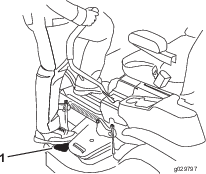
Entering the Operator’s Position
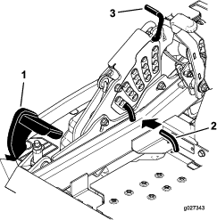
Use the mower deck as a step to get into the operator’s position (Figure 18).
Operating the Parking Brake
Always engage the parking brake when you stop the machine or leave it unattended.
Engaging the Parking Brake
Park the machine on a level surface.
Disengaging the Parking Brake
Operating the Mower Blade-Control Switch (PTO)
The blade-control switch (PTO) starts and stops the mower blades and any powered attachments.
Engaging the Blade-Control Switch (PTO)
Note: Engaging the blade-control switch (PTO) with the throttle position at half or less causes excessive wear to the drive belts.

Disengaging the Blade-Control Switch (PTO)
Operating the Throttle
You can move the throttle control between FAST and SLOW positions (Figure 23).
Always use the FAST position when engaging the PTO.

Operating the Choke
Starting the Engine
Important: Do not engage starter for more than 5 seconds at a time. If the engine fails to start, wait 15 seconds between attempts. Failure to follow these instructions can burn out the starter motor.
Note: You may need multiple attempts to start the engine the first time after adding fuel to an empty fuel system.
Shutting Off the Engine
Caution
Children or bystanders may be injured if they move or attempt to operate the machine while it is unattended.
Always remove the key and engage the parking brake when leaving the machine unattended.
Important: Make sure that the fuel-shutoff valve is closed before transporting or storing the machine, as fuel leakage may occur. Engage the parking brake before transporting. Make sure that you remove the key as the fuel pump may run and cause the battery to lose charge.
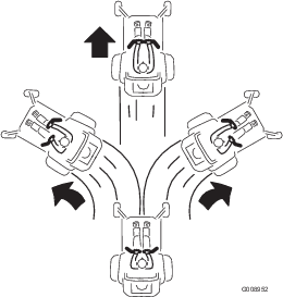
Using the Motion-Control Levers
Driving the Machine
The drive wheels turn independently, powered by hydraulic motors on each axle. You can turn 1 side in reverse while you turn the other forward, causing the machine to spin rather than turn. This greatly improves the machine maneuverability but may require some time for you to adapt to how it moves.
The throttle control regulates the engine speed as measured in rpm (revolutions per minute). Place the throttle control in the FAST position for best performance. Always operate in the full throttle position when mowing.
Warning
The machine can spin very rapidly. You may lose control of the machine and cause personal injury or damage to the machine.
-
Use caution when making turns.
-
Slow the machine down before making sharp turns.
Driving Forward
Note: The engine shuts off when you move the traction-control with the parking brake engaged.
To stop the machine, pull the motion-control levers to the NEUTRAL position.
-
Disengage the parking brake; refer to Disengaging the Parking Brake.
-
Move the levers to the center, unlocked position.
-
To go forward, slowly push the motion-control levers forward (Figure 28).
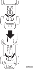
Driving Backward
-
Move the levers to the center, unlocked position.
-
To go backward, slowly pull the motion-control levers rearward (Figure 29).
Using the Side Discharge
Machines with Side Discharge Only
The mower has a hinged grass deflector that disperses clippings to the side and down toward the turf.
Danger
Without a grass deflector, discharge cover, or a complete grass-catcher assembly mounted in place, you and others are exposed to blade contact and thrown debris. Contact with rotating mower blade(s) and thrown debris will cause injury or death.
-
Never remove the grass deflector from the mower deck because the grass deflector routes material down toward the turf. If the grass deflector is ever damaged, replace it immediately.
-
Never put your hands or feet under the mower deck.
-
Never try to clear the discharge area or mower blades unless you move the blade-control switch (PTO) to the OFF position, rotate the key switch to the OFF position, and remove the key from the key switch.
-
Make sure that the grass deflector is in the down position.
Adjusting the Height of Cut
Using the Transport Lock
The transport lock has 2 positions, and is used with the deck-lift pedal. There is a LOCK position and an UNLOCK position for the transport position of the mower deck (Figure 30).
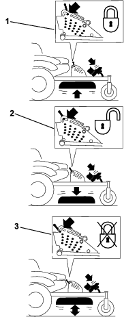
Adjusting the Height-of-Cut Pin
The height-of-cut is adjusted from 25 to 140 mm (1 to 5-1/2 inches) in 6 mm (1/4 inch) increments by relocating the clevis pin into different hole locations.
-
Move the transport lock to the lock position.
-
Push on the deck-lift pedal with your foot, and raise the mower deck to the transport position (also the 140 mm (5-1/2 inch) cutting height position) as shown in Figure 31.
-
To adjust, rotate the pin 90 degrees and remove the pin from the height-of-cut bracket (Figure 31).
-
Select a hole in the height-of-cut bracket corresponding to the height-of-cut desired, and insert the pin (Figure 31).
-
Push on the deck lift, pull back on the transport lock, and slowly lower the mower deck.
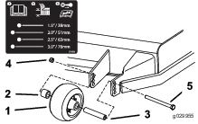
Adjusting the Anti-Scalp Rollers
For Machines with Side Discharge
Whenever you change the height-of-cut, adjust the height of the anti-scalp rollers.
Adjusting the Anti-Scalp Rollers
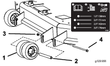
For Machines with Rear Discharge
Whenever you change the height of cut, it is recommended to adjust the height of the anti-scalp rollers.
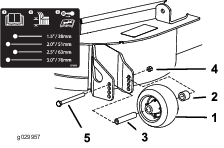
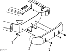
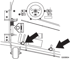
Adjusting the Skid(s)
For Machines with Rear Discharge
Mount the skids in the lower position when operating in height of cuts higher than 64 mm (2-1/2 inches) and in the higher position when operating in height of cuts lower than 64 mm (2-1/2 inches).
Note: When the skids become worn, switch the skid to the opposite sides of the mower, flipping them over. This allows you to use the skids longer before replacing them.
-
Park the machine on a level surface, disengage the blade-control switch, and engage the parking brake.
-
Shut off the engine, remove the key, and wait for all moving parts to stop before leaving the operating position.
-
Remove the carriage bolts and nuts from each skid (Figure 37).
-
Move each skid to the desired position and secure them with the carriage bolts and nuts.
Note: Only use the top or center sets of holes to adjust the skids. The bottom holes are used when switching sides on the mower deck, at which time they become the top holes on the other side of the mower.
-
To prevent damaging the skid, torque the carriage bolts and nuts for each skid to 12.4 to 14.7 N∙m (110 to 130 in-lb).
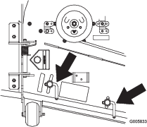
Adjusting the Flow Baffle Cam Locks
For Machines with Side Discharge
This procedure is applicable only to machines with the flow-baffle locks. Certain models have nuts and bolts in place of the flow-baffle locks and can be adjusted the same.
You can adjust the mower-discharge flow for different types of mowing conditions. Position the cam locks and baffle to give the best quality of cut.
-
Park the machine on a level surface, disengage the blade-control switch, and engage the parking brake.
-
Shut off the engine, remove the key, and wait for all moving parts to stop before leaving the operating position.
-
To adjust the cam locks, swing the lever up to loosen the cam lock (Figure 38).
-
Adjust the baffle and cam locks in the slots to the desired discharge flow.
-
Swing the lever back over to tighten the baffle and cam locks (Figure 38).
-
If the cam locks do not lock the baffle into place or it is too tight, loosen the lever and then rotate the cam lock.
Note: Adjust the cam lock until the desired locking pressure is achieved.
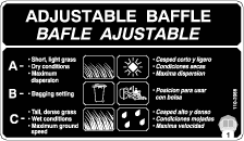
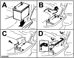
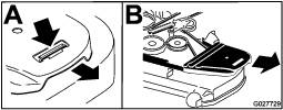
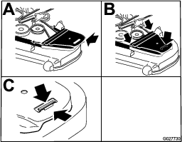
Positioning the Flow Baffle
For Machines with Side Discharge
The following figures are only recommendations for use. Adjustments vary by grass type, moisture content, and the height of the grass.
Note: If the engine power draws down and the mower ground speed is the same, open up the baffle.
Position A
This is the full rear position. The suggested use for this position is as follows:
-
Short, light grass mowing conditions
-
Dry conditions
-
Smaller grass clippings
-
Propels grass clippings farther away from the mower
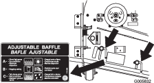
Position B
Use this position when bagging. Always align it with the blower opening.
Position C
This is the full open position. The suggested use for this position is as follows:
-
Tall, dense grass mowing conditions
-
Wet conditions
-
Lowers the engine-power consumption
-
Allows increased ground speed in heavy conditions
Operating Tips
Using the Fast Throttle Setting
For best mowing and maximum air circulation, operate the engine at the FAST position. Air is required to thoroughly cut grass clippings, so do not set the height-of-cut so low as to totally surround the mower deck in uncut grass. Always try to have 1 side of the mower deck free from uncut grass, which allows air to be drawn into the mower deck.
Cutting a Lawn for the First Time
Cut grass slightly longer than normal to ensure that the cutting height of the mower deck does not scalp any uneven ground. However, the cutting height used in the past is generally the best one to use. When cutting grass longer than 15 cm (6 inches) tall, you may want to cut the lawn twice to ensure an acceptable quality of cut.
Cutting a Third of the Grass Blade
It is best to cut only about a third of the grass blade. Cutting more than that is not recommended unless grass is sparse, or it is late fall when grass grows more slowly.
Alternating the Mowing Direction
Alternate the mowing direction to keep the grass standing straight. This also helps disperse clippings, which enhances decomposition and fertilization.
Mowing at Correct Intervals
Grass grows at different rates at different times of the year. To maintain the same cutting height, mow more often in early spring. As the grass growth rate slows in mid summer, mow less frequently. If you cannot mow for an extended period, first mow at a high cutting height, then mow again 2 days later at a lower height setting.
Using a Slower Cutting Speed
To improve cut quality, use a slower ground speed in certain conditions.
Avoiding Cutting Too Low
When mowing uneven turf, raise the cutting height to avoid scalping the turf.
Stopping the Machine
If you must stop the forward motion of the machine while mowing, a clump of grass clippings may drop onto your lawn. To avoid this, move onto a previously cut area with the blades engaged or you can disengage the mower deck while moving forward.
Keeping the Underside of the Mower Deck Clean
Clean clippings and dirt from the underside of the mower deck after each use. If grass and dirt build up inside the mower deck, cutting quality will eventually become unsatisfactory.
Maintaining the Blade(s)
Maintain a sharp blade throughout the cutting season because a sharp blade cuts cleanly without tearing or shredding the grass blades. Tearing and shredding turns grass brown at the edges, which slows growth and increases the chance of disease. Check the mower blades after each use for sharpness, and for any wear or damage. File down any nicks and sharpen the blades as necessary. If a blade is damaged or worn, replace it immediately with a genuine Toro replacement blade.
After Operation
After Operation Safety
General Safety
-
Clean grass and debris from the cutting units, mufflers, and engine compartment to help prevent fires. Clean up oil or fuel spills.
-
Shut off the fuel and remove the key before storing or transporting the machine.
-
Disengage the drive to the attachment whenever you are transporting or not using the machine.
-
Allow the engine to cool before storing the machine in any enclosure.
-
Never store the machine or fuel container where there is an open flame, spark, or pilot light, such as on a water heater or on other appliances.
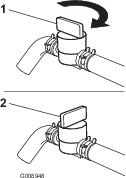
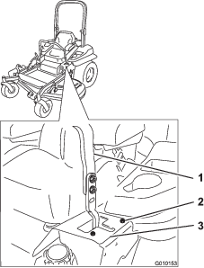
Using the Fuel-Shutoff Valve
The fuel-shutoff valve is located under the seat. Move the seat forward to access it.
Close the fuel-shutoff valve for transport, maintenance, and storage.
Ensure that the fuel-shutoff valve is open when starting the engine.
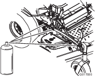
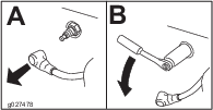
Using the Drive-Wheel-Release Valves
Warning
Hands may become entangled in the rotating drive components below the engine deck, which could result in serious injury.
Shut off the engine, remove the key, and allow all moving parts to stop before accessing the drive-wheel-release valves.
Warning
The engine and hydraulic-drive units can become very hot. Touching a hot engine or hydraulic-drive units can cause severe burns.
Allow the engine and hydraulic-drive units to cool completely before accessing the drive-wheel-release valves.
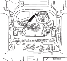
The drive-wheel-release valves are located in the back of each hydraulic-drive unit, under the seat.
Note: Make sure that the release valves are in the fully horizontal position when operating the machine; otherwise, severe damage to the hydraulic system can occur.
-
Park the machine on a level surface, disengage the blade-control switch, and engage the parking brake.
-
Shut off the engine, remove the key, and wait for all moving parts to stop before leaving the operating position.
-
Rotate the release-valve levers vertically to push the machine (Figure 43).
Note: This allows hydraulic fluid to bypass the pump, enabling the wheels to turn.
-
Disengage the parking brake before pushing the machine.
-
Rotate the release valve levers horizontally to run the machine (Figure 43).
Transporting the Machine
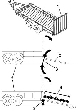
Use a heavy-duty trailer or truck to transport the machine. Use a full-width ramp. Ensure that the trailer or truck has all the necessary brakes, lighting, and marking as required by law. Please carefully read all the safety instructions. Knowing this information could help you or bystanders avoid injury. Refer to your local ordinances for trailer and tie-down requirements.
Warning
Driving on the street or roadway without turn signals, lights, reflective markings, or a slow-moving-vehicle emblem is dangerous and can lead to accidents, causing personal injury.
Do not drive the machine on a public street or roadway.
Selecting a Trailer
Warning
Loading a machine onto a trailer or truck increases the possibility of tip-over and could cause serious injury or death (Figure 44).
-
Use only a full-width ramp; do not use individual ramps for each side of the machine.
-
Do not exceed a 15-degree angle between the ramp and the ground or between the ramp and the trailer or truck.
-
Ensure that the length of ramp is at least 4 times as long as the height of the trailer or truck bed to the ground. This ensures that ramp angle does not exceed 15 degrees on flat ground.
Loading the Machine
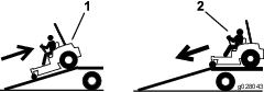
Warning
Loading a machine onto a trailer or truck increases the possibility of tip-over and could cause serious injury or death.
-
Use extreme caution when operating a machine on a ramp.
-
Back the machine up the ramp and drive it forward down the ramp.
-
Avoid sudden acceleration or deceleration while driving the machine on a ramp as this could cause a loss of control or a tip-over situation.
-
If using a trailer, connect it to the towing vehicle and connect the safety chains.
-
If applicable, connect the trailer brakes and lights.
-
Lower the ramp, ensuring that the angle between the ramp and the ground does not exceed 15 degrees (Figure 44).
-
Back the machine up the ramp (Figure 45).
-
Shut off the engine, remove the key, and engage the parking brake.
-
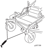
Tie down the machine near the front caster wheels and the rear bumper with straps, chains, cable, or ropes (Figure 46). Refer to local regulations for tie-down requirements.
Using the Z Stand
The Z Stand raises the front end of the machine to allow you to clean the mower and remove the blades.
Warning
The machine could fall onto someone and cause serious injury or death.
-
Use extreme caution when operating the machine on the Z Stand.
-
Use the Z Stand only for cleaning the mower and removing the blades.
-
Do not keep the machine on the Z Stand for extended periods of time.
-
Always shut off the engine, set the parking brake, and remove the key before performing any maintenance to the mower.
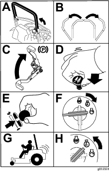
Driving up onto the Z Stand
Important: Use the Z Stand on a level surface.
-
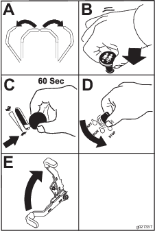
Raise the mower deck to the transport position.
-
Remove the bracket pin (Figure 47).
-
Raise the latch.
-
Swing the stand foot out front and slide it toward machine, into the bottom of slot (Figure 47 and Figure 48).
-
Set the foot of the stand on the ground and rest the latch on the pivot tab (Figure 48).
-
Start the engine and put it at half throttle.
Note: For best results, place the foot of the stand into the seams in sidewalks or into the turf (Figure 48).
-
Drive the machine onto the stand. Stop when the latch drops over the tab into the locked position (Figure 48).
-
Engage the parking brake and turn off the engine.
-
Chock or block the drive wheels.
Warning
The parking brake may not hold the machine parked on the Z Stand and could cause personal injury or property damage.
Do not park on the Z Stand unless the wheels are chocked or blocked.
-
Perform the maintenance.
Maintenance
Recommended Maintenance Schedule(s)
| Maintenance Service Interval | Maintenance Procedure |
|---|---|
| After the first 8 hours |
|
| After the first 100 hours |
|
| After the first 250 hours |
|
| Before each use or daily |
|
| Every 50 hours |
|
| Every 100 hours |
|
| Every 200 hours |
|
| Every 250 hours |
|
| Every 500 hours |
|
| Monthly |
|
| Yearly |
|
| Yearly or before storage |
|
Important: Refer to your engine owner's manual for additional maintenance procedures.
Caution
If you leave the key in the switch, someone could accidently start the engine and seriously injure you or other bystanders.
Remove the key from the switch before you perform any maintenance.
Pre-Maintenance Procedures
Maintenance Safety
-
Before repairing the machine do the following:
-
Disengage the drives.
-
Engage the parking brake.
-
Shut off the engine and remove the key.
-
Disconnect the spark-plug wire.
-
-
Park the machine on a level surface.
-
Clean grass and debris from the cutting unit, drives, mufflers, and engine to help prevent fires.
-
Clean up oil or fuel spills.
-
Do not allow untrained personnel to service the machine.
-
Use jack stands to support the machine and/or components when required.
-
Carefully release pressure from components with stored energy.
-
Disconnect the battery or remove the spark-plug wire before making any repairs. Disconnect the negative terminal first and the positive terminal last. Connect the positive terminal first and negative last.
-
Use care when checking the blades. Wrap the blade(s) or wear thickly padded gloves, and use caution when servicing them. Only replace blades; do not straighten or weld them.
-
Keep your hands and feet away from moving parts. If possible, do not make adjustments with the engine running.
-
Keep all parts in good working condition and all hardware tightened, especially the blade-attachment bolts. Replace all worn or damaged decals.
-
Never interfere with the intended function of a safety device or reduce the protection provided by a safety device. Check their proper operation regularly.
-
Check the parking brake operation frequently. Adjust and service as required.
Releasing the Mower-Deck Curtain
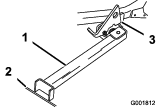
Loosen the bottom bolt of the curtain to release the mower-deck curtain and access the top of the mower deck (Figure 50). Tighten the bolt after maintenance to install the curtain.
Removing the Sheet-Metal Guard
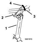
Loosen the 2 front bolts and remove the sheet-metal guard to access the mower belts and spindles (Figure 51). Install the sheet-metal guard and tighten the bolts after maintenance.
Lubrication
Greasing the Machine
Grease more frequently when operating conditions are extremely dusty or sandy.
Grease Type: No. 2 lithium or molybdenum grease
-
Park the machine on a level surface, disengage the blade-control switch, and engage the parking brake.
-
Shut off the engine, remove the key, and wait for all moving parts to stop before leaving the operating position.
-
Clean the grease fittings with a rag.
Note: Make sure that you scrape any paint off the front of the fitting(s).
-
Connect a grease gun to the fitting.
-
Pump grease into the fittings until grease begins to ooze out of the bearings.
-
Wipe up any excess grease.
Adding Light Oil or Spray Lubrication
| Maintenance Service Interval | Maintenance Procedure |
|---|---|
| Every 100 hours |
|
Lubricate the deck-lift pivots.
Greasing the Mower Deck
| Maintenance Service Interval | Maintenance Procedure |
|---|---|
| Yearly |
|
-
Park the machine on a level surface, disengage the blade-control switch, and engage the parking brake.
-
Shut off the engine, remove the key, and wait for all moving parts to stop before leaving the operating position.
-
Loosen the bottom bolt holding the mower-deck curtain to the mower deck. Refer to Releasing the Mower-Deck Curtain.
-
Remove the sheet-metal guard. Refer to Removing the Sheet-Metal Guard.
-
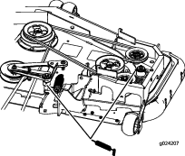
Grease the mower deck idler-pulley pivot until grease comes out the bottom (Figure 53 or Figure 54).
-
Grease the drive-belt idler arms (Figure 55).
-
Grease the deck-belt idler arms (rear discharge machines only) as shown in Figure 56.
-
Install the sheet-metal guard. Refer to Releasing the Mower-Deck Curtain.
-
Tighten the bolt for the mower-deck curtain. Refer to Releasing the Mower-Deck Curtain.
-
Remove the dust cap and adjust the caster pivots.
Note: Keep the dust cap off until greasing is done.
-
Remove the hex plug.
-
Thread a grease fitting into the hole.
-
Pump grease into the fitting until it oozes out around the top bearing.
-
Remove the grease fitting in the hole.
-
Install the hex plug and dust cap (Figure 57).
-
Grease the caster-wheel bearings (Figure 57).
Lubricating the Caster-Wheel Hubs
| Maintenance Service Interval | Maintenance Procedure |
|---|---|
| Yearly |
|
-
Park the machine on a level surface, disengage the blade-control switch, and engage the parking brake.
-
Shut off the engine, remove the key, and wait for all moving parts to stop before leaving the operating position.
-
Raise the mower for access.
-
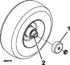
Remove the caster wheel from the caster forks.
-
Remove the seal guards from the wheel hub.
-
Remove a spacer nut from the axle assembly in the caster wheel.
Note: Thread-locking adhesive has been applied to lock the spacer nuts to the axle.
-
Remove the axle (with the other spacer nut still assembled to it) from the wheel assembly.
-
Pry out seals and inspect bearings for wear or damage and replace if necessary.
-
Pack the bearings with a general-purpose grease.
-
Insert 1 bearing and 1 new seal into the wheel.
Note: Replace the seals.
-
If the axle assembly is missing both spacer nuts, apply a thread-locking adhesive to 1 spacer nut and thread it onto the axle with the wrench flats facing outward.
Note: Do not thread the spacer nut all of the way onto the end of the axle. Leave approximately 3 mm (1/8 inch) from the outer surface of the spacer nut to the end of the axle inside the nut.
-
Insert the assembled nut and axle into the wheel on the side of the wheel with the new seal and bearing.
-
With the open end of the wheel facing up, fill the area inside the wheel around the axle full of general-purpose grease.
-
Insert the second bearing and new seal into the wheel.
-
Apply a thread-locking adhesive to the second spacer nut, and thread it onto the axle with the wrench flats facing outward.
-
Torque the nut to 8 to 9 N∙m (75 to 80 in-lb), loosen, then torque to 2 to 3 N∙m (20 to 25 in-lb).
Note: Make sure that the axle does not extend beyond either nut.
-
Install the seal guards over the wheel hub, and insert the wheel into the caster fork.
-
Install the caster bolt and tighten the nut fully.
Important: To prevent seal and bearing damage, check the bearing adjustment often. Spin the caster tire. The tire should not spin freely (more than 1 or 2 revolutions) or have any side play. If the wheel spins freely, adjust the torque on the spacer nut until there is a slight amount of drag. Apply another layer of thread-locking adhesive.
Engine Maintenance
Engine Safety
-
Shut off the engine before checking the oil or adding oil to the crankcase.
-
Keep your hands, feet, face, clothing, and other body parts away the muffler and other hot surfaces.
Servicing the Air Cleaner
| Maintenance Service Interval | Maintenance Procedure |
|---|---|
| Every 250 hours |
|
| Every 500 hours |
|
Note: Check the filters more frequently if the operating conditions are extremely dusty or sandy.
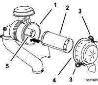
Removing the Filters
-
Park the machine on a level surface, disengage the blade-control switch (PTO), and engage the parking brake.
-
Shut off the engine, remove the key, and wait for all moving parts to stop before leaving the operating position.
-
Release the latches on the air cleaner and pull the air-cleaner cover off the air-cleaner body (Figure 59).
-
Clean the inside of the air-cleaner cover with compressed air.
-
Gently slide the primary filter out of the air-cleaner body (Figure 59).
Note: Avoid knocking the filter into the side of the body.
-
Remove the safety filter only to replace it.
Important: Do not attempt to clean the safety filter. If the safety filter is dirty, then the primary filter is damaged. Replace both filters.
-
Inspect the primary filter for damage by looking into the filter while shining a bright light on the outside of the filter.
Note: Holes in the filter appear as bright spots. If the filter is damaged, discard it.
Inspecting the Filters
-
Inspect the safety filter. If it is dirty, replace both the safety and primary filters.
Important: Do not attempt to clean the safety filter. If the safety filter is dirty, then the primary filter is damaged.
-
Inspect the primary filter for damage by looking into the filter while shining a bright light on the outside of the filter. If the primary filter is dirty, bent, or damaged, replace it.
Note: Holes in the filter appear as bright spots. Do not clean the primary filter.
Installing the Filters
Important: To prevent engine damage, always operate the engine with both air filters and the cover installed.
-
If you are installing new filters, check each filter for shipping damage.
Note: Do not use a damaged filter.
-
If you are replacing the inner filter, carefully slide it into the filter body (Figure 59).
-
Carefully slide the primary filter over the safety filter (Figure 59).
Note: Ensure that the primary filter is fully seated by pushing on the outer rim while installing it.
Important: Do not press on the soft, inside area of the filter.
-
Install the air-cleaner cover and secure the latches (Figure 59).
Servicing the Engine Oil
Engine-Oil Specifications
Oil Type:: Detergent oil (API service SF, SG, SH, SJ or SL)
Engine Oil Capacity:
-
Model 74902TE, 74919TE, 75969TE: 2.0 L (68 fl oz) with the filter; 1.8 L (61 fl oz) without the filter
-
Model 74925TE, 74942TE: 2.3 L (78 fl oz) with a filter change; 2.1 L (71 fl oz) without a filter change
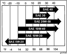
Viscosity: Refer to the table below.
Checking the Engine-Oil Level
| Maintenance Service Interval | Maintenance Procedure |
|---|---|
| Before each use or daily |
|
Note: Check the oil when the engine is cold.
Important: If you overfill or underfill the engine crankcase with oil and run the engine, you may damage the engine.
-
Park the machine on a level surface, disengage the blade-control switch (PTO), and engage the parking brake.
-
Shut off the engine, remove the key, and wait for all moving parts to stop before leaving the operating position.
Note: Ensure that the engine is cool so that the oil has had time to drain into the sump.
-
To keep dirt, grass clippings, etc., out of the engine, clean the area around the oil-fill cap and dipstick before removing it (Figure 61).
Changing the Engine Oil
| Maintenance Service Interval | Maintenance Procedure |
|---|---|
| After the first 8 hours |
|
| Every 100 hours |
|
-
Park the machine so that the drain side is slightly lower than the opposite side to ensure that the oil drains completely.
-
Disengage the blade-control switch (PTO) and engage the parking brake.
-
Shut off the engine, remove the key, and wait for all moving parts to stop before leaving the operating position.
-
Drain the oil from the engine (Figure 62).
-
Slowly pour approximately 80% of the specified oil into the filler tube and slowly add the additional oil to bring it to the Full mark (Figure 63).
-
Dispose of the used oil at a recycling center.
Changing the Engine-Oil Filter
| Maintenance Service Interval | Maintenance Procedure |
|---|---|
| Every 200 hours |
|
-
Drain the oil from the engine; refer to Changing the Engine Oil.
-
Change the engine-oil filter (Figure 64).

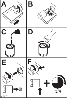
Note: Ensure that the oil-filter gasket touches the engine, and then turn the oil filter an extra 3/4 turn.
-
Fill the crankcase with the proper type of new oil; refer to Changing the Engine Oil.
Servicing the Spark Plug
| Maintenance Service Interval | Maintenance Procedure |
|---|---|
| Every 100 hours |
|
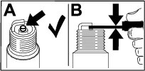
Ensure that the air gap between the center and side electrodes is correct before installing the spark plug. Use a spark plug wrench for removing and installing the spark plug and a gapping tool or feeler gauge to check and adjust the air gap. Install a new spark plug if necessary.
Type of Spark Plug: NGK® BPR4ES or equivalent
Air Gap: 0.75 mm (0.03 inch)
Removing the Spark Plug
-
Shut off the engine, remove the key, and wait for all moving parts to stop before leaving the operating position.
-
Disengage the PTO, move the motion-control levers to the NEUTRAL-LOCK position, and engage the parking brake.
-
Remove the left hydraulic-unit shroud in the order listed with Figure 65. This gives you access to the front spark plug.

-
Remove the spark plug.

-
Install the left hydraulic-unit shroud (Figure 65).
Checking the Spark Plug
Important: Do not clean the spark plug(s). Always replace the spark plug(s) when it has a black coating, worn electrodes, an oily film, or cracks.
If you see light brown or gray on the insulator, the engine is operating properly. A black coating on the insulator usually means the air cleaner is dirty.
Set the gap to 0.75 mm (0.03 inch).
Installing the Spark Plug
Checking the Spark Arrester
For Machines with a Spark Arrester
| Maintenance Service Interval | Maintenance Procedure |
|---|---|
| Every 50 hours |
|
Warning
Hot exhaust-system components may ignite fuel vapors even after you shut off the engine. Hot particles exhausted during engine operation may ignite flammable materials, resulting in personal injury or property damage.
Do not refuel or run the engine unless the spark arrester is installed.
-
Park the machine on a level surface, disengage the PTO, and engage the parking brake.
-
Shut off the engine, remove the key, and wait for all moving parts to stop before leaving the operating position.
-
Wait for the muffler to cool.
-
If you see any breaks in the screen or welds, replace the arrester.
-
If the screen is plugged, remove the arrester, shake loose particles out of the arrester, and clean the screen with a wire brush (soak the screen in solvent if necessary).
-
Install the arrester on the exhaust outlet.
Fuel System Maintenance
Replacing the Fuel Filter
| Maintenance Service Interval | Maintenance Procedure |
|---|---|
| Every 200 hours |
|
| Every 500 hours |
|
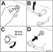
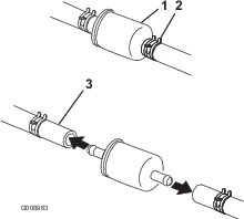
Important: Install the fuel line hoses and secure with plastic ties the same as they were originally installed at the factory to keep the fuel line away from components that can cause fuel line damage.
The fuel filter is located near the engine on the left front of the engine.
-
Park the machine on a level surface, disengage the blade-control switch (PTO), and engage the parking brake.
-
Shut off the engine, remove the key, and wait for all moving parts to stop before leaving the operating position.
-
Allow the machine to cool down.
-
Close the fuel-shutoff valve under the seat.
-
Replace the fuel filter (Figure 69).
-
Open the fuel-shutoff valve.
Servicing the Fuel Tank
Do not attempt to drain the fuel tank. Ensure that an Authorized Service Dealer drains the fuel tank and services any components of the fuel system.
Electrical System Maintenance
Electrical System Safety
-
Disconnect the battery before repairing the machine. Disconnect the negative terminal first and the positive last. Connect the positive terminal first and the negative last.
-
Charge the battery in an open, well-ventilated area, away from sparks and flames. Unplug the charger before connecting or disconnecting the battery. Wear protective clothing and use insulated tools.
Servicing the Battery
| Maintenance Service Interval | Maintenance Procedure |
|---|---|
| Monthly |
|
Removing the Battery
Warning
Battery terminals or metal tools could short against metal machine components causing sparks. Sparks can cause the battery gasses to explode, resulting in personal injury.
-
When removing or installing the battery, do not allow the battery terminals to touch any metal parts of the machine.
-
Do not allow metal tools to short between the battery terminals and metal parts of the machine.
Warning
Incorrectly removing the cables from battery could damage the machine and cables, causing sparks. Sparks can cause the battery gasses to explode, resulting in personal injury.
-
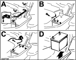
Always disconnect the negative (black) battery cable before disconnecting the positive (red) cable.
-
Always connect the positive (red) battery cable before connecting the negative (black) cable.
-
Park the machine on a level surface, disengage the blade-control switch (PTO), and engage the parking brake.
-
Shut off the engine, remove the key, and wait for all moving parts to stop before leaving the operating position.
-
Remove the battery as shown in Figure 70.
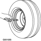
Charging the Battery
Warning
Charging the battery produces gasses that can explode.
Never smoke near the battery and keep sparks and flames away from the battery.
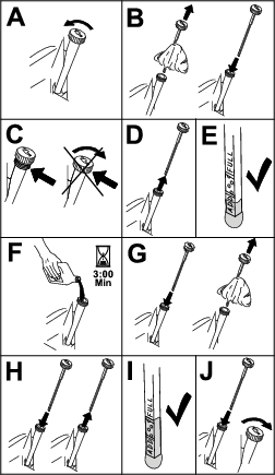
Important: Always keep the battery fully charged (1.265 specific gravity). This is especially important to prevent battery damage when the temperature is below 0°C (32°F).
-
Remove the battery from the chassis; refer to Removing the Battery.
-
Charge the battery for 10 to 15 minutes at 25 to 30 A or for 30 minutes at 10 A.
Note: Do not overcharge the battery.
-
When the battery is fully charged, unplug the charger from the electrical outlet, then disconnect the charger leads from the battery posts (Figure 71).
-
Install the battery in the machine and connect the battery cables; refer to Installing the Battery.
Note: Do not run the machine with the battery disconnected; electrical damage may occur.
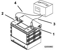
Installing the Battery
Note: Position the battery in the tray with the terminal posts opposite from the hydraulic tank (Figure 70).
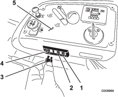
Servicing the Fuses
The electrical system is protected by fuses. It requires no maintenance, however, if a fuse blows check the component/circuit for a malfunction or short.
The fuses are located on the console to the right of the seat (Figure 73).
-
To replace the fuses, pull out on the fuse to remove it.
-
Install a new fuse (Figure 73).
Drive System Maintenance
Checking the Seat Belt
| Maintenance Service Interval | Maintenance Procedure |
|---|---|
| Before each use or daily |
|
Inspect the seat belt for wear, cuts, and proper operation of the retractor and buckle. Replace the seat belt if it is damaged.
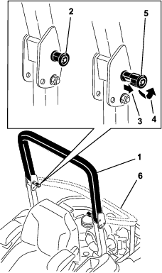
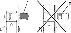
Checking the Roll-Bar Knobs
| Maintenance Service Interval | Maintenance Procedure |
|---|---|
| Before each use or daily |
|
Warning
To avoid injury or death from rollover, keep the roll bar in the fully raised, locked position and use the seat belt.
Ensure that the seat is secured to the machine.
-
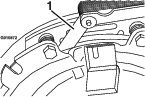
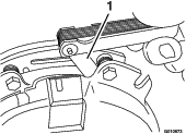
Check that both the mounting hardware and the knobs are in good working condition.
-
Make sure that the knobs are fully engaged with the roll bar in the raised position.
Note: The upper hoop of the roll bar may need to be pushed forward or pulled rearward to fully engage both knobs (Figure 74 and Figure 75).
Adjusting the Tracking
-
Disengage the blade-control switch (PTO).
-
Drive to an open flat area, move the motion-control levers to the NEUTRAL-LOCK position.
-
Move the throttle midway between fast and slow.
-
Move both motion-control levers all the way forward until they both hit the stops in the T-slot.
-
Check which way the machine tracks.
-
If it tracks to the right, loosen the bolts and adjust the left stop plate rearward on the left T-slot until the machine tracks straight (Figure 76).
-
If it tracks to the left, loosen the bolts and adjust the right stop plate rearward on the right T-slot until the machine tracks straight (Figure 76).
-
-
Tighten the stop plate (Figure 76).
Checking the Tire Pressure
| Maintenance Service Interval | Maintenance Procedure |
|---|---|
| Every 50 hours |
|
Maintain the air pressure in the front and rear tires at 90 kPa (13 psi). Uneven tire pressure can cause uneven cut. Check the tires when they are cold to get the most accurate pressure reading.
Checking the Wheel Lug Nuts
| Maintenance Service Interval | Maintenance Procedure |
|---|---|
| After the first 100 hours |
|
| Every 500 hours |
|
Check and torque the wheel lug nuts to 122 to 129 N∙m (90 to 95 ft-lb).
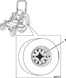
Checking the Wheel-Hub Slotted Nut
| Maintenance Service Interval | Maintenance Procedure |
|---|---|
| After the first 100 hours |
|
| Every 500 hours |
|
Check and ensure that the torque of the slotted nut is 286 to 352 N∙m (211 to 260 ft-lb).
Note: Do not use anti-seize compound on wheel hub.
Adjusting the Caster-Pivot Bearing
| Maintenance Service Interval | Maintenance Procedure |
|---|---|
| Every 500 hours |
|
-
Park the machine on a level surface, disengage the blade-control switch (PTO), and engage the parking brake.
-
Shut off the engine, remove the key, and wait for all moving parts to stop before leaving the operating position.
-
Remove the dust cap from caster and tighten the locknut (Figure 79).
-
Tighten the locknut until the spring washers are flat, and then back off a 1/4 turn to properly set the preload on the bearings (Figure 79).
Important: Make sure that the spring washers are installed correctly as shown in Figure 79.
-
Install the dust cap (Figure 79).
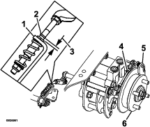
Using the Clutch Shim
Some later model year units have been built with clutches that contain a brake shim. When the clutch brake has worn to the point where the clutch no longer engages consistently, you can remove the shim to extend the clutch life.
Removing the Clutch Shim
-
Park the machine on a level surface, disengage the blade-control switch (PTO), and engage the parking brake.
-
Shut off the engine, remove the key, and wait for all moving parts to stop before leaving the operating position.
-
Using an air compressor, blow out any debris from under the brake pole and around the brake spacers (Figure 81).
-
Check the condition of the wire-harness leads, connectors, and terminals.
Note: Clean or repair as necessary.
-
Verify that 12 V is present at the clutch connector when the blade-control switch (PTO) switch is engaged.
-
Measure the gap between the rotor and armature. If the gap is greater than 1 mm (0.04 inch), do the following steps:
-
Loosen both brake-mounting bolts 1/2 to 1 full turn as shown in Figure 82.
Note: Do not remove the brake pole from the field shell/armature. The brake pole has worn to match the armature and needs to continue to match after you remove the shim to ensure proper brake torque.
-
Using needle-nose pliers, or by hand, hold the tab and remove the shim (Figure 83).
Note: Do not discard the shim until the clutch is functioning properly.
-
Using a pneumatic line, blow out any debris from under the brake pole and around the brake spacers.
-
Torque each bolt (M6 x 1) to 12.3 to 13.7 N∙m (9.5 to 10.5 ft-lb).
-
Using a 0.25 mm (0.01 inch) thick feeler gauge, verify that a gap is present between the rotor and the armature face on both sides of the brake pole as shown in Figure 84 and Figure 85.
Note: Due to the way the rotor and the armature faces wear (peaks and valleys) it is sometimes difficult to measure the gap accurately.
-
If the gap is less than 0.25 mm (0.01 inch), then install the shim; refer to Using the Clutch Shim.
-
If the gap is sufficient, proceed to the safety check in step 6.
-
-
Perform the following safety check:
-
Sit on the seat and start the engine.
-
Make sure that the blades do not engage with the blade-control switch (PTO) in the OFF position, and that the clutch is disengaged.
If the clutch does not disengage, install the shim again; refer to Using the Clutch Shim.
-
Engage and disengage the blade-control switch (PTO) 10 consecutive times to ensure that the clutch is functioning properly.
-
-
Cooling System Maintenance
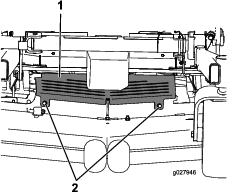
Cleaning the Engine Screen and Engine-Oil Cooler
| Maintenance Service Interval | Maintenance Procedure |
|---|---|
| Before each use or daily |
|
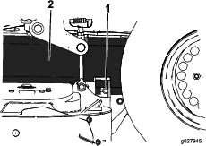
Remove any buildup of grass, dirt, or other debris from the oil cooler and the engine screen (Figure 86).

Remove any buildup of grass, dirt, or other debris from the engine screen. This helps ensure adequate cooling and correct engine speed and reduces the possibility of overheating and mechanical damage to the engine (Figure 83).
Cleaning the Engine-Cooling Fins and Shrouds
| Maintenance Service Interval | Maintenance Procedure |
|---|---|
| Every 100 hours |
|
-
Park the machine on a level surface, disengage the blade-control switch (PTO), and engage the parking brake.
-
Shut off the engine, remove the key, and wait for all moving parts to stop before leaving the operating position.
-
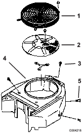
Remove the air-intake screen, the recoil starter, and the fan housing (Figure 87).
-
Clean the debris and grass from the engine parts.
-
Install the air-intake screen, the recoil starter, and the fan housing (Figure 87).
Checking and Cleaning the Hydraulic-Unit Shrouds
| Maintenance Service Interval | Maintenance Procedure |
|---|---|
| Before each use or daily |
|
-
Park the machine on a level surface, disengage the blade-control switch (PTO), and engage the parking brake.
-
Shut off the engine, remove the key, and wait for all moving parts to stop before leaving the operating position.
-
Move the seat forward.
-
Clean the debris and grass from the hydraulic-unit shrouds (Figure 88).
-
Position the seat.
Brake Maintenance
Adjusting the Parking Brake
| Maintenance Service Interval | Maintenance Procedure |
|---|---|
| After the first 100 hours |
|
| Every 500 hours |
|
Note: Perform this procedure at the recommended service interval or when a brake component has been removed or replaced.
-
Park the machine on a level surface, disengage the blade-control switch (PTO), and engage the parking brake.
-
Shut off the engine, remove the key, and wait for all moving parts to stop before leaving the operating position.
-
Raise the back of the machine and support the machine with jack stands.
Caution
Raising the machine for service or maintenance relying solely on mechanical or hydraulic jacks could be dangerous. The mechanical or hydraulic jacks may not be enough support or may malfunction allowing the machine to fall, which could cause injury.
Do not rely solely on mechanical or hydraulic jacks for support. Use adequate jack stands or equivalent support.
-
Remove the rear tires from the machine.
-
Remove any debris from the brake area.
-
Rotate the drive-wheel release handle to the released position; refer to Using the Drive-Wheel-Release Valves.
-
Check to see if there is a visible gap between the L-bracket and the linkage stop (Figure 89).
-
Disengage the parking brake, the lever should be in the down position.
-
Turn the wheel hub by hand in both directions relative to the caliper; the wheel hub should move freely between the caliper.
-
If a gap is needed or the wheel hub does not move freely:
-
Disengage the parking brake.
-
Disconnect and fine-tune the rear linkage assembly:
-
Shorten the link to create a gap.
-
Lengthen the link to allow wheel hub movement.
-
-
Connect the rear linkage assembly.
-
-
Engage the parking brake and check the gap.
-
Repeat steps 8 through 12 until a visible gap is achieved and the wheel hub rotates freely.
-
Repeat this procedure for the brake on the opposite side.
-
Rotate the drive-wheel release handle to the operating position; refer to Using the Drive-Wheel-Release Valves.
-
Install the rear tires and torque the lug nuts; refer to Checking the Wheel Lug Nuts.
-
Remove the jack stands.
Belt Maintenance
Inspecting the Belts
| Maintenance Service Interval | Maintenance Procedure |
|---|---|
| Every 50 hours |
|
Replace the belt if it is worn. The signs of a worn belt include squealing while the belt is rotating; the blades slipping while cutting grass; and frayed edges, burn marks, and cracks on the belt.
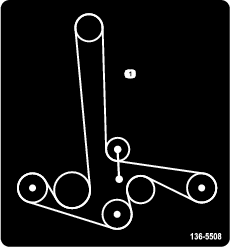
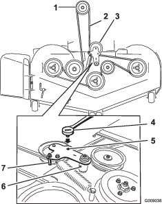
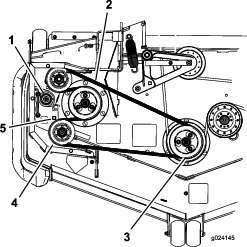
Replacing the Mower Belt for Side-Discharge Mower Decks
-
Park the machine on a level surface, disengage the blade-control switch (PTO), and engage the parking brake.
-
Shut off the engine, remove the key, and wait for all moving parts to stop before leaving the operating position.
-
Lower the mower to the 76 mm (3 inch) height-of-cut.
-
Loosen the bottom bolt holding the mower-deck curtain to the mower deck. Refer to Releasing the Mower-Deck Curtain.
-
Remove the sheet-metal guard. Refer to Removing the Sheet-Metal Guard.
-
Remove the belt covers (Figure 90).
-
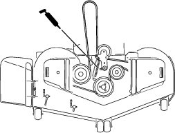
Use a ratchet in the square hole in the idler arm to remove tension on the idler spring (Figure 91).
-
Remove the belt from the mower-deck pulleys.
-
Remove the belt guide on the spring-loaded idler arm (Figure 91).
-
Remove the existing belt.
-
Install the new belt around the mower pulleys and the clutch pulley under the engine (Figure 91).
-
Install the belt guide on the idler arm (Figure 91).
-
Using the ratchet in the square hole, install the idler spring (Figure 91).
Note: Make sure that the spring ends are seated in the anchor grooves.
-
Install the belt covers (Figure 92).
-
Install the sheet-metal guard. Refer to Removing the Sheet-Metal Guard.
-
Tighten the bolt for the mower-deck curtain. Refer to Releasing the Mower-Deck Curtain.
Replacing the Mower Belt for Rear-Discharge Mower Decks
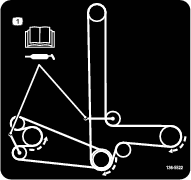
Replacing the Counter-Rotating Belt
-
Park the machine on a level surface, disengage the blade-control switch (PTO), and engage the parking brake.
-
Shut off the engine, remove the key, and wait for all moving parts to stop before leaving the operating position.
-
Lower the mower to the 76 mm (3 inches) height of cut.
-
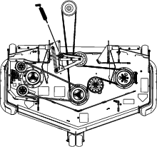
Lift the floor pan up to gain access to the center pulley.
-
Loosen the bottom bolt holding the mower-deck curtain to the mower deck. Refer to Releasing the Mower-Deck Curtain.
-
Remove the sheet-metal guard. Refer to Removing the Sheet-Metal Guard.
-
Remove the plastic belt cover (Figure 94).
-
Remove the 3 bolts holding the metal belt cover in place and remove the metal belt cover.
-
Use a ratchet in the square hole in the idler arm to remove tension on the idler spring (Figure 93).
-
Remove the belt from the mower deck pulley (Figure 93).
-
Remove the belt from the remaining pulleys (Figure 93).
-
Route the new belt abound the mower pulleys.
-
Using the ratchet in the square hole, remove the tension on the spring, and guide the new belt around the idler pulley (Figure 93).
Replacing the Mower Belt
-
Park the machine on a level surface, disengage the blade-control switch (PTO), and engage the parking brake.
-
Shut off the engine, remove the key, and wait for all moving parts to stop before leaving the operating position.
-
Lower the mower to the 76 mm (3 inches) height of cut.
-
Loosen the bottom bolt holding the mower-deck curtain to the mower deck. Refer to Releasing the Mower-Deck Curtain.
-
Remove the sheet-metal guard. Refer to Removing the Sheet-Metal Guard.
-
Remove the belt covers (Figure 94).
-
Remove the counter-rotating belt; refer to Replacing the Counter-Rotating Belt.
-
Use a ratchet in the square hole in the idler arm to remove tension on the idler spring (Figure 95).
-
Remove the belt from the mower-deck pulleys and the clutch pulley.
-
Install the new belt around the mower pulleys and the clutch pulley under the engine (Figure 95).
-
Rotate and ensure the belt-guide tab hits against the pivot hub (Figure 95).
-
Using the ratchet in the square hole, install the belt around the spring-loaded idler pulley (Figure 95). Seat the spring ends in the anchor grooves.
-
Install the belt covers (Figure 96).
-
Install the sheet-metal guard. Refer to Removing the Sheet-Metal Guard.
-
Tighten the bolt for the mower-deck curtain. Refer to Releasing the Mower-Deck Curtain.
Replacing the Hydraulic Pump-Drive Belt
-
Park the machine on a level surface, disengage the blade-control switch (PTO), and engage the parking brake.
-
Shut off the engine, remove the key, and wait for all moving parts to stop before leaving the operating position.
-
Remove the mower belt; refer to Replacing the Mower Belt for Side-Discharge Mower Decks or Replacing the Mower Belt for Rear-Discharge Mower Decks.
-
Raise the machine and support it with jack stands (Figure 97).
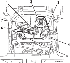
-
Use a ratchet in the square hole in the idler arm to remove the idler spring (Figure 97).
-
Unhook the idler spring from the frame (Figure 97).
-
Remove the belt from the hydraulic-unit-drive pulleys and the engine pulley.
-
Install the new belt around engine pulley and the 2 drive pulleys.
-
Using a ratchet in the square hole in the idler arm, install the idler spring to the frame (Figure 97).
-
Install the mower belt; refer to Replacing the Mower Belt for Side-Discharge Mower Decks or Replacing the Mower Belt for Rear-Discharge Mower Decks.
Controls System Maintenance
Adjusting the Control-Handle Position
There are 2 height positions for the control levers—high and low. Remove the bolts to adjust the height for the operator.
-
Park the machine on a level surface, disengage the blade-control switch (PTO), and engage the parking brake.
-
Shut off the engine, remove the key, and wait for all moving parts to stop before leaving the operating position.
-
Loosen the bolts and flange nuts installed in the levers (Figure 98).
-
Align the levers in the front-to-rear position by bringing the levers together to the NEUTRAL position, and slide them until they are aligned, then tighten the bolts (Figure 99).
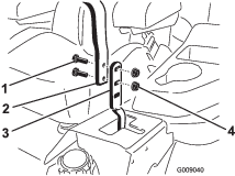

-
If the ends of the levers hit against each other, refer to Adjusting the Motion-Control Neutral-Lock Pivot.
-
Repeat to adjust the control levers.
Adjusting the Motion-Control Linkage
Located on either side of the machine, below the seat, are the pump-control linkages. Rotating the end nut with a 1/2-inch deep socket wrench allows fine tuning adjustments so that the machine does not move in neutral. Any adjustments should be made for neutral positioning only.
Warning
The engine must be running and the drive wheels turning so that you can perform the adjustments. Contact with moving parts or hot surfaces may cause personal injury.
Keep your fingers, hands, and clothing clear of rotating components and hot surfaces.
-
Disengage the blade-control switch (PTO), move the motion-control levers to the NEUTRAL-LOCK position, and engage the parking brake.
-
Shut off the engine, remove the key, and wait for all moving parts to stop before leaving the operating position.
-
Push the deck-lift pedal, and remove the height-of-cut pin.
-
Lower deck to the ground.
-
Raise the rear of machine up and support it with jack stands (or equivalent support).
Note: Raise the machine just high enough to allow the drive wheels to turn freely.
-
Remove the electrical connection from the seat safety switch, located under the bottom cushion of the seat.
Note: The switch is a part of the seat assembly.
-
Temporarily install a jumper wire across the terminals in the connector of the main wire harness.
-
Start the engine and run it at full throttle and disengage the brake.
Note: Before starting the engine, ensure that the parking brake is engaged and that the motion-control levers are out. You do not have to be in the seat.
-
Run the machine for at least 5 minutes with the drive levers at full forward speed to bring the hydraulic fluid up to the operating temperature.
Note: The motion-control levers must be in neutral while making any necessary adjustments.
-
Bring the motion-control levers into the NEUTRAL position.
-
Adjust the pump control rod lengths by rotating the double nuts on the rod in the appropriate direction until the wheels slightly creep in reverse (Figure 100).
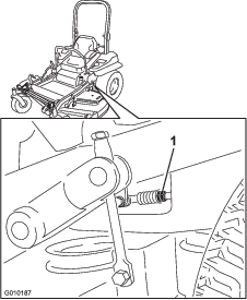
-
Move the motion-control levers to the REVERSE position and while applying slight pressure to the lever, allow the reverse-indicator springs to bring the levers back to neutral.
Note: The wheels must stop turning or slightly creep in reverse.
-
Shut off the machine.
-
Remove the jumper wire from the wire harness and plug the connector into the seat switch.
-
Remove the jack stands.
-
Raise the deck and install the height-of-cut pin.
-
Check that the machine does not creep in neutral with the park brakes disengaged.
Adjusting the Motion-Control Damper
You can adjust the top damper-mounting bolt to obtain the desired motion-control lever resistance. Refer to Figure 101 for mounting options.
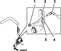
Adjusting the Motion-Control Neutral-Lock Pivot
You can adjust the flanged nut to obtain the desired motion-control lever resistance when moving it to the NEUTRAL-LOCK position. See Figure 102 for adjustment options.
-
Loosen the jam nut.
-
Tighten or loosen the flanged nut to the desired feel.
-
For more resistance, tighten the flanged nut.
-
For less resistance, loosen the flanged nut
-
-
Tighten the jam nut.
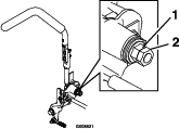
Hydraulic System Maintenance
Hydraulic System Safety
-
Seek immediate medical attention if fluid is injected into skin. Injected fluid must be surgically removed within a few hours by a doctor.
-
Ensure that all hydraulic-fluid hoses and lines are in good condition and all hydraulic connections and fittings are tight before applying pressure to the hydraulic system.
-
Keep your body and hands away from pinhole leaks or nozzles that eject high-pressure hydraulic fluid.
-
Use cardboard or paper to find hydraulic leaks.
-
Safely relieve all pressure in the hydraulic system before performing any work on the hydraulic system.
Servicing the Hydraulic System
Hydraulic-Fluid Specifications
Hydraulic-Fluid Type: Toro® HYPR-OIL™ 500 hydraulic fluid or Mobil® 1 15W-50.
Important: Use the specified fluid. Other fluids could damage the hydraulic system.
Each Hydraulic-System Fluid Capacity: 1.5 L (52 oz) per side with filter change
Checking the Hydraulic Fluid
| Maintenance Service Interval | Maintenance Procedure |
|---|---|
| Every 50 hours |
|
-
Park the machine on a level surface, disengage the blade-control switch (PTO), and engage the parking brake.
-
Shut off the engine, remove the key, and wait for all moving parts to stop before leaving the operating position.
-
Allow the engine and the hydraulic system to cool for 10 minutes.
Note: The oil level on the dipstick is incorrect when the oil is checked and the machine is hot.
-
Move the seat forward.
-
Clean the area around the dipsticks of hydraulic-system reservoirs (Figure 103).
-
Remove 1 dipstick from the hydraulic reservoir (Figure 103).
-
Wipe the dipstick off and thread the dipstick into the reservoir.
-
Remove the dipstick and look at the end (Figure 103).
Important: Do not overfill the hydraulic units with fluid, as damage may occur. Do not run the machine with fluid below the add mark.
-
If the fluid level is at the add mark, slowly pour only enough fluid into the hydraulic reservoir to raise the level to the full or H line.
-
Install the dipstick.
-
Repeat the procedure for the opposite dipstick.
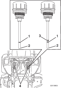
Replacing the Hydraulic Fluid and Filters
| Maintenance Service Interval | Maintenance Procedure |
|---|---|
| After the first 250 hours |
|
| Every 250 hours |
|
| Every 500 hours |
|
To replace the hydraulic fluid, the filters need to be removed. Replace both at the same time; refer to Hydraulic-Fluid Specifications for the oil specifications.
-
Park the machine on a level surface, disengage the blade-control switch, and engage the parking brake.
-
Shut off the engine, remove the key, and wait for all moving parts to stop before leaving the operating position.
-
Raise the machine and support it with jack stands (Figure 104).
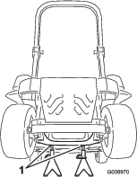
-
Remove both the mower belt and the pump-drive belt; refer to Replacing the Mower Belt for Side-Discharge Mower Decks or Replacing the Mower Belt for Rear-Discharge Mower Decks, and refer to Replacing the Hydraulic Pump-Drive Belt.
Note: This prevents oil from getting on the belts.
-
Place a drain pan under the filter, remove the old filter, and wipe the surface clean (Figure 105).
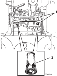
-
Apply a thin coat of hydraulic fluid to the rubber gasket on the replacement filter (Figure 105).
-
Install the replacement hydraulic filter.
-
Install the pump-drive belt and the mower belt.
-
Remove the jack stands and lower the machine (Figure 104).
-
Add fluid to the hydraulic reservoir and check for any leaks.
-
Clean up any spilled fluid.
-
Start the engine and let it run for about 2 minutes to purge air from the system.
-
Shut off the engine and check for leaks.
-
Check the fluid level while the fluid is cold.
-
If required, add fluid to the hydraulic reservoir.
Note: Do not overfill.
Mower Deck Maintenance
Leveling the Mower Deck
Leveling the Deck
-
Park the machine on a level surface, disengage the blade-control switch (PTO), and engage the parking brake.
-
Shut off the engine, remove the key, and wait for all moving parts to stop before leaving the operating position.
-
Check the tire pressure in the drive tires; refer to Checking the Tire Pressure.
-
Position the transport lock in the latching position.
-
Push the deck-lift pedal all the way forward and the deck latches at the 14 cm (5-1/2 inches) transport position (Figure 106).
-
Insert the height-adjustment pin into the 7.6 cm (3 inches) cutting-height location.
-
Release the transport lock and allow the deck to lower to the cutting height.
-
Raise the discharge chute.
-
On both sides of the deck, measure from the level surface to the front tip of the blade (Postion A) as shown in Figure 107.
Note: The measurement should read 7.6 mm (3 inches)
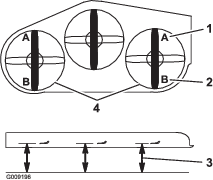
-
Fine-tune the adjustment nut on the front deck-lift assembly by turning it (Figure 108).
Note: To increase the height, turn the adjustment nut clockwise; to decrease the height, turn the nut counterclockwise.
Note: If the front deck links do not have enough adjustment to achieve accurate cut height, the single-point adjustment can be utilized to gain more adjustment.
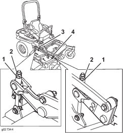
-
To adjust the single-point system, loosen the 2 bolts at the bottom of the height-of-cut plate (Figure 109).
Note: For rear-discharge machines, the mower deck is attached in the back holes at the factory. Refer to Figure 110. If needed, use the front holes for further adjustment when leveling the mower deck.
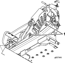
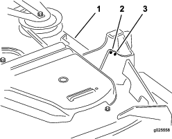
-
If the deck is too low, tighten the single-point-adjustment bolt by rotating it clockwise. If the deck is too high, loosen the single-point-adjustment bolt by rotating it counterclockwise (Figure 111).
Note: Loosen or tighten the single-point adjustment bolt enough to move the height-of-cut plate mounting bolts at least 1/3 the length of the available travel in their slots. This regains some up and down adjustment on each of the 4 deck links.
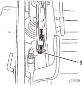
-
Tighten the 2 bolts at the bottom of the height-of-cut plate (Figure 109).
Note: In most conditions, the back blade tip should be adjusted 6.4 mm (1/4 inch) higher than the front.
-
Torque the 2 bolts to 37 to 45 N∙m (27 to 33 ft-lb).
-
On both sides of the deck, measure from the level surface to the back tip of the blade (postion B) as shown in Figure 107.
Note: The measurement should read 8.3 cm (3-1/4 inches)
-
Fine tune the screw adjuster by turning it to get 8.3 mm (3-1/4 inches) height (Figure 108).
To increase the height, turn the adjustment nut clockwise; to decrease, turn counterclockwise.
-
Measure until all 4 sides are the correct height.
-
Tighten all of the nuts on the deck-lift-arm assemblies.
-
Lower the discharge chute.
Servicing the Cutting Blades
To ensure a superior quality of cut, keep the blades sharp. For convenient sharpening and replacement, you may want to keep extra blades on hand.
Blade Safety
A worn or damaged blade can break, and a piece of the blade could be thrown toward you or bystanders, resulting in serious personal injury or death. Trying to repair a damaged blade may result in discontinued safety certification of the product.
-
Inspect the blades periodically for wear or damage.
-
Use care when checking the blades. Wrap the blades or wear gloves, and use caution when servicing the blades. Only replace or sharpen the blades; never straighten or weld them.
-
On multi-bladed machines, take care as rotating 1 blade can cause other blades to rotate.
Before Inspecting or Servicing the Blades
-
Park the machine on a level surface, disengage the blade-control switch (PTO), and engage the parking brake.
-
Shut off the engine, remove the key, and disconnect the spark-plug wires from the spark plugs.
Inspecting the Blades
| Maintenance Service Interval | Maintenance Procedure |
|---|---|
| Before each use or daily |
|
-
Inspect the cutting edges (Figure 112).
-
If the edges are not sharp or have nicks, remove and sharpen the blade; refer to Servicing the Cutting Blades.
-
Inspect the blades, especially in the curved area.
-
If you notice any cracks, wear, or a slot forming in this area, immediately install a new blade (Figure 112).
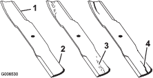
Checking for Bent Blades
-
Rotate the blades until the ends face forward and backward.
-
Measure from a level surface to the cutting edge, position A, of the blades (Figure 113).
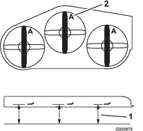
-
Rotate the opposite ends of the blades forward.
-
Measure from a level surface to the cutting edge of the blades at the same position as in step 2 above.
Note: The difference between the dimensions obtained in steps 2 and 4 must not exceed 3 mm (1/8 inch).
Note: If this dimension exceeds 3 mm (1/8 inch), the blade is bent and must be replaced.
Removing the Blades
Side-Discharge Machines
Replace the blades if they hit a solid object, or if the blade is out of balance or bent.
-
Hold the blade end using a rag or thickly padded glove.
-
Remove the blade bolt, curved washer, and blade from the spindle shaft (Figure 114).
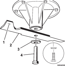
Rear-Discharge Machines
Important: The right blade on this mower deck is counter-rotating and uses a left-threaded blade bolt.
Replace a blade if it hits an object, if the blade is out of balance, or if the blade is bent. To ensure optimum performance and continued safety conformance of the machine, use genuine Toro replacement blades. Replacement blades made by other manufacturers may result in nonconformance with safety standards.
-
Hold the blade end using a rag or thickly-padded glove.
-
Remove the left and center blade bolt, curved washer, and blade from the spindle shaft (Figure 115).
-
Remove the right blade bolt (left threaded bolt), curved washer, and blade from the spindle shaft (Figure 115).
Note: Note the type of blade and where each blade is installed. See Figure 116 for the correct position.
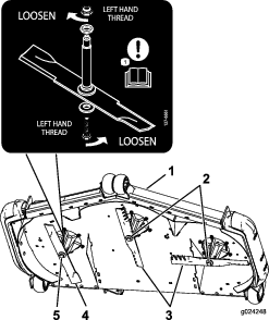
Sharpening the Blades
-
Use a file to sharpen the cutting edge at both ends of the blade (Figure 117).
Note: Maintain the original angle.
Note: The blade retains its balance if the same amount of material is removed from both cutting edges.

-
Check the balance of the blade by putting it on a blade balancer (Figure 118).
Note: If the blade stays in a horizontal position, the blade is balanced and can be used.
Note: If the blade is not balanced, file some metal off the end of the sail area only (Figure 117).
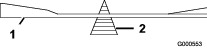
-
Repeat this procedure until the blade is balanced.
Installing the Blades
Side-Discharge Machines
-
Install the blade onto the spindle shaft (Figure 114).
Important: The curved part of the blade must point upward toward the inside of the mower to ensure proper cutting.
-
Install the curved washer and blade bolt (Figure 114).
Note: Install the curved-washer cone toward the bolt head.
-
Torque the blade bolt to 115 to 150 N∙m (85 to 110 ft-lb).
Rear-Discharge Machines
Important: The right blade on this mower deck is counter-rotating and uses a left-threaded blade bolt. Use Figure 116 for the correct placement of the mower blades.
-
Install the left and center blades, curved washers, and blade bolts to the spindle shafts (Figure 115 and Figure 116).
Important: The curved part of the blade must point upward toward the inside of the mower to ensure proper cutting.
Note: Install the curved-washer cone towards the bolt head (Figure 115).
-
Install the right blade, curved washer, and blade bolt (left-threaded bolt) to the spindle shaft (Figure 115 and Figure 116).
-
Torque the blade bolt to 115 to 150 N∙m (85 to 110 ft-lb).
Removing the Mower Deck
Lock out the spring-loaded deck arms before servicing or removing the mower deck.
Warning
Deck-lift arm assemblies have stored energy. Removing the deck with out releasing the stored energy can cause serious injury or death.
Do not attempt to disassemble the deck from the front frame without locking out the stored energy.
-
Park the machine on a level surface, disengage the blade-control switch (PTO), and engage the parking brake.
-
Shut off the engine, remove the key, and wait for all moving parts to stop before leaving the operating position.
-
Place the height adjustment pin in the 7.6 cm (3 inch) cutting-height location.
Note: This locks the deck-lift arms in the lowest position when the deck is removed and the stored energy in the deck spring is released.
-
Remove the belt covers.
-
Lift up the floor pan and insert a ratchet into the square hole in the deck idler (Figure 119 or Figure 120).
-
Rotate the deck idler clockwise, lift up on the belt-guide tab (rear-discharge machines only), and remove the mower belt (Figure 119 or Figure 120).
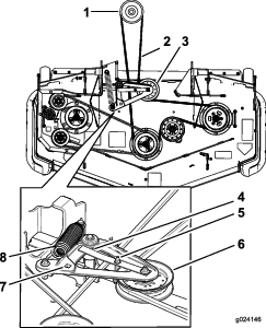
-
Remove and retain the hardware on both sides of the deck as shown in Figure 121.
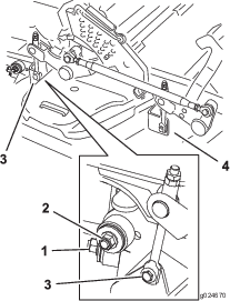
-
Raise the deck struts and secure them in the raised position.
-
Slide the deck out to the right side of the machine.
Replacing the Grass Deflector
Side-Discharge Machines Only
Warning
An uncovered discharge opening could allow the machine to throw objects toward you or bystanders, resulting in serious injury. Also, contact with the blade could occur.
Never operate the machine unless you install a mulch plate, discharge deflector, or grass collection system.
-
Remove the locknut, bolt, spring, and spacer holding the deflector to the pivot brackets (Figure 122).
-
Remove the damaged or worn grass deflector (Figure 122).
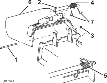
-
Place the spacer and the spring onto grass deflector.
-
Place 1 J-hook end of the spring behind the deck edge.
Note: Make sure that 1 J-hook end of the spring is installed behind the deck edge before installing the bolt as shown in Figure 122.
-
Install the bolt and the nut.
-
Place 1 J-hook end of the spring around the grass deflector (Figure 122).
Important: The grass deflector must be able to rotate. Lift the deflector up to the full open position and ensure that it rotates into the full down position.
Cleaning
Cleaning under the Mower Deck
| Maintenance Service Interval | Maintenance Procedure |
|---|---|
| Before each use or daily |
|
-
Park the machine on a level surface, disengage the blade-control switch (PTO), and engage the parking brake.
-
Shut off the engine, remove the key, and wait for all moving parts to stop before leaving the operating position.
-
Raise the mower deck to the TRANSPORT position.
Cleaning the Suspension System
Machines with MyRide™ Suspension System Only
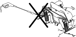
| Maintenance Service Interval | Maintenance Procedure |
|---|---|
| Before each use or daily |
|
Use compressed air to clean the suspension system.
Note: Do not clean the shock assemblies with pressurized water (Figure 123).
Disposing of Waste
Engine oil, batteries, hydraulic fluid, and engine coolant are pollutants to the environment. Dispose of these according to your state and local regulations.
Storage
Storage Safety
-
Shut off the engine, remove the key, wait for all moving parts to stop, and allow the machine to cool before storing it.
-
Do not store the machine or fuel near flames or drain the fuel indoors.
-
Remove the key and store it in a safe place out of the reach of children.
Cleaning and Storage
-
Disengage the blade-control switch (PTO), and engage the parking brake.
-
Shut off the engine, remove the key, and wait for all moving parts to stop before leaving the operating position.
-
Remove grass clippings, dirt, and grime from the external parts of the entire machine, especially the engine and hydraulic system. Clean dirt and chaff from the outside of the engine cylinder head fins and blower housing.
Important: You can wash the machine with mild detergent and water. Do not pressure wash the machine. Avoid excessive use of water, especially near the control panel, engine, hydraulic pumps, and motors.
-
Check the parking brake operation; refer to Operating the Parking Brake.
-
Service the air cleaner; refer to Servicing the Air Cleaner.
-
Grease the machine; refer to Lubrication.
-
Change the crankcase oil; refer to Changing the Engine Oil.
-
Check the tire pressure; refer to Checking the Tire Pressure.
-
Change the hydraulic filters; refer to Replacing the Hydraulic Fluid and Filters.
-
Charge the battery; refer to Charging the Battery.
-
Scrape any heavy buildup of grass and dirt from the underside of the mower, then wash the mower with a garden hose.
Note: Run the machine with the blade-control switch (PTO) engaged and the engine at high idle for 2 to 5 minutes after washing.
-
Check the condition of the blades; refer to Servicing the Cutting Blades.
-
Prepare the machine for storage when non-use occurs over 30 days. Prepare the machine for storage as follows:
-
Add a petroleum-based stabilizer/conditioner to fuel in the tank. Follow mixing instructions from the stabilizer manufacturer. Do not use an alcohol-based stabilizer (ethanol or methanol).
Note: A fuel stabilizer/conditioner is most effective when mixed with fresh fuel and used at all times.
-
Run the engine to distribute conditioned fuel through the fuel system for 5 minutes.
-
Shut off the engine, allow it to cool, and drain the fuel tank.
-
Start the engine and run it until it stops.
-
Dispose of fuel properly. Recycle the fuel according to local codes.
Important: Do not store fuel containing stabilizer/conditioner longer than the duration recommended by the fuel-stabilizer manufacturer.
-
-
Remove and check the condition of the spark plug(s); refer to Servicing the Spark Plug. With the spark plug(s) removed from the engine, pour 30 ml (2 tablespoons) of engine oil into the spark plug hole. Use the starter to crank the engine and distribute the oil inside the cylinder. Install the spark plug(s). Do not install the wire on the spark plug(s).
-
Check and tighten all bolts, nuts, and screws. Repair or replace any part that is damaged.
-
Paint all scratched or bare metal surfaces. Paint is available from your Authorized Service Dealer.
-
Store the machine in a clean, dry garage or storage area. Remove the key from the switch and keep it out of reach of children or other unauthorized users. Cover the machine to protect it and keep it clean.
Troubleshooting
| Problem | Possible Cause | Corrective Action |
|---|---|---|
| The starter does not crank. |
|
|
| The engine does not start, starts hard, or fails to keep running. |
|
|
| The engine loses power. |
|
|
| The engine overheats. |
|
|
| The machine pulls to the left or right (with levers fully forward) |
|
|
| The machine does not drive. |
|
|
| The machine vibrates abnormally. |
|
|
| The cutting height is uneven. |
|
|
| The blades do not rotate. |
|
|
| The clutch does not engage. |
|
|
Schematics
Wire Diagram