Setup
Preparing the Machine
Caution
If you leave the key in the ignition switch, someone could accidently start the engine and seriously injure you or bystanders.
Remove the key from the ignition switch before you do any maintenance.
-
Park the machine on a level surface.
-
Engage the parking brake.
-
Lower the cutting units.
-
Shut off the engine and remove the key.
Disconnecting the Battery
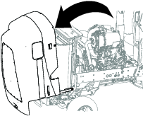
Accessing the Battery
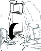
Release the latch and open the door to the battery compartment (Figure 1).
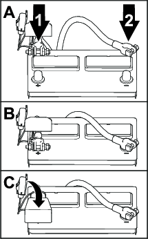
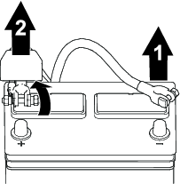
Removing the Battery Cables
Warning
Battery terminals or metal tools could short against metal components, causing sparks.
-
When removing or installing the battery, do not allow the battery terminals to touch any metal parts of the machine.
-
Do not allow metal tools to short between the battery terminals and metal parts of the machine.
-
Always keep the battery strap in place to protect and secure the battery.
Warning
Electrical sparks can cause the battery gasses to explode, resulting in personal injury.
Incorrect battery cable routing could damage the machine and cables, causing sparks.
-
Always disconnect the negative (black) battery cable before disconnecting the positive (red) cable.
-
Always connect the positive (red) battery cable before connecting the negative (black) cable.
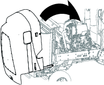
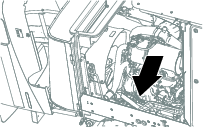
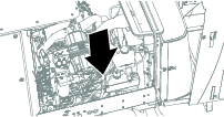
Opening the Hood
Unlatch and open the hood (Figure 3).
Routing and Connecting the Power Harness
Parts needed for this procedure:
| Power harness | 1 |
| Cable tie | 6 |
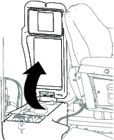
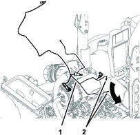
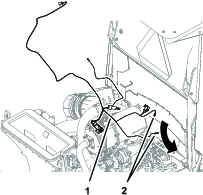
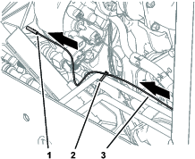
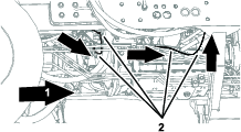
Routing the Ring Terminals to the Battery and Electrical Compartment
Important: Route the power harness away from exhaust components and moving parts.
-
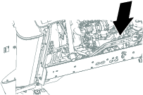
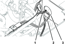
Route the 2 ring terminals of the power harness under the area where the battery compartment is located (Figure 4 or Figure 5).
-
Route the ring terminal of the power harness labeled B+ through the opening at the back, outboard corner battery compartment (Figure 6).
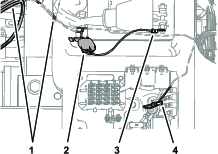
-
Route the ring terminal of the power harness labeled GROUND BLOCK under the battery compartment and through the opening near the forward inboard corner of the electrical compartment (Figure 6).
Assembling the Ring Terminals to the Battery Cable and Ground Block
-
Remove the battery-clamp nut from the battery clamp bolt of the positive battery cable (Figure 14).
-
Assemble the ring terminal labeled B+ onto the battery clamp bolt with the clamp nut, and tighten the nut by hand (Figure 7).
-
Remove the screw from the ground block (Figure 8).
-
Assemble the ring terminal labeled GROUND BLOCK to the ground block with the screw and tighten the it by hand (Figure 8).
Connecting the Power Harness to the Machine Harness
-
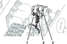
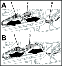
Remove the cap from the from the 2-pin connector of the machine wire harness labeled CAB HARNESS (Figure 9).
-
Plug the 2-pin connector of the machine wire harness into the 2-socket connector of the power harness labeled MAIN HARNESS (Figure 9).
-
Secure the power harness to the frame of the machine with a cable tie (Figure 10).
Connecting the Power Harness to the Optional Sunshade or 2-Post ROPS Extension Harnesses
Connect the 2-socket connector of the power harness labeled CAB HARNESS into the 2-pin connector of the sunshade wire harness (Figure 11).
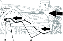
Bundling the Air Conditioner Wire and the Water Pump Wires
Routing the Air Conditioner Wire and the Water Pump Wires
-
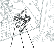
Route the wire and bullet terminal labeled A/C CLUTCH rearward along the right side of the engine (Figure 13).
-
Secure the wire to the tube with a cable tie (Figure 13).
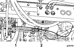
-
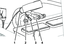
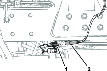
Route the wires with the 2-socket connector labeled WATER PUMP across the front of the engine and rearward (Figure 14).
-
Route the wires with the 2-socket connector to the washer-fluid tank (Figure 15).
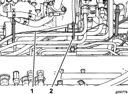
-
Secure the water pump wires of the power harness to the hydraulic hoses and tubes at the locations shown in Figure 16 and Figure 17.
-
Refer to the cab kit Installation Instructions for the connecting the air conditioner connector and water pump connector.
Connecting the Battery
Warning
Electrical sparks can cause the battery gasses to explode, resulting in personal injury.
Incorrect battery cable routing could damage the machine and cables, causing sparks.
-
Always disconnect the negative (black) battery cable before disconnecting the positive (red) cable.
-
Always connect the positive (red) battery cable before connecting the negative (black) cable.