


Maintenance
Recommended Maintenance Schedule(s)
| Maintenance Service Interval | Maintenance Procedure |
|---|---|
| After the first 100 operating hours |
|
| After the first 250 operating hours |
|
| Before each use or daily |
|
| Every 50 hours |
|
| Every 100 hours |
|
| Every 150 hours |
|
| Every 200 hours |
|
| Every 250 hours |
|
| Every 300 hours |
|
| Every 500 hours |
|
| Every 600 hours |
|
| Monthly |
|
| Yearly |
|
| Yearly or before storage |
|
Important: Refer to your engine operator's manual for additional maintenance procedures.
Caution
If you leave the key in the ignition switch, someone could accidently start the engine and seriously injure you or other bystanders.
Remove the key from the ignition before you do any maintenance.
Lubrication
Grease more frequently when operating conditions are extremely dusty or sandy.
Grease Type: No. 2 lithium or molybdenum-base grease
-
Disengage the blade-control switch (PTO), move the motion-control levers to the NEUTRAL-LOCK position, and set the parking brake.
-
Shut off the engine, remove the key, and wait for all moving parts to stop before leaving the operating position.
-
Clean the grease fittings with a rag.
Note: Make sure to scrape any paint off the front of the fitting(s).
-
Connect a grease gun to the fitting and pump grease into the fittings until grease begins to ooze out of the bearings.
-
Wipe up any excess grease.
Adding Light Oil or Spray Lubrication
Lubricate the deck lift pivots.
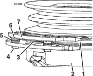
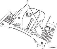
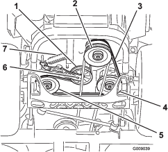
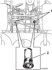
Greasing the Mower
-
Disengage the blade-control switch (PTO), move the motion-control levers to the NEUTRAL-LOCK position, and set the parking brake.
-
Shut off the engine, remove the key, and wait for all moving parts to stop before leaving the operating position.
-
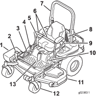
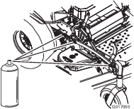
Grease the mower-deck idler-pulley pivot until grease come out the bottom (Figure 45).
-
Grease the 3 spindle bearings until grease comes out the lower seals (Figure 45).
-
Grease the drive-belt idler arm (Figure 45).
-
Remove the dust cap and adjust the caster pivots.
Note: Keep the dust cap off until greasing is complete. Refer to Adjusting the Caster-Pivot Bearing.
-
Remove the hex plug and thread a grease fitting into the hole.
-
Pump grease into the fitting until it oozes out around the top bearing.
-
Remove the grease fitting from the hole.
-
Install the hex plug and dust cap (Figure 47).
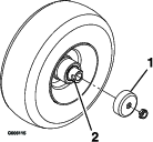
Lubricating the Caster-Wheel Hubs
-
Shut off the engine, wait for all moving parts to stop, remove the key, and engage the parking brake.
-
Remove the caster wheel from the caster forks.
-
Remove the seal guards from the wheel hub.
-
Remove a spacer nut from the axle assembly in the caster wheel.
Note: Thread-locking compound has been applied to lock the spacer nuts to the axle.
-
Remove the axle (with the other spacer nut still assembled to it) from the wheel assembly.
-
Pry out seals and inspect bearings for wear or damage and replace if necessary.
-
Pack the bearings with a general-purpose grease.
-
Insert 1 bearing and 1 new seal into the wheel.
Note: Replace the seals.
-
If both spacer nuts have been removed (or broken loose) from the axle assembly, apply a thread-locking compound to 1 spacer nut and thread it onto the axle with the wrench flats facing outward.
Note: Do not thread the spacer nut all of the way onto the end of the axle. Leave approximately 3 mm (1/8 inch) from the outer surface of the spacer nut to the end of the axle inside the nut.
-
Insert the assembled nut and axle into the wheel on the side with the new seal and bearing.
-
With the open end of the wheel facing up, fill the area inside the wheel around the axle full of general-purpose grease.
-
Insert the second bearing and new seal into the wheel.
-
Apply a thread-locking compound to the second spacer nut and thread it onto the axle with the wrench flats facing outward.
-
Torque the nut to 8 to 9 N∙m (75 to 80 in-lb), loosen the nut, then torque it to 2 to 3 N∙m (20 to 25 in-lb).
Note: Make sure that the axle does not extend beyond either nut.
-
Install the seal guards over the wheel hub and insert wheel into the caster fork.
-
Install the caster bolt and tighten the nut fully.
Important: To prevent seal and bearing damage, check the bearing adjustment often. Spin the caster tire. The tire should not spin freely (more than 1 or 2 revolutions) or have any side play. If the wheel spins freely, adjust the torque on the spacer nut until there is a slight amount of drag. Apply another layer of thread-locking compound.
Engine Maintenance
Warning
Contact with hot surfaces may cause personal injury.
Keep hands, feet, face, clothing, and other body parts away the muffler and other hot surfaces.
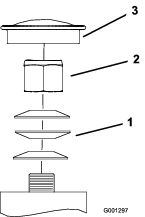
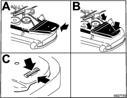
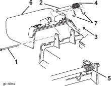
Servicing the Air Cleaner
Note: Check the filters more frequently if the operating conditions are extremely dusty or sandy.
Removing the Filters
-
Disengage the blade-control switch (PTO), move the motion-control levers to the NEUTRAL-LOCK position, and set the parking brake.
-
Shut off the engine, remove the key, and wait for all moving parts to stop before leaving the operating position.
-
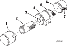
Release the latches on the air cleaner and pull the air-inlet cover off the air-cleaner body (Figure 49).
-
Clean the air-inlet screen and cover.
-
Install the air-inlet cover and secure it with the latches (Figure 49).
-
Release the latches on the air cleaner and pull the air-cleaner cover off the air-cleaner body (Figure 49).
-
Clean the inside of the air-cleaner cover with compressed air.
-
Gently slide the primary filter out of the air-cleaner body (Figure 49).
Note: Avoid knocking the filter into the side of the body.
-
Remove the inner filter only if you intend to replace it.
Important: Never attempt to clean the inner filter. If the safety filter is dirty, then the primary filter is damaged; replace both filters.
-
Inspect the primary filter for damage by looking into the filter while shining a bright light on the outside of the filter.
Note: Any holes in the filter appear as bright spots. If the filter is damaged, discard it.
Servicing the Primary Filter
-
If the primary filter is dirty, bent, or damaged, replace it.
-
Do not clean the primary filter.
Servicing the Safety Filter
Replace the safety filter, never clean it.
Important: Never attempt to clean the safety filter. If the safety filter is dirty, then the primary filter is damaged. Replace both filters.
Installing the Filters
Important: To prevent engine damage, always operate the engine with both air filters and the cover installed.
-
If you are installing new filters, check each filter for shipping damage.
Note: Do not use a damaged filter.
-
If you are replacing the inner filter, carefully slide it into the filter body (Figure 49).
-
Carefully slide the primary filter over the inner filter (Figure 49).
Note: Ensure that the primary filter is fully seated by pushing on its outer rim while installing it.
Important: Do not press on the soft inside area of the filter.
-
Install the air-cleaner cover and secure the latches (Figure 49).
Servicing the Engine Oil
Oil Type: Detergent oil (API service class SL, SM, SN, or higher)
Oil Capacity: with a filter change, 1.9 L (2.0 US qt); with no filter change, 1.6 L (1.7 US qt)
Viscosity: See the table below.
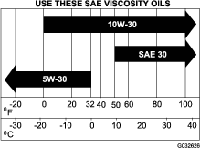
Note: Use of synthetic oil having 5W-20 or 5W-30 rating is acceptable, up to 4 degrees C (40 degrees F).
Note: Synthetic oils will provide better starting in extreme cold below -23 degrees C (-10 degrees F).
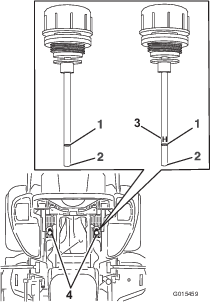
Checking the Engine-Oil Level
Note: Check the oil when the engine is cold.
Warning
Contact with hot surfaces may cause personal injury.
Keep hands, feet, face, clothing and other body parts away from the muffler and other hot surfaces.
Important: Do not overfill the crankcase with oil because damage to the engine may result. Do not run engine with oil below the low mark because the engine may be damaged.
-
Disengage the blade-control switch (PTO), move the motion-control levers to the NEUTRAL-LOCK position, and set the parking brake.
-
Shut off the engine, remove the key, and wait for all moving parts to stop before leaving the operating position (Figure 51).
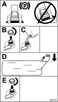
Changing the Engine Oil
Note: Dispose of the used oil at a recycling center.
-
Start the engine and let it run for 5 minutes.
Note: This warms the oil so that it drains better.
-
Park the machine so that the rear is slightly lower than the front to ensure that the oil drains completely.
-
Disengage the blade-control switch (PTO), move the motion-control levers to the NEUTRAL-LOCK position, and set the parking brake.
-
Shut off the engine, remove the key, and wait for all moving parts to stop before leaving the operating position (Figure 52).
-
Slowly pour approximately 80% of the specified oil into the filler tube and slowly add the additional oil to bring it to the Full mark (Figure 53).
-
Start the engine and drive to a flat area. Check the oil level again.
Changing the Engine-Oil Filter
Note: Change the engine oil filter more frequently when operating conditions are extremely dusty or sandy.
-
Drain the oil from the engine; refer to Changing the Engine Oil.
-
Change the engine oil filter (Figure 54).
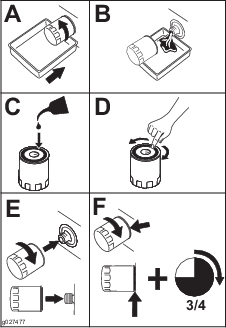
Note: Ensure the oil filter gasket touches the engine and then an extra 3/4 turn is completed.
-
Fill the crankcase with the proper type of new oil; refer to Changing the Engine Oil.
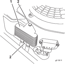
Servicing the Engine-Oil Cooler
-
Keep the oil cooler free of debris by cleaning the fins with a brush.
-
Remove the bolts holding the oil cooler to the engine housing.
-
Clean the inside of the oil cooler with a brush.
-
Install the oil cooler to the engine housing.
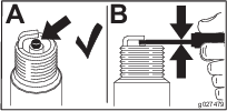
Servicing the Spark Plug
Make sure that the air gap between the center and side electrodes is correct before installing the spark plug. Use a spark plug wrench to remove and install the spark plug(s) and use a gapping tool/feeler gauge to check and adjust the air gap. Install a new spark plug(s) if necessary.
Type : Champion® XC12YC, or equivalent
Air Gap: 0.76 mm (0.030 inch)
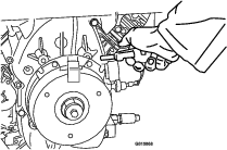
Removing the Spark Plug
-
Shut off the engine, remove the key, and wait for all moving parts to stop before leaving the operating position.
-
Disengage the blade-control switch (PTO), move the motion-control levers to the NEUTRAL-LOCK position, and set the parking brake.
-
Remove the left hydraulic unit shroud in the order listed with Figure 56.
Note: This gives you access to the front spark plug.

-
Remove the spark plug (Figure 57).
-
Install the left hydraulic unit shroud (Figure 56).
Checking the Spark Plug
Important: Replace the spark plug(s) when it has: a black coating, worn electrodes, an oily film, cracks or reuse is questionable.
If you see light brown or gray on the insulator, the engine is operating properly. A black coating on the insulator usually means the air cleaner is dirty.
Set the gap to 0.76 mm (0.030 inches).
Installing the Spark Plug
Tighten the spark plug(s) to 24.4 to 29.8 N∙m (18 to 22 ft-lb).
Checking the Spark Arrester (if Equipped)
Warning
Hot exhaust system components may ignite gasoline vapors even after you shut off the engine. Hot particles exhausted during engine operation may ignite flammable materials. Fire may result in personal injury or property damage.
Do not refuel or run the engine unless a spark arrester is installed.
-
Shut off the engine, wait for all moving parts to stop, and remove key. Engage parking brake.
-
Wait for the muffler to cool.
-
If there are any breaks in the screen or welds, replace the arrester.
-
If the screen is plugged, remove the arrester and shake the loose particles out of the arrester and clean the screen with a wire brush (soak it in solvent if necessary). Install the arrester on the exhaust outlet.
Fuel System Maintenance
Warning
Fuel-system components are under high pressure. The use of improper components can result in system failure, gasoline leakage, and possible explosion.
Use only approved fuel lines and fuel filters.
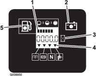
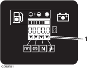
Servicing the Electronic Fuel-Injection System
This machine contains an electronic fuel-injection system. It controls the fuel flow under different operating conditions.
The electronic control unit (ECU) continuously monitors the operation of the EFI system.
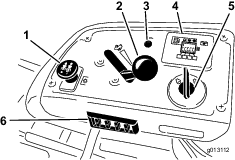
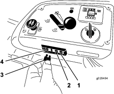
If a problem or fault within the system is detected, the malfunction indicator light (MIL) illuminates. The MIL is the red light located in the right console panel.
Once the MIL illuminates, make initial troubleshooting checks. Refer to the MIL section under .
If these checks do not correct the problem, further diagnosis and servicing by an Authorized Service Dealer is necessary.
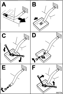
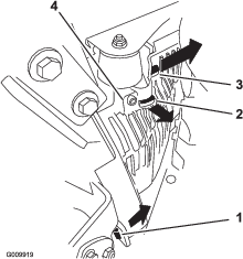
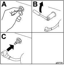
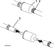
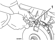
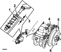
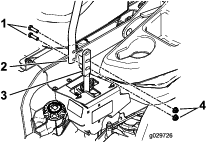
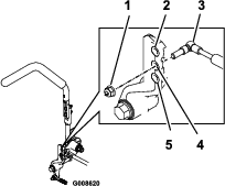
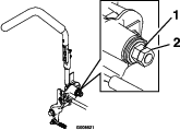
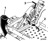
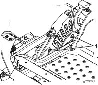
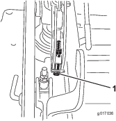
Replacing the Low-Pressure Fuel Filter
The fuel filter is located near the engine on the front or rear side of the engine.
-
Disengage the blade-control switch (PTO), move the motion-control levers to the NEUTRAL-LOCK position, and set the parking brake.
-
Shut off the engine, remove the key, and wait for all moving parts to stop before leaving the operating position.
-
Wait for the machine to cool down.
-
Close the fuel-shutoff valve under the seat (Figure 60).
-
Squeeze the ends of the hose clamps together and slide them away from the filter (Figure 60).
-
Remove the filter from the fuel lines.
-
Install a new filter and move the hose clamps close to the filter (Figure 60).
-
Open the fuel-shutoff valve.
Important: Install the fuel line hoses and secure with plastic ties the same as they were originally installed at the factory to keep the fuel line away from components that can cause fuel line damage.
Servicing the High-Pressure Fuel Filter
Do not attempt to service the high-pressure fuel filter. The high-pressure filter is integrated within the fuel-pump module. The fuel filter and other components inside the fuel-pump module are not serviceable.
Important: Do not attempt to open the fuel-pump module.
Ensure that an Authorized Service Dealer replaces the fuel-pump module with the high-pressure fuel filter.
Servicing the Fuel Tank
Do not attempt to drain the fuel tank. Ensure that an Authorized Service Dealer drains the fuel tank.
Electrical System Maintenance
Servicing the Battery
Danger
Battery electrolyte contains sulfuric acid, which is a deadly poison and causes severe burns.
Do not drink electrolyte and avoid contact with skin, eyes, or clothing. Wear safety glasses to shield your eyes and wear rubber gloves to protect your hands.
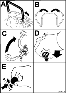
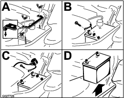
Removing the Battery
Warning
Battery terminals or metal tools could short against metal machine components, causing sparks. Sparks can cause the battery gasses to explode, resulting in personal injury.
-
When removing or installing the battery, do not allow the battery terminals to touch any metal parts of the machine.
-
Do not allow metal tools to short between the battery terminals and metal parts of the machine.
Warning
Incorrect battery cable routing could damage the machine and cables, causing sparks. Sparks can cause the battery gasses to explode, resulting in personal injury.
-
Always disconnect the negative (black) battery cable before disconnecting the positive (red) cable.
-
Always connect the positive (red) battery cable before connecting the negative (black) cable.
-
Disengage the blade-control switch (PTO), move the motion-control levers to the NEUTRAL-LOCK position, and set the parking brake.
-
Shut off the engine, remove the key, and wait for all moving parts to stop before leaving the operating position.
-
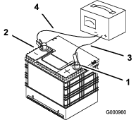
Disconnect the negative battery cable (black) from the negative (-) battery terminal (Figure 61).
-
Slide the red terminal boot off the positive (+) battery terminal and remove the positive (red) battery cable (Figure 61).
-
Remove the wing nut securing the battery clamp (Figure 61).
-
Remove the clamp (Figure 61).
-
Remove the battery (Figure 61).

Installing the Battery
-
Position battery in the tray with the terminal posts opposite from the hydraulic tank (Figure 61).
-
Install the positive (red) battery cable to the positive (+) battery terminal.
-
Install the negative (black) battery cable and ground wire to the negative (-) battery terminal.
-
Secure the cables with 2bolts, 2washers, and 2locknuts (Figure 61).
-
Slide the red terminal boot onto the positive (+) battery terminal.
-
Install the clamp and secure it with the wing nut (Figure 61).
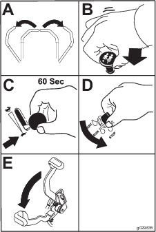
Charging the Battery
Warning
Charging the battery produces gasses that can explode.
Never smoke near the battery and keep sparks and flames away from battery.
Important: Always keep the battery fully charged (1.265specific gravity). This is especially important to prevent battery damage when the temperature is below 0°C (32°F).
-
Charge battery for 10 to 15minutes at 25 to 30 A or for 30 minutes at 10A.
-
When the battery is fully charged, unplug the charger from the electrical outlet, then disconnect the charger leads from the battery posts (Figure 62).
-
Install the battery in the machine and connect the battery cables; refer to Installing the Battery.
Note: Do not run the machine with the battery disconnected; otherwise, electrical damage may occur.
Servicing the Fuses
The electrical system is protected by fuses. It requires no maintenance, however, if a fuse blows check the component and circuit for a malfunction or short.
Jump-Starting the Machine
-
Check and clean corrosion from the battery terminals before jump-starting. Ensure that the connections are tight.
Caution
Corrosion or loose connections can cause unwanted electrical voltage spikes at any time during the jump-starting procedure.
Do not attempt to jump-start the machine with loose or corroded battery terminals, or damage to the engine or EFI may occur.
Danger
Jump-starting a weak battery that is cracked, frozen, or has a low electrolyte level or an open/shorted battery cell can cause an explosion, resulting in serious personal injury.
Do not jump-start a weak battery if these conditions exist.
-
Make sure that the booster battery is a good and fully charged lead-acid battery at 12.6 V or greater.
Note: Use properly sized jumper cables with short lengths to reduce voltage drop between systems. Make sure that the cables are color coded or labeled for the correct polarity.
Caution
Connecting the jumper cables incorrectly (wrong polarity) can immediately damage the EFI system.
Be certain of battery terminal polarity and jumper cable polarity when connecting the batteries.
Warning
Batteries contain acid and produce explosive gases.
-
Shield the eyes and face from the batteries at all times.
-
Do not lean over the batteries.
Note: Be sure that the vent caps are tight and level. Place a damp cloth, if available, over any vent caps on both batteries. Be sure that the vehicles do not touch and that both electrical systems are off and at the same rated system voltage. These instructions are for negative ground systems only.
-
-
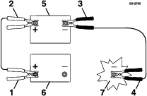
Connect the positive (+) cable to the positive (+) terminal of the discharged battery that is wired to the starter or solenoid as shown in Figure 64.
-
Connect the other end of the positive cable to the positive terminal of the booster battery.
-
Connect the black negative (–) cable to the other terminal (negative) of the booster battery.
-
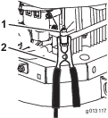
Make the final connection on the engine block of the stalled vehicle (not to the negative battery post) away from the battery and stand back (Figure 65).
-
Start the vehicle and remove the cables in the reverse order of connection..
Note: Disconnect the engine block (black) first.
Drive System Maintenance
Checking the Seat Belt
Inspect the seat belt for wear, cuts, and proper operation of the retractor and buckle. Replace the seat belt if it is damaged.
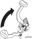
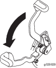
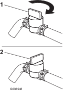
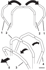
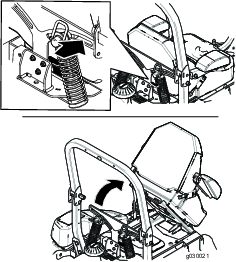
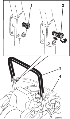
Checking the Rollover-Protection-System (ROPS) Knobs
Warning
To avoid injury or death from rollover: keep the roll bar in the fully raised locked position and use the seat belt.
Ensure that the seat is secured to the machine.
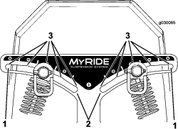
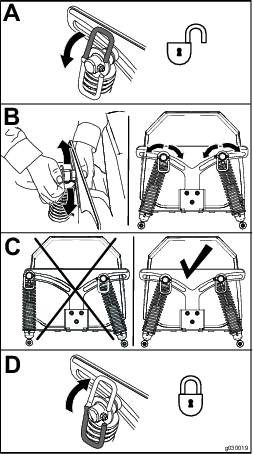
Check that both the mounting hardware and the knobs are in good working condition. Make sure that the knobs are fully engaged with the ROPS in the raised position. The upper hoop of the roll bar may need to be pushed forward or pulled rearward to fully engage both knobs (Figure 66).
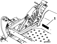
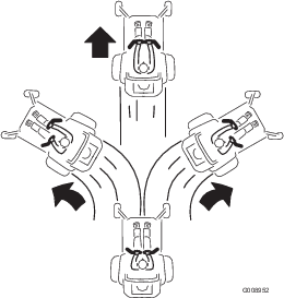
Adjusting the Tracking
-
Disengage the blade-control switch (PTO).
-
Drive to an open, flat area and move the motion-control levers to the NEUTRAL-LOCK position.
-
Move the throttle midway between the FAST and SLOW positions.
-
Move both motion-control levers forward until they both hit the stops in the T-slot.
-
Check which way the machine tracks.
-
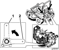
If the machine tracks to the right, loosen the bolts and adjust the left stop plate rearward on the left T-slot until the machine tracks straight (Figure 67).
-
If the machine tracks to the left, loosen the bolts and adjust the right stop plate rearward on the right T-slot until the machine tracks straight (Figure 67).
-
Tighten the stop plate (Figure 67).
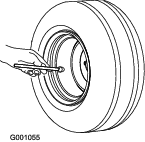
Checking the Tire Pressure
Maintain the air pressure in the rear tires at 90 kPa (13 psi). Uneven tire pressure can cause uneven cut. Check the tires when they are cold, to get the most accurate pressure reading.
Note: The front tires are semi-pneumatic tires and do not require air-pressure maintenance.
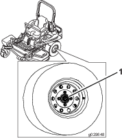
Checking the Wheel Lug Nuts
Check and torque the wheel lug nuts to 122 to 129 N∙m (90 to 95 ft-lb).
Checking the Wheel Hub Slotted Nut
Check and ensure that the torque of the slotted nut is 286 to 352 N∙m (211 to 260 ft-lb).
Note: Do not use anti-seize compound on the wheel hub.
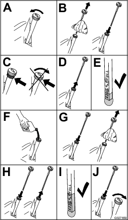
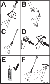
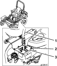
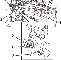
Adjusting the Caster-Pivot Bearing
-
Disengage the blade-control switch (PTO), move the motion-control levers to the NEUTRAL-LOCK position, and set the parking brake.
-
Shut off the engine, remove the key, and wait for all moving parts to stop before leaving the operating position.
-
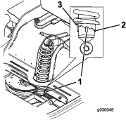
Remove the dust cap from caster and tighten the locknut (Figure 70).
-
Tighten the locknut until the spring washers are flat, and then back off a 1/4turn to properly set the preload on the bearings (Figure 70).
Important: Make sure that the spring washers are installed correctly as shown in Figure 70.
-
Install the dust cap (Figure 70).
Using the Clutch Shim
Some later model year units have been built with clutches that contain a brake shim. When the clutch brake has worn to the point where the clutch no longer engages consistently, you can remove the shim to extend the clutch life.
Removing the Clutch Shim
-
Shut off the engine, wait for all moving parts to stop, and remove the key.
-
Engage the parking brake and wait for machine to cool completely.
-
Using an air compressor, blow out any debris under the brake pole and around the brake spacers.
-
Check the condition of the wire-harness leads, connectors, and terminals. Clean or repair them as necessary.
-
Verify that 12 V is present at the clutch connector when the you engage the blade-control switch (PTO).
-
Measure the gap between the rotor and armature. If the gap is greater than 1 mm (0.04 inch), proceed with the following steps:
-
Loosen both brake mounting bolts 1/2 to 1 full turn as shown in Figure 73.
Note: Do not remove the brake pole from the field shell/armature. The brake pole has worn to match the armature and needs to continue to match after you remove the shim to ensure the proper brake torque.
-
Using needle-nose pliers, or by hand, remove the shim.
Note: Do not discard the shim until you confirm that the clutch functions properly.
-
Using a pneumatic line, blow out any debris under the brake pole and around the brake spacers.
-
Torque each bolt (M6 x 1) to 12.3 to 13.7 N∙m (9.5 to 10.5 ft-lb).
-
Using a 0.010 inch thick-feeler gauge, verify that a gap is present between the rotor and armature face on both sides of the brake pole as shown in Figure 75 and Figure 76.
Note: Due to the way the rotor and armature faces wear (peaks and valleys), it is sometimes difficult to measure the true gap.
-
If the gap is less than 0.010 inch, then install the shim and refer to .
-
If the gap is sufficient, proceed to the safety check in step 8.
-
-
Perform the following safety check:
-
Sit on the seat and start the engine.
-
Make sure that the blades do not engage when the blade-control switch (PTO) is in the OFF position and the clutch is disengaged.
Note: If the clutch does not disengage, install the shim, and refer to .
-
Engage and disengage the blade-control switch (PTO) 10 consecutive times to ensure that the clutch is functioning properly.
Note: If the clutch does not engage properly, refer to .
-
-
Cooling System Maintenance
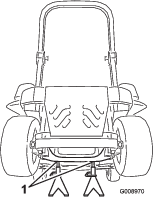
Cleaning the Engine Screen and Engine-Oil Cooler
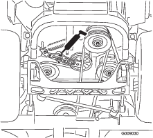
Remove any buildup of grass, dirt, or other debris from the oil cooler (Figure 77). This helps ensure adequate cooling, correct engine speed, and reduces the possibility of overheating and mechanical damage to the engine.

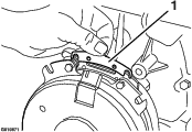
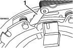
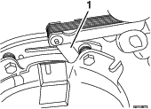
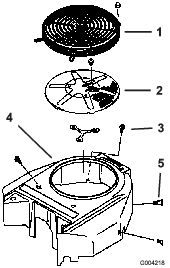
Cleaning the Engine Cooling Fins and Shrouds
-
Disengage the blade-control switch (PTO) and set the parking brake.
-
Shut off the engine, remove the key, and wait for all moving parts to stop before leaving the operating position.
-
Remove the air intake screen, recoil starter, and fan housing (Figure 78).
-
Clean the debris and grass from the engine parts.
-
Install the air-intake screen, recoil starter, and fan housing (Figure 78).
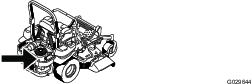
Cleaning the Hydraulic Units
-
Disengage the blade-control switch (PTO) and set the parking brake.
-
Shut off the engine, remove the key, and wait for all moving parts to stop before leaving the operating position.
-
Move the seat forward.
-
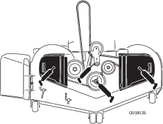
Clean the debris and grass from the hydraulic units (Figure 79).
-
Position the seat.
Brake Maintenance
Adjusting the Parking Brake
-
Drive the machine onto a level surface.
-
Disengage the blade-control switch (PTO), move the motion-control levers to the NEUTRAL-LOCK position, and engage the parking brake.
-
Shut off the engine, wait for all moving parts to stop, and remove the key.
-
Raise the back of the machine and support the machine with jack stands.
Danger
Mechanical or hydraulic jacks may fail to support machine and cause a serious injury.
-
Use a jack stand when supporting the machine.
-
Do not use hydraulic jacks.
-
-
Remove the rear tires from the machine.
-
Remove any debris from the brake area.
-
Rotate the drive-wheel release handle to the released position. Refer to Using the Drive-Wheel Release Valves.
-
Check if there is a visible gap between the L-bracket and the linkage stop (Figure 80).
-
Disengage the parking brake.
-
Turn the wheel hub by hand in both directions relative to the caliper.
Note: The wheel hub should move freely between the caliper.
-
If a gap is needed or the wheel hub does not move freely:
-
Disengage the parking brake.
-
Disconnect and fine-tune the rear linkage assembly:
-
Shorten the link to create a gap.
-
Lengthen the link to allow wheel hub movement.
-
-
Connect the rear-linkage assembly.
-
-
Engage the parking brake and check the gap.
-
Repeat steps 9 through 13 until you achieve a visible gap and the wheel hub rotates freely.
-
Repeat this procedure for the brake on the opposite side.
-
Rotate the drive-wheel release handle to the operating position; refer toUsing the Drive-Wheel Release Valves.
-
Install the rear tires and torque the lug nuts; refer to Checking the Wheel Lug Nuts.
-
Remove the jack stands.
Belt Maintenance
Inspecting the Belts
Replace the belt if it is worn. The signs of a worn belt include squealing while the belt is rotating; the blades slipping while cutting grass; and frayed edges, burn marks, and cracks on the belt.
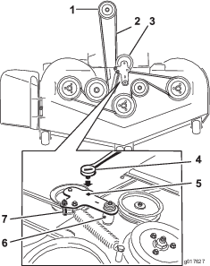
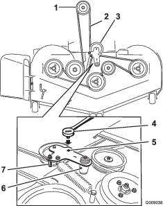
Replacing the Mower Belt
-
Disengage the blade-control switch (PTO), move the motion-control levers to the NEUTRAL-LOCK position, and set the parking brake.
-
Shut off the engine, remove the key, and wait for all moving parts to stop before leaving the operating position.
-
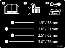
Lower the mower to the 76 mm (3 inch) height-of-cut.
-
Remove the belt covers (Figure 81).
-
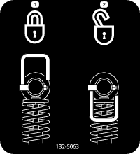
Use a ratchet in the square hole in the idler arm to remove tension on the idler spring (Figure 82).
-
Remove the belt from the mower-deck pulleys.
-
Remove the belt guide on the spring-loaded idler arm (Figure 82).
-
Remove the existing belt.
-
Install the new belt around the mower pulleys and the clutch pulley under the engine (Figure 82).
-
Install the belt guide on the idler arm (Figure 82).
-
Using the ratchet in the square hole, install the idler spring (Figure 82).
Note: Make sure to seat the spring ends in the anchor grooves.
-
Install the belt covers (Figure 83).
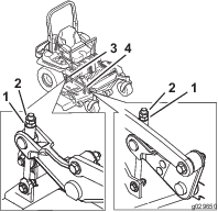
Replacing the Hydraulic-Pump Drive Belt
-
Disengage the blade-control switch (PTO) and set the parking brake.
-
Shut off the engine, remove the key, and wait for all moving parts to stop before leaving the operating position.
-
Remove mower belt; refer to Replacing the Mower Belt.
-
Raise the machine and support it with jack stands (Figure 84).
-
Use a ratchet in the square hole in the idler arm to remove the idler spring (Figure 84).
-
Unhook the idler spring from the frame (Figure 84).
-
Remove the belt from the hydraulic-unit-drive pulleys and the engine pulley.
-
Install the new belt around engine pulley and the 2 drive pulleys.
-
Using a ratchet in the square hole in the idler arm, install the idler spring to the frame (Figure 84).
-
Install the mower belt; refer to Replacing the Mower Belt.
Controls System Maintenance
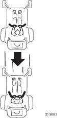
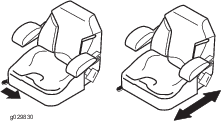
Adjusting the Control-Handle Position
There are 2 height positions for the control levers—high and low. Remove the bolts to adjust the height.
-
Disengage the blade-control switch (PTO), move the motion-control levers to the NEUTRAL-LOCK position, and set the parking brake.
-
Shut off the engine, remove the key, and wait for all moving parts to stop before leaving the operating position.
-
Loosen the bolts and flange nuts installed in the levers (Figure 85).
-
Align the levers in the front-to-rear position by bringing the levers together to the NEUTRAL position, slide them until they are aligned, and tighten the bolts (Figure 85).

-
If the ends of the levers hit against each other, refer to Adjusting the Motion-Control Neutral-Lock Pivot.
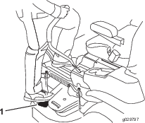
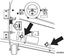
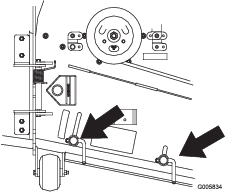
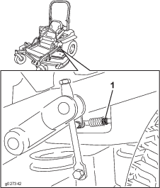
Adjusting the Motion-Control Linkage
The pump-control linkages are located on either side of the fuel tank, below the seat. Rotate the pump linkage with a 1/2 inch wrench for fine-tuning adjustments so that the machine does not move in neutral. Make any adjustments for neutral positioning only.
Warning
The engine must be running and the drive wheels must be turning, so the motion-control adjustment can be performed. Contact with moving parts or hot surfaces may cause personal injury.
Keep your fingers, hands, and clothing clear of rotating components and hot surfaces.
-
Prior to starting the engine, push the deck-lift pedal, remove the height-of-cut pin, and lower the deck to the ground.
-
Raise the rear of machine and support it with jack stands (or equivalent support) just high enough to allow the drive wheels to turn freely.
-
Remove the electrical connection from the seat safety switch, located under the bottom cushion of the seat.
Note: The switch is a part of the seat assembly.
-
Temporarily install a jumper wire across the terminals in the connector of the main wiring harness.
-
Start the engine.
Note: Engage the parking brake and move the motion-control levers out before starting the engine. You do not need to be in the seat because of the jumper wire being used. Run the engine at full throttle and release the brake.
-
Run the machine at least 5 minutes with the motion-control levers at full forward speed to bring the hydraulic fluid up to operating temperature.
-
Bring the motion-control levers into the NEUTRAL position.
-
Adjust the pump-control rod lengths by rotating the double nuts on the rod in the appropriate direction until the wheels slightly creep in reverse (Figure 87).
-
Move the motion-control levers to the REVERSE position, and while applying slight pressure to the lever, allow the reverse indicator springs to bring the levers back to neutral.
Note: The wheels must stop turning or slightly creep in reverse.
-
Shut off the machine.
-
Remove the jumper wire from wire harness and plug the connector into the seat switch.
-
Remove the jack stands.
-
Raise the deck and install the height-of-cut pin.
-
Check that the machine does not creep in neutral when you disengage the parking brakes.
Adjusting the Motion-Control Damper
You can adjust the top damper mounting bolt to obtain a more desired motion-control lever resistance. See Figure 88 for mounting options.
Adjusting the Motion-Control Neutral-Lock Pivot
You can adjust the flanged nut to obtain the desired motion-control lever resistance when you move them to the NEUTRAL-LOCK position. See Figure 89 for adjustment options.
-
Loosen the jam nut.
-
Tighten or loosen the flanged nut to the desired feel.
Note: For more resistance, tighten the flanged nut.
Note: For less resistance, loosen the flanged nut
-
Tighten the jam nut.
Hydraulic System Maintenance
Servicing the Hydraulic System
Hydraulic Fluid Type: Toro® HYPR-OIL ™ 500 hydraulic fluid or Mobil® 1 15W-50.
Important: Use the fluid specified. Other fluids could damage the hydraulic system.
Each Hydraulic System Fluid Capacity: 1.5 L (52 oz) per side with filter change
Checking the Hydraulic Fluid
-
Position the machine on a level surface.
-
Disengage the blade-control switch (PTO), move the motion-control levers to the NEUTRAL-LOCK position, and set the parking brake.
-
Shut off the engine, remove the key, and wait for all moving parts to stop before leaving the operating position.
-
Wait for the engine and hydraulic system to cool for 10 minutes.
Note: The fluid level on the dipstick is incorrect if you check the fluid when the machine is hot.
-
Move the seat forward.
-
Clean the area around the dipsticks of the hydraulic system reservoirs (Figure 90).
-
Remove 1 dipstick from the hydraulic reservoir (Figure 90).
-
Wipe the dipstick off and thread the dipstick into the reservoir.
-
Remove the dipstick and look at the end (Figure 90).
Note: If the fluid level is at the add mark, slowly pour only enough fluid into the hydraulic reservoir to raise the level to the full or H line.
Important: Do not overfill the hydraulic units with fluid, as damage may occur. Do not run the machine with the fluid below the add mark.
-
Install the dipstick.
-
Repeat procedure for the opposite dipstick.
Warning
Hydraulic fluid escaping under pressure can penetrate skin and cause injury.
-
If hydraulic fluid is injected into the skin, it must be surgically removed within a few hours by a doctor familiar with this type of injury. Gangrene may result if this is not done.
-
Keep your body and hands away from pin hole leaks or nozzles that eject high-pressure hydraulic fluid.
-
Use cardboard or paper to find hydraulic leaks.
-
Safely relieve all pressure in the hydraulic system before performing any work on the hydraulic system.
-
Make sure that all hydraulic-fluid hoses and lines are in good condition and that all hydraulic connections and fittings are tight before applying pressure to the hydraulic system.
-
Replacing the Hydraulic Filters and Hydraulic Fluid
To replace the hydraulic fluid, you need to remove the filters. Replace both at the same time; refer to Servicing the Hydraulic System for the oil specifications.
-
Disengage the blade-control switch (PTO), move the motion-control levers to the NEUTRAL-LOCK position, and set the parking brake.
-
Shut off the engine, remove the key, and wait for all moving parts to stop before leaving the operating position.
-
Raise the machine and support it with jack stands (Figure 91).
-
Remove both the mower belt and the pump-drive belt; refer to Replacing the Mower Belt and Replacing the Hydraulic-Pump Drive Belt.
Note: This prevents oil from getting on the belts.
-
Place a drain pan under the filter, remove the old filter, and wipe the surface clean (Figure 92).
-
Apply a thin coat of hydraulic fluid to the rubber gasket on the replacement filter (Figure 92).
-
Install the replacement hydraulic filter.
-
Install the pump-drive belt and the mower belt.
-
Remove the jack stands and lower the machine (Figure 91).
-
Add fluid to the hydraulic reservoir and check for any leaks.
-
Clean up any spilled fluid.
-
Start the engine and let it run for about 2 minutes to purge air from the system.
-
Shut off the engine and check for leaks.
-
Check the fluid level while the oil is cold.
-
If required, add fluid to the hydraulic reservoir.
Note: Do not overfill.
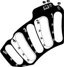
Leveling the Mower Deck
Setting Up the Machine
Note: Ensure that the mower deck is level before matching the height of cut (HOC).
-
Position the mower on a flat surface.
-
Disengage the blade-control switch (PTO), move the motion-control levers to the NEUTRAL-LOCK position, and set the parking brake.
-
Shut off the engine, remove the key, and wait for all moving parts to stop before leaving the operating position.
-
Check the pressure of the drive tires.
Note: Proper inflation pressure for the tires is 90 kPa (13 psi).
-
Position the mower deck to the 76mm (3inch) height-of-cut position.
Leveling the Deck
-
Position the mower on a flat surface.
-
Shut off the engine, wait for all moving parts to stop, remove the key, and engage the parking brake.
-
Check the pressure in the drive tires.
Note: Proper inflation pressure for the tires is 90 kPa (13 psi).
-
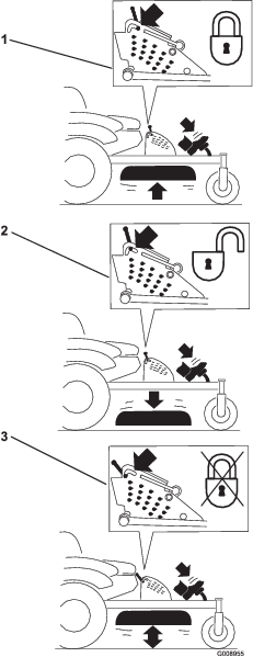
Position the transport lock in the latching position.
-
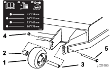
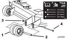
Push the deck lift pedal all the way forward and the deck will latch at the 14 cm (5-1/2 inch) transport position (Figure 93).
-
Insert the height-adjustment pin into the 7.6 cm (3 inch) height-of-cut location.
-
Release the transport lock and allow the deck to lower to the cutting height.
-
Raise the discharge chute.
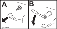
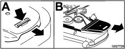
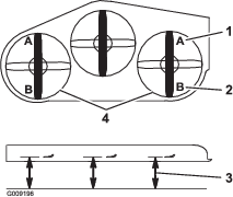
-
On both sides of the deck, measure from the level surface to the front tip of the blade (Postion A) as shown in Figure 94.
Note: The measurement should read 7.6 mm (3 inches)
-
If needed, loosen the flanged locknut on the side of the yoke and the jam nut on top.
-
Fine-tune the adjuster screw by turning it to get 7.6 mm (3 inch) height (Figure 95).
Note: To increase the height, turn the adjuster screw clockwise; to decrease the height, turn it counterclockwise.
-
If the front deck links do not have enough adjustment to achieve accurate cut height, loosen the 2 bolts at the bottom of the height-of-cut plate to adjust the single-point system (Figure 96).
-
If the deck is too low, tighten the single-point adjustment bolt by rotating it clockwise. If the deck is too high, loosen the single-point adjustment bolt by rotating it counterclockwise (Figure 97).
Note: Loosen or tighten the single-point adjustment bolt enough to move the height-of-cut plate mounting bolts at least 1/3 the length of the available travel in their slots. This regains some up-and-down adjustment on each of the 4 deck links.
-
Tighten the 2 bolts at the bottom of the height-of-cut plate (Figure 96).
Note: For most conditions, adjust the back blade tip 4 mm (1/4 inch) higher than the front.
-
Torque the 2 bolts to 37 to 45 N∙m (27 to 33 ft-lb).
-
On both sides of the deck, measure from the level surface to the back tip of the blade (position B) as shown in Figure 94.
Note: The measurement should read 8.3 cm (3-1/4 inches)
-
Fine-tune the adjuster screw by turning it to get 8.3 mm (3-1/4 inches) height (Figure 95).
Note: To increase the height, turn the adjustment nut clockwise; to decrease the height, turn it counterclockwise.
-
Measure until all 4 sides are the correct height.
-
Tighten all the nuts on the deck-lift-arm assemblies.
-
Lower the discharge chute.
Servicing the Cutting Blades
To ensure a superior quality of cut, keep the blades sharp. For convenient sharpening and replacement, keep extra blades on hand.
Warning
A worn or damaged blade can break, and a piece of the blade could be thrown at you or bystanders, resulting in serious personal injury or death.
-
Inspect the blades periodically for wear or damage.
-
Replace a worn or damaged blade.
Before Inspecting or Servicing the Blades
-
Park the machine on a level surface, Disengage the blade-control switch (PTO), and set the parking brake.
-
Turn the ignition key to off. Remove the key, and disconnect the spark plug wires from the spark plugs.
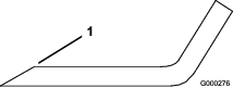
Inspecting the Blades
-
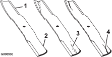
Inspect the cutting edges (Figure 98).
-
If the edges are not sharp or have nicks, remove and sharpen the blade; refer to Removing the Blades and Sharpening the Blades.
-
Inspect the blades, especially in the curved area.
-
If you notice any cracks, wear, or a slot forming in this area, immediately install a new blade (Figure 98).
Checking for Bent Blades
-
Disengage the blade-control switch (PTO), move the motion-control levers to the NEUTRAL-LOCK position, and set the parking brake.
-
Shut off the engine, remove the key, and wait for all moving parts to stop before leaving the operating position.
-
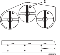
Rotate the blades until the ends face forward and backward (Figure 99).
-
Measure from a level surface to the cutting edge, position A, of the blades (Figure 99).
-
Rotate the opposite ends of the blades forward.
-
Measure from a level surface to the cutting edge of the blades at the same position as in step4.
Note: The difference between the dimensions obtained in steps 4 and5 must not exceed 3mm (1/8inch).
Note: If this dimension exceeds 3mm (1/8inch), the blade is bent and must be replaced.
Warning
A blade that is bent or damaged could break apart and could seriously injure or kill you or bystanders.
-
Always replace bent or damaged blade with a new blade.
-
Do not file or create sharp notches in the edges or surfaces of the blade.
-
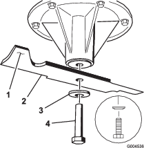
Removing the Blades
Replace a blade if it hits an object, if the blade is out of balance, or if the blade is bent. To ensure optimum performance and continued safety conformance of the machine, use genuine Toro replacement blades. Replacement blades made by other manufacturers may result in nonconformance with safety standards.
-
Hold the blade end using a rag or a thickly padded glove.
-
Remove the blade bolt, curved washer, and blade from the spindle shaft (Figure 100).
Sharpening the Blades
-
Use a file to sharpen the cutting edge at both ends of the blade (Figure 101).
Note: Maintain the original angle.
Note: The blade retains balance if you remove the same amount of material from both cutting edges.
-
Check the balance of the blade by putting it on a blade balancer (Figure 102).
Note: If the blade stays in a horizontal position, the blade is balanced and ready to use.

-
If the blade is not balanced, file some metal off the end of the sail area only (Figure 100).
-
Repeat this procedure until the blade is balanced.
Installing the Blades
-
Install the blade onto the spindle shaft (Figure 103).
Important: The curved part of the blade must point upward toward the inside of the mower to ensure proper cutting.
-
Install the spring disk and blade bolt (Figure 103).
Note: Install the spring-disk cone toward the bolt head.
-
Torque the blade bolt to 115 to 150 N∙m (85 to 110 ft-lb).
Removing the Mower Deck
Before servicing or removing the mower deck, lock out the spring-loaded deck arms.
Warning
Deck-lift-arm assemblies have stored energy. Removing the deck without releasing the stored energy can cause serious injury or death.
Do not attempt to disassemble the deck from the front frame without locking out the stored energy.
-
Shut off the engine, wait for all of the moving parts to stop, remove the key, and engage parking brake.
-
Remove the height-adjustment pin and lower the deck to the ground.
-
Place the height-adjustment pin in the 7.6 cm (3 inch) height-of-cut location.
Note: This locks the deck-lift arms in the lowest position so that when you remove the deck, the stored energy in the deck spring is released.
-
Remove the belt covers.
-
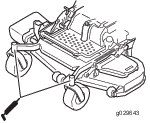
Lift the floor pan and insert a ratchet into the square hole in the deck idler (Figure 104).
-
Rotate the deck idler clockwise and remove the mower belt (Figure 104).
-
Remove and retain the hardware on both sides of the deck as shown in Figure 105.
-
Raise the deck struts and secure them in the up position.
-
Slide the deck out to the right side of the machine.
Replacing the Grass Deflector
Warning
An uncovered discharge opening could allow the lawn mower to throw objects at you or bystanders, resulting in serious injury. Also, contact with the blade could occur.
Do not operate the lawn mower unless you install a cover plate, mulch plate, grass deflector, or bagger.
-
Remove the locknut, bolt, spring, and spacer holding the deflector to the pivot brackets (Figure 106).
-
Remove the damaged or worn grass deflector (Figure 106).
-
Place the spacer and the spring onto grass deflector.
-
Place 1 J-hook end of the spring behind the deck edge.
Note: Make sure that 1 J-hook end of the spring is installed behind the deck edge before installing the bolt as shown in Figure 106.
-
Install the bolt and the nut.
-
Place 1 J-hook end of the spring around the grass deflector (Figure 106).
Important: The grass deflector must be able to rotate. Lift the deflector up to the full open position and ensure that it rotates into the fully down position.
Cleaning
Cleaning under the Mower
-
Disengage the blade-control switch (PTO), move the motion-control levers to the NEUTRAL-LOCK position, and set the parking brake.
-
Shut off the engine, remove the key, and wait for all moving parts to stop before leaving the operating position.
-
Raise the mower to the TRANSPORT position.
Cleaning the Suspension System
Note: Do not clean the shock assemblies with pressurized water (Figure 107).

Disposing of Waste
Engine oil, batteries, hydraulic fluid, and engine coolant are pollutants to the environment. Dispose of these according to your state and local regulations.