Setup
Preparing the Machine
-
Park the machine on a level surface.
-
Lower the cutting units.
-
Engage the parking brake.
-
Shut off the engine and remove the key.
-
Disconnect the battery; refer to your machine Operator’s Manual.
Warning
Incorrect battery cable routing could damage the machine and cables, causing sparks. Electrical sparks can cause the battery gasses to explode, resulting in personal injury.
Always disconnect the negative (black) battery cable before disconnecting the positive (red) cable.
Installing the Lights
Parts needed for this procedure:
| Right headlight mount | 1 |
| Left headlight mount | 1 |
| Right tail light mount | 1 |
| Left tail light mount | 1 |
| Right headlight assembly | 1 |
| Left headlight assembly | 1 |
| Tail light assembly | 2 |
| Tail light extension bracket | 2 |
| Flange nut (3/8 inch) | 10 |
| Hex-head bolt (3/8 x 1 inch) | 1 |
| Hex-head bolt (5/16 x 1 inch) | 4 |
| Hex-head bolt (5/16 x 3/4 inch) | 4 |
| Hex-head bolt (3/8 x 3/4 inch) | 8 |
| Flange nut (5/16 inch) | 4 |
Installing the Headlights
Note: The left and right lights and mounts are different. Ensure that each light and mount is installed on the appropriate side.
-
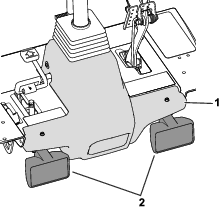
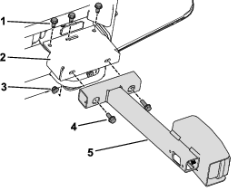
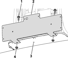
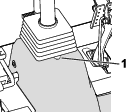
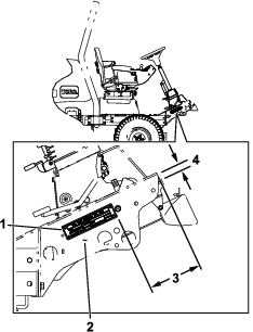
Unplug the shroud headlight connectors and remove the fasteners that secure the platform shroud to the machine frame (Figure 1).
Retain the fasteners to secure the shroud to the machine.
-
Remove the shroud from the frame.
-
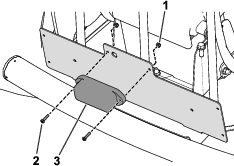
Use 5 hex-head bolts (3/8 x 3/4 inch) and 5 flange nuts (3/8 inch) to secure the left headlight mount to the left floor bracket (Figure 2).
-
Use 4 hex-head bolts (3/8 x 3/4 inch) and 4 flange nuts (3/8 inch) to secure the right headlight mount to the right floor bracket (Figure 2).
-
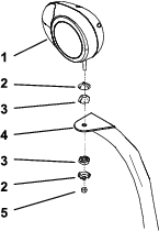
Fasten the left and right headlights to the headlight mounts (Figure 3) with the fasteners supplied with the lights.
Note: Ensure that the turn-signal lens on the headlight is positioned toward the outside of the traction unit.
-
Tighten the locknut to firmly hold the headlight assembly to the headlight bracket.
Note: Do not overtighten the locknut.
Installing the Tail Lights
Note: The left and right tail light mounts are different. Ensure that each mount is installed on the appropriate side.
-
Raise the hood; refer to your machine Operator’s Manual.
-
Install the light mounts; refer to the following steps based on your machine:
-
For Model No. 03674 (Reelmaster 5010-H), 03675 (Reelmaster 5410), and 03676 (Reelmaster 5510) machines:
-
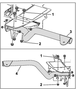
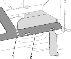
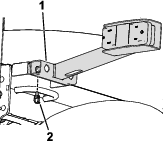
Remove the bolts from the frame rail on each side of the machine (Figure 4).
-
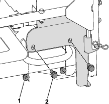
Use the previously removed bolts to secure the tail light extension brackets to the frame rail (Figure 5).
-
Use 4 bolts (5/16 x 3/4 inch) and 4 nuts (5/16 inch) to secure the tail light mounts to the extension brackets (Figure 5).
-
-
For all other machines:
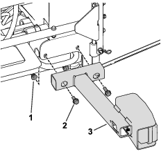
Note: Older machines may have a chassis leg that extends in front of the radiator-frame fasteners. Remove the chassis leg, then file and paint over the new chassis end (Figure 6).
-
-
Mount the tail lights to the light mounts with the bolts and nuts included with each light.
Installing the Horn
Parts needed for this procedure:
| Horn | 1 |
| Horn bracket | 1 |
| Hex-head bolt (3/8 x 1 inch) | 1 |
| Flange nut (3/8 inch) | 1 |
-
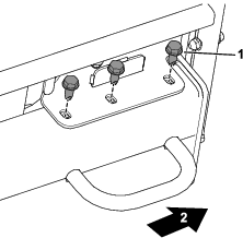
Use the existing hardware on the horn to attach the horn to the horn bracket.
-
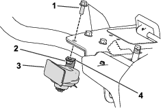
Use a hex-head bolt (3/8 x 1 inch) and a flange nut (3/8 inch) to secure the horn and horn bracket to the right floor bracket (Figure 9).
Installing the Rear Light Plate
Parts needed for this procedure:
| Light mount | 1 |
| Light plate | 1 |
| Flange nut (3/8 inch) | 2 |
| Locknut (#10) | 2 |
| Flange bolt (3/8 inch) | 2 |
| Screw (#10) | 2 |
-
Open the rear screen; refer to your machine Operator’s Manual.
-
Align the light mount to the bottom of the machine frame.
-
Mark the location of the light mount holes on the frame, remove the light plate, and drill 2 holes (3/8 inch) into the frame.
-
Use 2 flange bolts (3/8 inch) and 2 flange nuts (3/8 inch) to secure the light mount to the machine frame.
-
Use 2 screws (#10) and 2 locknuts (#10) to secure the light plate to the light mount.
-
Close the rear screen.
Installing the Column-Bracket Assembly onto the Steering Column
Parts needed for this procedure:
| Column mount bracket | 1 |
| Flasher module | 1 |
| On-Off-On rocker switch | 1 |
| Beacon switch | 1 |
| Paddle switch | 1 |
| Horn switch | 1 |
| Horn button | 1 |
| Hex socket button-head screw | 1 |
| Speed nut | 2 |
| Steering-column bracket | 1 |
| Carriage bolt (3/8 x 1inch) | 2 |
| Flange nut (3/8 inch) | 2 |
-
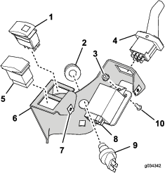
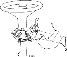
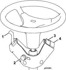
Install the components as shown in Figure 12.
-
Install the column-mount bracket onto the steering column with the mounting bracket, 2 carriage bolts, and 2 flange nuts (Figure 13).
Important: Ensure that the top of the steering-column bracket is 21 mm (0.83 inch) below the top of the steering column.
Important: Torque the fasteners to 19 to 24 N∙m (14 to 18 ft-lb). Do not overtighten the carriage bolts; otherwise, you may deform the steering-column bracket.
Installing the Wire Harness
Parts needed for this procedure:
| Wire harness | 1 |
| Adapter harness (long) | 1 |
| Tie clip | 1 |
| Adapter harness (short) | 2 |
| Fuse block mount | 1 |
| Flange nut (5/16 inch) | 2 |
| Locknut (M6) | 2 |
| Flange bolt (M6) | 2 |
| Flange bolt (5/16 x 1 inch) | 2 |
Wire Harness Overview
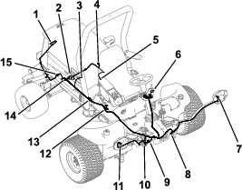
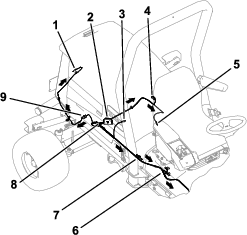
Use the following instructions and illustrations to route and connect the wire harness. Refer to Figure 14 for an overview of the wire harness.
Routing the Wire Harness to the Rear of the Machine
-
Raise the hood; refer to your machine Operator’s Manual.
-
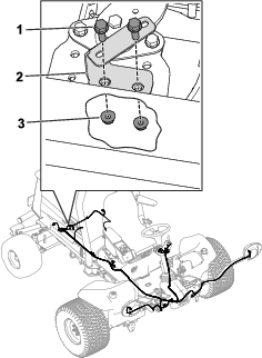
Use 2 flange bolts (5/16 x 1 inch) and 2 flange nuts (5/16 inch) to secure the fuse block mount to the engine mount frame on the right side of the machine (Figure 15).
-
Use 2 flange bolts (M6) and 2 locknuts (M6) to secure the fuse block to the fuse block mount (Figure 16).
-
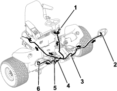
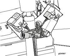
Route the wire harness to the left side of the machine as shown in Figure 17.
-
Connect the engine ground leg of the wire harness to the ground block (Figure 17).
-
Connect the wire harness to the right and left tail lights (Figure 17).
-
Insert a tie clip into the rear hole of the right tail light (Figure 18).
-
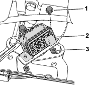
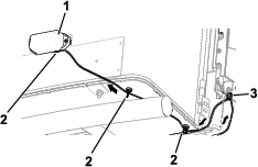
Use the long adapter harness to connect the wire harness to the registration plate lights. (Figure 17 and Figure 19).
Refer to Figure 19 for the appropriate magnet-tie-mount location on the machine. Place 1 magnet on the inside surface of the license plate mount. Route the adapter harness through the tie clip that you installed in the previous step.
-
Continue to route the wire harness along the right frame rail (Figure 17).
-
Connect the ring terminal to the starter (Figure 17).
-
Connect the wire harness to the beacon (Figure 17).
-
Connect the wire harness to the neutral switch (Figure 17).
Routing the Wire Harness to the Front of the Machine
-
Route the front end of the wire harness under the operator platform to the front of the machine (Figure 20).
-
Thread each harness connector through the appropriate headlight bracket and connect it to the headlight (Figure 20).
Non-hybrid machines: Use the short adapter harnesses to connect the wire harness to each headlight.
-
Plug the wire harness lead with the 2 connectors into the horn (Figure 20).
-
Position the platform shroud on top of the frame.
-
Plug the light-kit wire harness connectors into the shroud headlights (Figure 20).
-
Cut out a U-shaped notch on the shroud (Figure 21).
Note: The U-shaped notch allows you to route the wire harness up towards the switches on the steering column.
-
Secure the shroud to the frame with the fasteners that you previously removed.
-
Route the wire harness to the column-bracket assembly on the steering column (Figure 20).
-
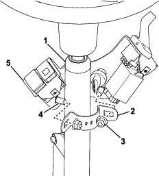
Plug the connectors into the flasher module, horn, turn signal, and hazard switches (Figure 22).
-
Install the cover onto the column-bracket assembly with 2 hex socket button-head screws as shown in Figure 23
Installing the Signs and Serial Plate
Parts needed for this procedure:
| Sign | 3 |
| Serial plate | 1 |
| Speed plate | 1 |
| U-bolt | 1 |
| Flange nut (3/8 inch) | 2 |
-
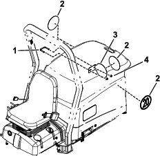
Adhere a sign on both sides of the machine (Figure 24).
-
Use a U-bolt and 2 flange nuts (3/8 inch) to secure the speed plate to the left side of the roll bar (Figure 24).
-
Adhere a sign to the speed plate (Figure 24).
-
Hold the serial plate on the right side of the machine, 6 mm (1/4 inch) above the bottom edge (Figure 25). Use the serial plate as a template and drill 4 holes (3 mm or 1/8 inch).
-
Secure the serial plate using 4 rivets.
-
Stamp the serial number to the frame, near the serial plate (Figure 25).
Note: Use 7 mm (1/4 inch) or larger text.
Connecting the Battery
Connect the battery; refer to your machine Operator’s Manual.
Warning
Incorrect battery cable routing could damage the sprayer and cables, causing sparks. Electrical sparks can cause the battery gasses to explode, resulting in personal injury.
Always connect the positive (red) battery cable before connecting the negative (black) cable.
Operation
Controls
Aiming the Headlights
-
Loosen the mounting nuts and position each headlight so that it points straight ahead.
-
Tighten each mounting nut just enough to hold the headlight in position.
-
Place a flat piece of sheet metal over the face of the headlight.
-
Mount a magnetic protractor onto the plate.
-
While holding the assembly in place, carefully tilt the headlight downward 3 degrees, then tighten the nut.
-
Repeat the procedure for the other headlight.