Introduction

This rotary-blade lawn cutting deck is mounted to a ride-on machine and is intended to be used by professional, hired operators in commercial applications. It is primarily designed for cutting grass on well-maintained lawns in parks, sports fields, and on commercial grounds.

Read this information carefully to learn how to operate and maintain your product properly and to avoid injury and product damage. You are responsible for operating the product properly and safely

Visit www.Toro.com for product safety and operation training materials, accessory information, help finding a dealer, or to register your product.

Whenever you need service, genuine Toro parts, or additional information, contact an Authorized Service Dealer or Toro Customer Service and have the model and serial numbers of your product ready. The model and serial numbers are stamped into a plate that is mounted on the cutting unit housing. Write the numbers in the space provided.

This manual identifies potential hazards and has safety messages identified by the safety-alert symbol (Figure 1), which signals a hazard that may cause serious injury or death if you do not follow the recommended precautions.

g000502

This manual uses 2 words to highlight information. Important calls attention to special mechanical information and Note emphasizes general information worthy of special attention.

Model 30456 complies with all relevant European directives when the CE Kit (Model No. 30658) is installed on the cutting unit. Model number 30353 requires CE Kit model number 30685; 30457 requires CE Kit 30683; 30481 requires CE Kit 30679. For additional details, see the separate product specific Declaration of Conformity (DOC) sheet.

Warning

CALIFORNIA

Proposition 65 Warning

Use of this product may cause exposure to chemicals known to the State of California to cause cancer, birth defects, or other reproductive harm.

Safety

This machine has been designed in accordance with ANSI B71.4-2017 and EN ISO 5395:2013.

General Safety

This product is capable of amputating hands and feet and of throwing objects. Always follow all safety instructions to avoid serious personal injury.

Using this product for purposes other than its intended use could prove dangerous to you and bystanders.

  • Read and understand the contents of this Operator’s Manual before starting the engine.

  • Do not put your hands or feet near moving components of the machine.

  • Do not operate the machine without all guards and other safety protective devices in place and working on the machine.

  • Keep clear of any discharge opening. Keep bystanders and pets a safe distance away from the machine.

  • Keep children out of the operating area. Never allow children to operate the machine.

  • Park the machine on a level surface, lower the cutting units, disengage the drives, engage the parking brake (if provided), shut off the engine, and remove the key before leaving the operator's position for any reason.

Improperly using or maintaining this machine can result in injury. To reduce the potential for injury, comply with these safety instructions and always pay attention to the safety-alert symbol Graphic
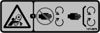
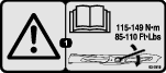
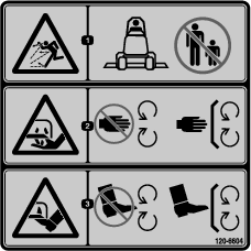
, which means Caution, Warning, or Danger—personal safety instruction. Failure to comply with these instructions may result in personal injury or death.

You can find additional safety information where needed throughout this Operator’s Manual.

Safe Operating Practices

  • Never allow children or untrained people to operate or service the machine. Local regulations may restrict the age of the operator. The owner is responsible for training all operators and mechanics.

  • Become familiar with the safe operation of the equipment, operator controls, and safety signs.

  • The owner/operator can prevent and is responsible for accidents that may cause personal injury or property damage.

  • Wear appropriate clothing, including eye protection; substantial, slip-resistant footwear; long pants, and hearing protection. Tie back long hair and do not wear loose jewelry.

  • Inspect the area where the equipment is to be used and remove all objects, such as rocks, toys, and wire, that the machine can throw.

  • Check that operator's presence controls, safety switches, and shields are attached and functioning properly. Do not operate the machine unless they are functioning properly.

  • Stop the machine, remove the key, and wait for all moving parts to stop before inspecting the attachment after striking an object or if there is an abnormal vibration in the machine. Make all necessary repairs before resuming operation.

  • Keep your hands and feet away from the cutting units.

  • Keep all parts in good working condition and all hardware tightened. Replace all worn or damaged decals.

  • A worn or damaged blade can break, and a piece of the blade could be thrown toward you or bystanders, resulting in serious personal injury or death.

  • Inspect the blade periodically for wear or damage.

  • Use care when checking the blades. Wrap the blades or wear gloves, and use caution when servicing the blades. Only replace or sharpen the blades; never straighten or weld them.

  • On multi-bladed machines, take care as rotating 1 blade can cause other blades to rotate.

  • Check the blade mounting bolts frequently to be sure that they are tightened to specification.

Safety and Instructional Decals

Graphic

Safety decals and instructions are easily visible to the operator and are located near any area of potential danger. Replace any decal that is damaged or missing.

decal93-6687
decal93-6696
decal93-6697
decal93-7818
decal107-2908
decal107-2916
decal112-1461
decal117-4979
decal120-6604
decal133-8061

Setup

Note: Determine the left and right sides of the machine from the normal operating position.

Removing the Existing Cutting Unit (If Equipped)

  1. Park the machine on a level surface with the cutting unit in the fully raised position. Shut off the engine, engage the parking brake, and remove the key.

    Note: When the cutting unit is in the raised position, the pull-link torsion spring tension (Figure 2) is reduced, making it much easier to disconnect the pull links from the machine.

    g017279
  2. Disconnect the pull link from each side of the machine (Figure 2).

    Caution

    The pull link torsion springs may cause some rotation of the pull links during the removal process.

    Use caution when disconnecting the pull links.

    1. Remove the shoulder screw that secures the retainer pin to the carrier frame (Figure 2).

    2. Carefully slide the retainer pin from the carrier frame and the pull link (Figure 2).

  3. Note the location of the HOC pin in the HOC bracket for assembly purposes (Figure 3). Remove the HOC pin from the HOC bracket.

    g017278
  4. Start the engine, lower the cutting unit to the ground, shut off the engine, and remove the key.

    Note: Lowering the cutting unit onto furniture dollies aids in removing the cutting unit.

    Warning

    If the engine is started and the PTO driveshaft is allowed to rotate, serious personal injury and machine damage could result.

    • When the driveshaft is disconnected from the cutting unit, do not start the engine and engage the PTO switch.

    • If the driveshaft is disconnected from the mower, remove fuse F1 (15 A) from the fuse block to prevent unintentional engagement of the PTO clutch.

  5. Disconnect the end yoke of the PTO driveshaft from the cutting unit gearbox shaft:

    1. Remove the roll pin from the end yoke and the gearbox shaft (Figure 4).

      g012230
    2. Loosen the 2 capscrews and locknuts (Figure 4).

    3. Slide the drive shaft end yoke from the gearbox shaft.

      Note: Raise and tie the drive shaft to the frame.

  6. Remove the 4 ring pins and clevis pins that secure the lift chains to the adjustment clevises on the mower (Figure 2).

  7. Slide the cutting unit away from the machine.

    Note: You may have to elevate the front of the traction unit to move the cutting unit away from the machine.

Installing the New Cutting Unit

  1. Slide the new cutting unit under the carrier frame of the machine.

  2. Install the 4 clevis pins and ring pins to secure the cutting unit lift chains to the adjustment clevises on the mower (Figure 2).

  3. Connect the end yoke of the PTO drive shaft to the cutting unit gearbox; refer to the following steps:

    1. Align the spline and roll pin holes of the drive shaft yoke with the gear box shaft.

    2. Slide the PTO drive shaft end yoke onto the gearbox shaft.

    3. Secure the end yoke of the PTO drive shaft to the gearbox shaft with the roll pin (Figure 4).

    4. Tighten the locknuts to secure the end yoke to the gearbox shaft (Figure 4). Torque the locknuts to 20 to 25 N∙m (175 to 225 in-lb).

  4. Start the engine and fully raise the cutting unit. Shut off the engine and remove the key from the ignition switch.

    Note: Place a wood block or similar shim under each link to hold it in the raised position.

    Caution

    The pull link torsion springs may cause some rotation of the pull links during installation.

    Use caution when connecting the pull links to the machine.

  5. Align the pull link to the carrier frame and attach the link with the retainer pin (Figure 2). Secure the retainer pin to the frame with the shoulder screw (Figure 2).

  6. Install the HOC pin into the HOC bracket at the desired height of cut (Figure 3).

  7. Lubricate the PTO drive shaft grease fittings.

  8. Install the F1 fuse (15 A) into the fuse block.

Leveling the Cutting Unit

Leveling Side-to-Side

  1. Position the machine on a level surface on the shop floor and lower the cutting unit.

  2. Move the throttle lever to the SLOW position, shut off the engine, engage the parking brake, and remove the key.

  3. Set the cutting unit to a 127 mm (5 inch) height of cut.

  4. Check and adjust the front and rear traction-unit tire pressure; refer to Operator’s Manual for pressure specifications.

  5. Check for bent blades; refer to Checking for Bent Blades.

  6. Rotate the blade on each spindle until the ends face forward and backward.

  7. Measure from the floor to the front tip of the cutting edge.

  8. Adjust the jam nuts securing the mower yokes/chains to the mower until the cutting unit is level (Figure 5).

    g004497

Leveling Front-to-Back

Cutting unit pitch is the difference in height of cut from the front-to-back of the blade plane. A blade pitch of approximately 8 to 11 mm (5/16 to 7/16 inch) is recommended (i.e., the back of the blade plane is 8 to 11 mm (5/16 to 7/16 inch) higher than the front).

  1. Set the cutting unit to the desired height-of-cut, move the throttle lever to the SLOW position, shut off the engine, engage the parking brake, and remove the key.

  2. Rotate the center blade so that it points straight forward.

  3. Using a short ruler, measure from the floor to the front tip of the blade.

  4. Rotate the same blade tip to the rear and measure from the floor to the tip of the blade at the rear of the cutting unit.

  5. Subtract the front dimension from the rear dimension to calculate the blade pitch.

  6. Adjust the jam nuts securing the rear mower yokes/chains (Figure 5) to raise the rear of the cutting unit so that the blade pitch is set to 8 to 11 mm (5/16 to 7/16 inch).

Operation

Note: Determine the left and right sides of the machine from the normal operating position.

Adjustments

Adjusting the Height-of-Cut

The height-of-cut is adjusted from 2.5 to 15.8 cm (1 to 6 inches) in 6 mm (1/4 inch) increments by relocating the stop pin into different hole locations.

  1. With the engine running, push back on the cutting unit lift switch until the cutting unit is fully raised and release the switch immediately (Figure 6).

    g014263
  2. To adjust the height of cut, rotate the stop pin until the nub on it lines up with the slots in the holes in the height-of-cut bracket and remove it (Figure 6).

  3. Select a hole in the height-of-cut bracket corresponding to the height-of-cut desired, insert the pin, and rotate it down to lock it in place (Figure 6).

    Note: There are 4 rows of hole positions (Figure 6). The top row gives you the height of cut listed above the pin. The second row down gives you the height listed plus 6 mm (1/4 inch). The third row down gives you the height listed plus 12 mm (1/2 inch). The bottom row gives you the height listed plus 18 mm (3/4 inch). For the 15.8 cm (6 inch) position there is only 1 hole, located in the second row. This does not add 6 mm (1/4 inch) to the 15.8 cm (6 inch) position.

  4. Adjust the anti-scalp rollers and skids as required.

Adjusting the Skid(s)

Mount the skids in the lower position when operating in height of cuts higher than 64 mm (2-1/2 inches) and in the higher position when operating in height of cuts lower than 64 mm (2-1/2 inches).

Note: On Guardian® mowers, when the skids become worn, you can switch the skid to the opposite sides of the cutting unit, flipping them over. This will allow you to use the skids longer before replacing them.

  1. Disengage the PTO and engagethe parking brake.

  2. Move the throttle lever to the SLOW position, shut off the engine, remove the key, and wait for all moving parts to stop before leaving the operating position.

  3. Loosen the screw at the front of each skid. There are 2 skids on Guardian mowers and 1 skid on side-discharge cutting units (Figure 7).

    g004479
  4. Remove the flange-head bolts and nuts from each skid.

  5. Move each skid to the desired position and secure them with the flange-head bolts and nuts.

    Note: Only use the top or center sets of holes to adjust the skids. The bottom holes are used when switching sides on a Guardian mower, at which time they become the top holes on the other side of the cutting unit.

  6. Torque the screw at the front of each skid to 9 to 11 N-m (80 to 100 in-lb).

Adjusting the Rear Anti-Scalp Rollers

Whenever you change the height-of-cut, adjust the height of the rear anti-scalp rollers.

  1. Disengage the PTO, release the traction pedal, and engage the parking brake.

  2. Move the throttle lever to the SLOW position, shut off the engine, remove the key, and wait for all moving parts to stop before leaving the operating position.

  3. After adjusting the height-of-cut, adjust the rollers by removing the flange nut, bushing, spacer, and bolt (Figure 8).

    g004483
  4. Select a hole so the anti-scalp roller is positioned to the nearest corresponding height-of-cut desired (Figure 9).

    g004658
  5. Install the flange nut bushing, spacer, and bolt. Torque to 54 to 61 N∙m (40 to 45 ft-lb) (Figure 8).

Adjusting the Rollers

Mount the rollers in the lower position when operating in height of cuts higher than 64 mm (2-1/2 inches) and in the higher position when operating in height of cuts lower than 64 mm (2-1/2 inches).

  1. Disengage the PTO, release the traction pedal, and engage the parking brake.

  2. Move the throttle lever to the SLOW position, shut off the engine, remove the key, and wait for all moving parts to stop before leaving the operating position.

  3. Raise the front of the machine and support it on jack stands.

  4. Remove the fasteners securing each roller on your cutting unit and move the rollers up or down as desired; refer to Figure 10 through Figure 14 as applicable for your cutting unit.

    Note: You may need to remove the front roller for certain Groundsmaster 7200 and 7210 models.

    g004487
    g004926
    g004923
    g004925
    g004924
  5. Install the fasteners as illustrated.

Operating Tips

Fast Throttle Setting/Ground Speed

To maintain enough power for the machine and deck while mowing, operate the engine at the fast throttle position and adjust your ground speed for conditions. Decrease the ground speed as the load on the cutting blades increases. Increase the ground speed as the load on the blades decreases.

Mowing Direction

Alternate mowing direction to avoid making ruts in the turf over time. This also helps disperse clippings which enhances decomposition and fertilization.

Cutting Speed

To improve cut quality, use a slower ground speed.

Avoid Cutting Too Low

If the cutting width of the cutting unit is wider than the mower you previously used, raise the cutting height to ensure that uneven turf is not cut too short.

Select the Proper Height-of-Cut Setting to Suit Conditions

Remove approximately 1 inch (25 mm) or no more than 1/3 of the grass blade when cutting. In exceptionally lush and dense grass, you may have to slow down the forward speed and/or raise the height-of-cut to the next higher setting.

Important: If cutting more than 1/3 of the grass blade off, or in sparse long grass or dry conditions, the use of flat sail blades is recommended to reduce air-borne chaff, debris, and deck drive component strain.

Long Grass

If the grass is ever allowed to grow slightly longer than normal, or if it contains a high degree of moisture, raise the cutting height higher than usual and cut the grass at this setting. Then cut the grass again using the lower, normal setting.

Keep the Cutting Unit Clean

Clean clippings and dirt from the underside of the cutting unit after each use. If grass and dirt build up inside the cutting unit, cutting quality will eventually become unsatisfactory.

To reduce the risk of fire hazard, keep the engine, muffler, battery compartment, parking brake, cutting units, and fuel storage compartment free of grass, leaves, or excessive grease. Clean up any spilled oil or fuel.

Blade Maintenance

Maintain a sharp blade throughout the cutting season because a sharp blade cuts cleanly without tearing or shredding the grass blades. Tearing and shredding turns grass brown at the edges, which slows growth and increases the chance of disease. Check the blades daily for sharpness, and for any wear or damage. Sharpen the blades as necessary. If a blade is damaged or worn, replace it immediately with a genuine Toro replacement blade. Refer to Servicing the Cutting Blades.

Maintenance

Note: Determine the left and right sides of the machine from the normal operating position.

Warning

If you raise the machine using only a jack to support it while you work under the cutting unit, the jack could tip, causing the mower deck to fall, crushing you or bystanders.

Always secure the machine with at least 2 jack stands when you have the mower deck raised.

Caution

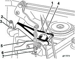
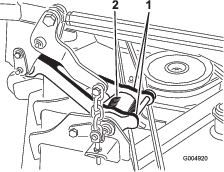
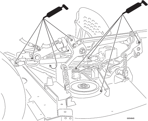
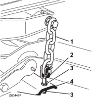
On the top of the cutting unit are 2 links that connect them to the frame. Connected to these links are torsion spring that are under tension (Figure 15). If you disconnect the link, the stored energy in the torsion spring will be released and could cause the links to move, damaging your hands or fingers.

Be careful when removing the cutting unit from the frame and secure the links before disconnecting them from the frame.

g004920

Recommended Maintenance Schedule(s)

Maintenance Service IntervalMaintenance Procedure
After the first 50 hours
  • Check the condition of the blade drive belts on the cutting unit.
  • Before each use or daily
  • Check the cutting unit blades.
  • Clean the cutting unit.
  • Every 50 hours
  • Grease the bearing and bushing grease fittings.
  • Lubrication

    Greasing the Bearings and Bushings

    Maintenance Service IntervalMaintenance Procedure
    Every 50 hours
  • Grease the bearing and bushing grease fittings.
  • The machine has grease fittings that must be lubricated regularly with No. 2 lithium grease. Bearings and bushings must be lubricated daily when operating conditions are extremely dusty and dirty. Dusty and dirty operating conditions could cause dirt to get into the bearings and bushings, resulting in accelerated wear. Lubricate the grease fittings immediately after every washing, regardless of interval specified.

    1. Wipe the grease fittings clean so foreign matter cannot be forced into the bearing or bushing.

    2. Pump grease into the fittings.

    3. Wipe off excess grease.

    g004645
    g004646

    Note: Bearing life can be negatively affected by improper wash down procedures. Do not wash the unit when it is still hot and avoid directing high-pressure or high volume spray at the bearings or seals.

    Replacing the Blade Drive Belts

    Maintenance Service IntervalMaintenance Procedure
    After the first 50 hours
  • Check the condition of the blade drive belts on the cutting unit.
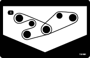
  • The blade drive belts, tensioned by the spring loaded idler pulleys, are very durable. However, after many hours of use, the belts will show signs of wear. Signs of a worn belt include squealing when the belt is rotating, blades slipping when cutting grass, poor quality of cut, frayed edges, and burn marks and cracks. Replace the belts if any of these conditions are evident.

    1. Lower the cutting unit to the 1 inch height of cut setting, move the throttle lever to the SLOW position, shut off the engine, engage the parking brake, and remove the key.

    2. Remove the belt covers from the top of the cutting unit and set the covers aside.

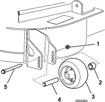
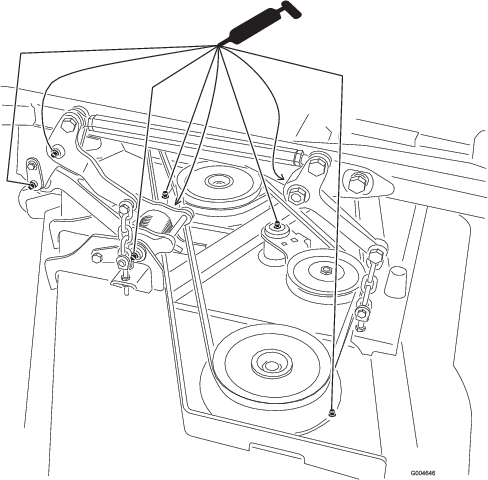
    3. Using a breaker bar or similar tool, move the idler pulley for the top belt (Figure 18) away from the top drive belt to release the belt tension and allow the belt to be slipped off the pulleys.

      g004486
    4. Route a new belt around the gearbox pulley, bottom spindle pulleys, and idler pulley assembly as shown in Figure 18.

    5. Route a new belt around the top spindle pulleys and idler pulley assembly as shown in Figure 18.

    6. Grease all mower and cutting unit drive grease points.

    7. Install the belt covers.

    Servicing the Cutting Blades

    Maintain sharp blades throughout the cutting season because sharp blades cut cleanly without tearing or shredding the grass blades. Tearing and shredding turns grass brown at the edges, which slows growth and increases the chance of disease.

    Check the blades daily for sharpness, and for any wear or damage. Sharpen the blades as necessary. If a blade is damaged or worn, replace it immediately with a genuine Toro replacement blade.

    Danger

    A worn or damaged blade can break, and a piece of the blade could be thrown toward you or bystanders, resulting in serious personal injury or death.

    • Inspect the blade periodically for wear or damage.

    • Replace a worn or damaged blade.

    Inspect and check the blades every 8 hours.

    Inspecting the Blades

    Maintenance Service IntervalMaintenance Procedure
    Before each use or daily
  • Check the cutting unit blades.
    1. Disengage the PTO, release the traction pedal, and engage the parking brake.

    2. Move the throttle lever to the SLOW position, shut off the engine, remove the key, and wait for all moving parts to stop before leaving the operating position.

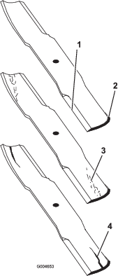
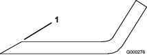
    3. Inspect the cutting edges (Figure 19). If the edges are not sharp or have nicks, remove and sharpen the blades. Refer to Sharpening the Blades (Sharpening the Blades).

    4. Inspect the blades, especially the sail area (Figure 19). If you notice any damage, wear, or a slot forming in this area (Figure 19), immediately install a new blade.

      Danger

      If you allow the blade to wear, a slot will form between the sail and flat part of the blade. Eventually a piece of the blade may break off and be thrown from under the housing, possibly resulting in serious injury to you or bystanders.

      • Inspect the blade periodically for wear or damage.

      • Never try to straighten a blade that is bent or weld a broken or cracked blade.

      • Replace a worn or damaged blade.

      g004653

    Checking for Bent Blades

    1. Disengage the PTO, release the traction pedal, and engage the parking brake.

    2. Move the throttle lever to the SLOW position, shut off the engine, remove the key, and wait for all moving parts to stop before leaving the operating position.

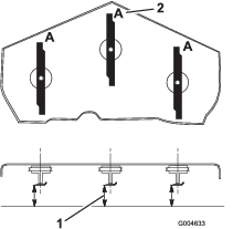
    3. Rotate the blades until the ends face forward and backward (Figure 20). Measure from a level surface to the cutting edge, position A, of the blades (Figure 20). Note this dimension.

      g004633
    4. Rotate the opposite ends of the blades forward.

    5. Measure from a level surface to the cutting edge of the blades at the same position as in step 3 above. The difference between the dimensions obtained in steps 3 and 4 must not exceed 3 mm (1/8 inch). If this dimension exceeds 3 mm (1/8 inch), the blade is bent and must be replaced; refer to Removing the Blades and Installing the Blades.

      Warning

      A blade that is bent or damaged could break apart and could seriously injure or kill you or bystanders.

      • Always replace bent or damaged blade with a new blade.

      • Never file or create sharp notches in the edges or surfaces of blade.

    Removing the Blades

    Blades must be replaced if a solid object is hit, if the blade is out of balance or is bent. To ensure optimum performance and continued safety conformance of the machine, use genuine Toro replacement blades. Replacement blades made by other manufacturers may result in non-conformance with safety standards.

    Warning

    Contact with a sharp blade can cause serious injury.

    Wear gloves or wrap sharp edges of the blade with a rag.

    1. Disengage the PTO, release the traction pedal, and engage the parking brake.

    2. Move the throttle lever to the SLOW position, shut off the engine, remove the key, and wait for all moving parts to stop before leaving the operating position.

    3. Hold the blade end using a rag or thickly-padded glove.

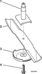
    4. Remove the blade bolt, anti-scalp plate, and blade from the spindle shaft; refer to Figure 23 in Installing the Blades.

    Sharpening the Blades

    Warning

    When sharpening blade, pieces of blade could be thrown and cause serious injury.

    Wear proper eye protection when sharpening blades.

    1. Sharpen the cutting edge at both ends of the blade (Figure 21). Maintain the original angle. The blade retains its balance if the same amount of material is removed from both cutting edges.

      g000276
    2. Check the balance of the blade by putting it on a blade balancer (Figure 22). If the blade stays in a horizontal position, the blade is balanced and can be used. If the blade is not balanced, file some metal off the end of the sail area only (Figure 23). Repeat this procedure until the blade is balanced.

      g000277

    Installing the Blades

    1. Install the blade onto the spindle shaft (Figure 23).

      Important: The curved part of the blade must point upward toward the inside of the cutting unit to ensure proper cutting.

    2. Install the anti-scalp plate and blade bolt (Figure 23).

      g004480
    3. Torque the blade bolt to 115-150 N⋅m (85-110 ft-lb).

    Correcting Cutting Unit Mismatch

    If the cut is uneven across the cutting unit swath, correct it as follows:

    1. Position the machine on a level surface.

    2. Set the cutting unit to the desired height of cut, move the throttle lever to the SLOW position, shut off the engine, engage the parking brake, and remove the key.

    3. Check and adjust front and rear traction-unit tire pressure; refer to the traction unit Operator’s Manual.

    4. Check for bent blades.

    5. Remove the covers from the top of the cutting units.

    6. Rotate the blade on each spindle until the ends face forward and backward.

    7. Measure from the floor to the front tip of the cutting edge.

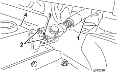
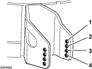
    8. Adjust the jam nuts securing the cutting unit yokes/chains to the mower until the cutting unit is level (Figure 24).

      g004497

    Replacing the Grass Deflector

    Warning

    An uncovered discharge opening allows the machine to throw objects toward you or bystanders, which can result in serious injury. Contact with the blade can also occur.

    • Never operate the machine without a mulch kit or grass deflector installed.

    • Ensure that the grass deflector is lowered.

    1. Lower the cutting unit to the ground, move the throttle lever to the SLOW position, shut off the engine, engage the parking brake, and remove the key.

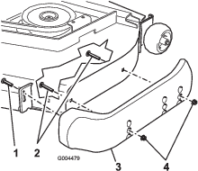
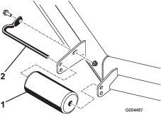
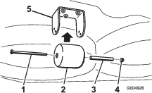
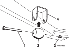
    2. Remove the locknut, bolt, spring and spacer holding the deflector to the pivot brackets (Figure 25). Remove damaged or worn grass deflector.

      g004485
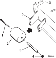
    3. Place the spacer and spring between the replacement grass deflector brackets (Figure 25). Place the left hand J hook end of the spring behind the cutting unit edge.

      Note: Ensure that the left-hand hook end of the spring is installed behind the cutting unit edge before installing the bolt as shown in Figure 25.

    4. Install the bolt and nut. Place the right-hand hook end of the spring around the grass deflector (Figure 25).

      Important: The grass deflector must be able to lower down into position. Lift the deflector up to test that it lowers into the full down position.

    Cleaning Under the Cutting Unit

    Maintenance Service IntervalMaintenance Procedure
    Before each use or daily
  • Clean the cutting unit.
  • Remove the grass buildup under the cutting unit daily.

    1. Disengage the PTO, release the traction pedal to the neutral position, and engage the parking brake.

    2. Move the throttle lever to the SLOW position, shut off the engine, remove the key, and wait for all moving parts to stop before leaving the operator’s position.

    3. Raise the cutting unit to the TRANSPORT position.

    4. Use a jack to raise the front of the machine and support it with jack stands.

    5. Thoroughly clean the underside of the cutting unit with water.

    Storage

    1. Disengage the PTO, release the traction pedal to the neutral position, and engage the parking brake.

    2. Move the throttle lever to the SLOW position, shut off the engine, remove the key, and wait for all moving parts to stop before leaving the operator’s position.

    3. Allow the engine to cool before adjusting, cleaning, storing, or repairing the machine.

    4. Thoroughly clean the cutting unit, paying special attention to these areas:

      • Underneath the cutting unit

      • Under the cutting unit belt covers

      • PTO shaft assembly

      • All grease fittings and pivot points

    5. Check and adjust the traction-unit front and rear tire pressure; refer to the traction-unit Operator’s Manual.

    6. Remove, sharpen, and balance the cutting unit blades. Install the blades and torque the blade fasteners to 85 to 110 ft-lb (115 to 149 N∙m).

    7. Check all fasteners for looseness and tighten them as necessary.

    8. Grease or oil all grease fittings and pivot points. Wipe off any excess lubricant.

    9. Lightly sand and use touch up paint on painted areas that are scratched, chipped or rusted. Repair any dents.