| Maintenance Service Interval | Maintenance Procedure |
|---|---|
| Before each use or daily |
|
Introduction
This machine is a ride-on greens roller intended to be used by professional, hired operators in commercial applications. It is primarily designed for rolling greens, tennis courts, and other fine turf surfaces on well-maintained lawns in parks, golf courses, sports fields, and on commercial grounds.
Read this information carefully to learn how to operate and maintain your product properly and to avoid injury and product damage. You are responsible for operating the product properly and safely.
Visit www.Toro.com for more information, including safety tips, training materials, accessory information, help finding a dealer, or to register your product.
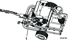
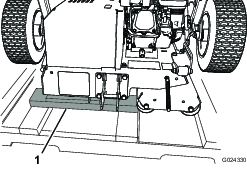
Whenever you need service, genuine Toro parts, or additional information, contact an Authorized Service Dealer or Toro Customer Service and have the model and serial numbers of your product ready. Figure 1 identifies the location of the model and serial numbers on the product. Write the numbers in the space provided.
This manual identifies potential hazards and has safety messages identified by the safety-alert symbol (Figure 2), which signals a hazard that may cause serious injury or death if you do not follow the recommended precautions.

This manual uses 2 words to highlight information. Important calls attention to special mechanical information and Note emphasizes general information worthy of special attention.
This product complies with all relevant European directives. For details, please see the separate product specific Declaration of Conformity (DOC) sheet.
It is a violation of California Public Resource Code Section 4442 or 4443 to use or operate the engine on any forest-covered, brush-covered, or grass-covered land unless the engine is equipped with a spark arrester, as defined in Section 4442, maintained in effective working order or the engine is constructed, equipped, and maintained for the prevention of fire.
Warning
CALIFORNIA
Proposition 65 Warning
The engine exhaust from this product contains chemicals known to the State of California to cause cancer, birth defects, or other reproductive harm.
Use of this product may cause exposure to chemicals known to the State of California to cause cancer, birth defects, or other reproductive harm.
Safety
This machine has been designed in accordance with EN ISO 12100:2010 and ANSI B71.4-2017.
Important: For CE required regulatory data, refer to the Declaration of Conformity supplied with the machine.
General Safety
This product is capable of causing personal injury. Always follow all safety instructions to avoid serious personal injury.
Using this product for purposes other than its intended use could prove dangerous to you and bystanders.
-
Read and understand the contents of this Operator’s Manual before starting the engine.
-
Do not put your hands or feet near moving components of the machine.
-
Do not operate the machine without all guards and other safety protective devices in place and working on the machine.
-
Keep bystanders and pets a safe distance away from the machine.
-
Keep children out of the operating area. Never allow children to operate the machine.
-
Stop the machine and shut off the engine before servicing, fueling, or unclogging the machine.
Improperly using or maintaining this machine can result in injury.
To reduce the potential for injury, comply with these safety instructions
and always pay attention to the safety-alert symbol  , which means Caution, Warning,
or Danger—personal safety instruction. Failure to comply with
these instructions may result in personal injury or death.
, which means Caution, Warning,
or Danger—personal safety instruction. Failure to comply with
these instructions may result in personal injury or death.
You can find additional safety information where needed throughout this Operator’s Manual.
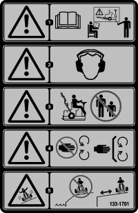
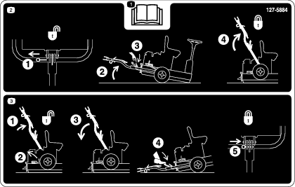
Safety and Instructional Decals
 |
Safety decals and instructions are easily visible to the operator and are located near any area of potential danger. Replace any decal that is damaged or missing. |


Setup
Installing the Transport Wheels
Parts needed for this procedure:
| Transport wheel | 2 |
-
Remove the lug nuts securing the wheel hubs to the shipping brackets (Figure 3). Also, remove the nuts threaded onto the stud of each wheel hub.
-
Carefully remove the shipping brackets from the crates.
-
Install the transport wheels onto the wheel hubs with the lug nuts. Hand-tighten the lug nuts.
Note: The lug nuts will be torqued at the completion of step 2.
-
Adjust the tire pressure to 103 kPa (15 psi).
Installing the Hitch Assembly
Parts needed for this procedure:
| Lock bracket | 1 |
| Bolt (M10 x 30 mm) | 4 |
| Lock washer (M10) | 4 |
| Washer (M10) | 6 |
| Nut (M10) | 4 |
| Hitch assembly | 1 |
| Bolt (M10 x 100 mm) | 1 |
| Locknut (M10) | 1 |
| Bolt (M12 x 100 mm) | 1 |
| Washer (M12) | 2 |
| Locknut (M12) | 1 |
| Spacer washer (when applicable) | 2 |
-
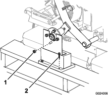
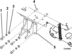
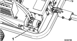
Install the lock bracket to the frame of the machine as shown in Figure 4.
Note: Torque the nuts to 52 N∙m (38 ft-lb).
-
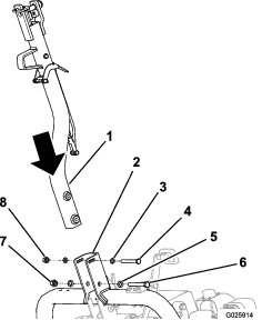
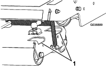
Secure the hitch to the hitch pivot bracket with the appropriate hardware; refer to Figure 5.
-
In the front holes, use a bolt (M10 x 100 mm), 2 washers (M10), and a locknut (M10).
-
In the rear holes, use a bolt (M12 x 100 mm), 2 washers (M12), and a locknut (M12).
-
If your machine has a third washer included with each bolt, use those washers as spacers between the hitch and the inside of the hitch pivot bracket (Figure 6).
Note: Use the holes in the hitch pivot bracket to match the hitch height of the tow-vehicle hitch.

-
-
Tighten the small bolt to 73 N∙m (54 ft-lb) and the large bolt to 126 N∙m (93 ft-lb).
-
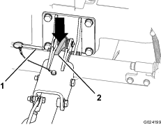
Push up on the hitch assembly until the latch lever is unlocked from the slide detent (Figure 7).
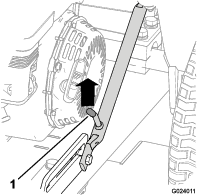
-
Pull the hitch down.
-
Step on the hitch pedal until the hitch locks into place (Figure 8).
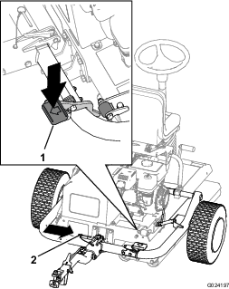
-
Insert the locking pin (Figure 8).
-
Torque the lug nuts on the transport wheels to 108 N∙m (80 ft-lb).
Removing the Machine from the Pallet
-
Remove the wood blocks at the hitch end of the pallet.
-
Place some wood boards on the ground at the end of the pallet.
Note: The height of the wood boards should be slightly lower than the pallet. You can use pieces removed from the sides and/or ends of the crate.
-
Carefully roll the machine off the pallet, onto the wood boards, and then to the ground.
Important: Ensure that the rollers do not contact the pallet as the machine drops to the ground.
-
Remove any remaining packaging.
Lubricating the Machine
Parts needed for this procedure:
| Lubricants (not included) | – |
Before you operate the machine, lubricate it to ensure proper operating characteristics; refer to Lubrication. Failure to properly lubricate the machine will result in premature failure of critical parts.
Product Overview
Note: Refer to your engine owner’s manual for complete control information.
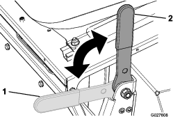
Parking Brake
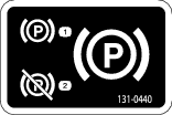
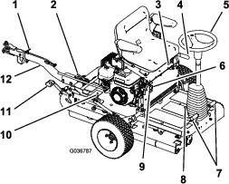
Engage the parking brake to allow the machine to start. To engage the parking brake (Figure 12), pull back on the parking-brake lever. To disengage it, push the lever forward.
Steering Wheel
Turn the steering wheel (Figure 10) clockwise to turn the machine in the forward direction.
Turn the steering wheel counterclockwise to turn the machine in the rearward direction.
Note: As the direction changes at the end of every run, you will need to practice with the machine to become accustomed to the steering.
The steering wheel controls the angle of the smoothing rollers, which in turn steer the machine. The amount the wheel can be turned is limited, so the turning circle of the machine is large.
Tilt-Steering Pedal
To tilt the steering wheel toward you, press the foot pedal (Figure 10) down, pull the steering tower toward you to the most comfortable position, and release the pedal.
Motion Pedals
The foot-operated motion pedals (Figure 10), located to either side of the base of the steering wheel, control the motion of the drive roller. The pedals are connected so that they cannot both be pressed down at the same time, you can press only 1 pedal at a time. If you press down the right pedal, the machine moves to the right, and if you press down the left pedal, the machine moves to the left. The further you press a pedal, the faster your speed in that direction.
Note: Come to a full stop before changing the direction of the machine; do not abruptly change the pedal direction. Doing so overstresses the traction drive line, resulting in premature failure of drive-line components. Actuate the pedals slowly and smoothly to avoid potential turf scuffing damage as well as drive-line component damage.When operating the machine on hills, ensure that the drive roller is on the downhill side for adequate traction. Failure to do so may result in turf damage.
Hitch Assembly
Use the hitch assembly (Figure 10) to tow the machine and to lower/raise the transport wheels.
Seat-Adjustment Lever
You can move the seat forward or backward. Rotate the seat-adjustment lever (Figure 10) upward and slide the seat forward or backward, then release the lever.
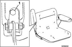
Armrest-Adjustment Bolts
You can adjust each armrest by turning the respective adjustment bolt (Figure 13).
Light Switch
Use the light switch to turn the lights on and off (Figure 10).
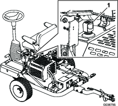
Hour Meter
The hour meter (Figure 10) indicates the total hours of machine operation.
Engine Controls
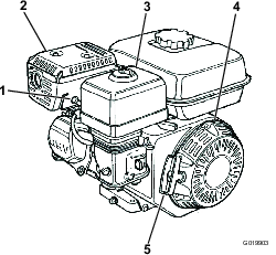
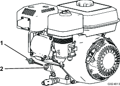
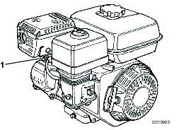
On/Off Switch
The On/Off switch (Figure 14) allows the operator of the machine to start and shut off the engine. This switch is located on the front of the engine. Rotate the On/Off switch to the ON position to start and run the engine. Rotate the On/Off switch to the OFF position to shut off the engine.
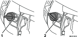
Choke Lever
The choke lever (Figure 15) is required when starting a cold engine. Before pulling the recoil-start handle, move the choke lever to the CLOSED position. Once the engine is running, move the choke lever to the OPEN position. Do not use the choke if the engine is already warmed up or if the air temperature is high.
Throttle Lever
The throttle lever (Figure 15) is located next to the choke control; it controls the speed of the engine and therefore controls the speed of the machine. For best rolling performance, set this control to the FAST position.
Fuel-Shutoff Valve
The fuel-shutoff valve (Figure 15) is located underneath the choke lever. Move it to the open position before attempting to start the engine. Once you have finished using the machine and you have turned the engine off, move the fuel-shutoff valve to the CLOSED position.
Recoil-Start Handle
To start the engine, pull the recoil-start handle (Figure 11) quickly to turn the engine over. The controls on the engine described above must all be set correctly for the engine to start.
Oil-Level Switch
The oil-level switch is located inside the engine; it prevents the engine from running if the oil level falls below the safe operating limit.
| Weight | 308 kg (679 lb) |
| Length | 136 cm (53.5 inches) |
| Width | 122 cm (48.0 inches) |
| Height | 107 cm (42.2 inches) |
| Maximum speed | 12.8 km/h (8 mph) @ 3600 rpm |
Attachments/Accessories
A selection of Toro approved attachments and accessories is available for use with the machine to enhance and expand its capabilities. Contact your Authorized Service Dealer or authorized Toro distributor or go to www.Toro.com for a list of all approved attachments and accessories.
To ensure optimum performance and continued safety certification of the machine, use only genuine Toro replacement parts and accessories. Replacement parts and accessories made by other manufacturers could be dangerous, and such use could void the product warranty.
Operation
Note: Determine the left and right sides of the machine from the normal operating position.
Before Operation Safety
General Safety
-
Never allow children or untrained people to operate or service the machine. Local regulations may restrict the age of the operator. The owner is responsible for training all operators and mechanics.
-
Become familiar with the safe operation of the equipment, operator controls, and safety signs.
-
Know how to stop the machine and engine quickly.
-
Check that operator-presence controls, safety switches, and shields are attached and functioning properly. Do not operate the machine unless they are functioning properly.
-
Before operating, always inspect the machine to ensure that the components and fasteners are in good working condition. Replace worn or damaged components and fasteners.
-
Inspect the area where you will use the machine and remove all objects that the machine could throw.
Fuel Safety
-
Use extreme care in handling fuel. It is flammable and its vapors are explosive.
-
Extinguish all cigarettes, cigars, pipes, and other sources of ignition.
-
Use only an approved fuel container.
-
Do not remove the fuel cap or fill the fuel tank while the engine is running or hot.
-
Do not add or drain fuel in an enclosed space.
-
Do not store the machine or fuel container where there is an open flame, spark, or pilot light, such as on a water heater or other appliance.
-
If you spill fuel, do not attempt to start the engine; avoid creating any source of ignition until the fuel vapors have dissipated.
Preparing to Use the Machine
-
Clear any debris from above and underneath the machine.
-
Ensure that all scheduled maintenance has been completed.
-
Ensure that all guards and covers are in place and firmly attached.
-
Check the level of the engine oil.
-
Ensure that there is fuel in the fuel tank.
-
Ensure that the parking brake is engaged.
-
Lift the transport wheels clear of the ground and ensure that they are locked in place.
Checking the Hydraulic Hoses and Fittings
Check the hydraulic system for leaks, loose mounting supports, wear, loose fittings, weather deterioration, and chemical deterioration. Make all necessary repairs before operating the machine.
Warning
Hydraulic fluid escaping under pressure can penetrate skin and cause injury.
-
Seek immediate medical attention if fluid is injected into skin.
-
Make sure that all hydraulic fluid hoses and lines are in good condition and all hydraulic connections and fittings are tight before applying pressure to the hydraulic system.
-
Keep your body and hands away from pinhole leaks or nozzles that eject high-pressure hydraulic fluid.
-
Use cardboard or paper to find hydraulic leaks.
-
Safely relieve all pressure in the hydraulic system before performing any work on the hydraulic system.
Checking the Level of the Engine Oil
| Maintenance Service Interval | Maintenance Procedure |
|---|---|
| Before each use or daily |
|
Note: The best time to check the engine oil is when the engine is cool before it has been started for the day. If it has already been run, allow the oil to drain back down to the sump for at least 10 minutes before checking it.
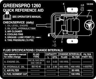
Crankcase Capacity: 0.60 L (0.63 US qt)
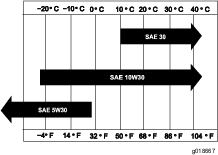
Type: APl service classification SL, SM, SN, or higher
Viscosity: select according to ambient temperature; refer to Figure 16.
-
Position the machine on a flat surface so that the engine is level.
-
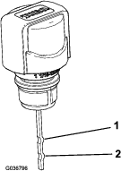
Shut off the engine, wait for it to cool, and clean the area around the oil-filler cap/dipstick (Figure 17).
-
Remove the oil-filler cap/dipstick by rotating it counterclockwise.
-
Wipe the oil-filler cap/dipstick clean and insert it into the filler port.
Note: Do not screw the dipstick into the port.
-
Remove the dipstick and check the oil level.
Note: If the oil level is near or below the lower-limit mark on the dipstick, add only enough oil to raise level to the upper-limit mark (bottom edge of the oil-fill hole); refer to Figure 18. Check the oil level again. Do not overfill the crankcase.
-
Install the oil-filler cap/dipstick and wipe up any spilled oil.
Note: Running the engine with the oil level at the lower limit may induce nuisance engine shutdowns in operating situations where the machine is switching direction on an incline or descent.
Checking the Level of the Hydraulic Fluid
| Maintenance Service Interval | Maintenance Procedure |
|---|---|
| Before each use or daily |
|
The hydraulic system is filled at the factory with high-quality hydraulic fluid. Check the level of the hydraulic fluid before the engine is first started and daily thereafter.
Note: Before working on any part of the hydraulic drive system, shut off the engine to depressurize the system. Before starting the engine after hydraulic system maintenance, and pressurizing the hydraulic lines, check all hoses and connectors for damage and to ensure that they are tight. Replace any damaged hoses and tighten any loose couplings as required.
Recommended Hydraulic Fluid: Toro Premium All Season Hydraulic Fluid (Available in 5 US gallon pails or 55 US gallon drums. Refer to the parts catalog or contact your Authorized Toro Distributor for part numbers.)
Alternative fluids: If the Toro fluid is not available, other conventional, petroleum-based fluids may be used, provided they meet all of the following material properties and industry specifications. Check with your oil supplier to see whether the oil meets these specifications.
Note: Toro will not assume responsibility for damage caused by improper substitutions, so use only products from reputable manufacturers who will stand behind their recommendation.
| High Viscosity Index/Low Pour Point Anti-wear Hydraulic Fluid, ISO VG 46 Multigrade | |
| Material Properties: | |
| Viscosity, ASTM D445 | cSt @ 40°C (104°F) 44 to 48cSt @ 100°C (212°F) 7.9 to 9.1 |
| Viscosity Index ASTM D2270 | 140 or higher |
| Pour Point, ASTM D97 | -37°C to -45°C (-34°F to -49°F) |
| FZG, Fail stage | 11 or better |
| Water content (new fluid): | 500 ppm (maximum) |
| Industry Specifications: | |
| Vickers I-286-S, Vickers M-2950-S, Denison HF-0, Vickers 35 VQ 25 (Eaton ATS373-C) | |
The proper hydraulic fluids must be specified for mobile machinery (as opposed to industrial plant usage), multiweight-type, with ZnDTP or ZDDP anti-wear additive package (not an ashless-type fluid).
Note: Many hydraulic fluids are almost colorless, making it difficult to spot leaks. A red dye additive for the hydraulic system fluid is available in 20 ml (2/3 fl oz) bottles. One bottle is sufficient for 15 to 22 L (4 to 6 US gallons) of hydraulic fluid. Order Part No. 44-2500 from your Authorized Toro Distributor.
-
Position the machine on a level surface, shut off the engine, and engage the parking brake.
-
Pull back on the seat latch, and tip the seat forward (Figure 19).
-
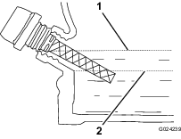
Remove the hydraulic-tank cap and check the fluid level on the dipstick (Figure 20).
Note: The fluid level should be between the upper limit and the lower limit on the dipstick (Figure 21).
-
If the fluid level is low, add enough fluid to raise it to the proper level.
-
Install the tank cap.
-
Wipe up any spilled fluid.
-
Lower and latch the seat.
Checking the Tire Pressure
| Maintenance Service Interval | Maintenance Procedure |
|---|---|
| Before each use or daily |
|
Make sure that the transport tires are inflated to 103 kPa (15 psi).
Filling the Fuel Tank
-
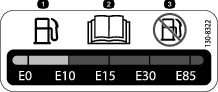
For best results, use only clean, fresh (less than 30 days old), unleaded gasoline with an octane rating of 87 or higher ((R+M)/2 rating method).
-
Ethanol: Gasoline with up to 10% ethanol (gasohol) or 15% MTBE (methyl tertiary butyl ether) by volume is acceptable. Ethanol and MTBE are not the same. Gasoline with 15% ethanol (E15) by volume is not approved for use. Never use gasoline that contains more than 10% ethanol by volume, such as E15 (contains 15% ethanol), E20 (contains 20% ethanol), or E85 (contains 85% ethanol). Using unapproved gasoline may cause performance problems and/or engine damage, which may not be covered under warranty.
-
Do not use gasoline containing methanol.
-
Do not store fuel either in the fuel tank or fuel containers over the winter unless a fuel stabilizer is used
-
Do not add oil to gasoline.
Fuel-Tank Capacity: 3.6 L (0.95 US gallons)
-
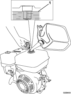
Clean around the fuel-tank cap and remove the cap from the tank (Figure 22). Using unleaded (87 pump octane minimum) gasoline, fill the fuel tank to approximately 25 mm (1 inch) below the top of the tank to allow for fuel expansion.
Important: Do not overfill the tank. Adding fuel in excess of the prescribed level will result in engine failure due to saturation of the vapor recovery system, resulting in engine performance failure. This is not a warrantable failure and will require replacement of the fuel-tank cap.
Important: Never use methanol, gasoline containing methanol, gasohol containing more than 10% ethanol, gasoline additives, premium gasoline, or white gas because the fuel system could be damaged. Do not mix oil with gasoline.
-
Install the fuel-tank cap and wipe up any spilled fuel.
During Operation Safety
General Safety
-
The owner/operator can prevent and is responsible for accidents that may cause personal injury or property damage.
-
Wear appropriate clothing, including eye protection; slip-resistant, substantial foot protection; long pants; and hearing protection. Tie back long hair and do not wear loose jewelry.
-
Do not operate the machine while ill, tired, or under the influence of alcohol or drugs.
-
Never carry passengers on the machine and keep bystanders and pets away from the machine during operation.
-
Operate the machine only in good visibility to avoid holes or hidden hazards.
-
Avoid operating on wet grass. Reduced traction could cause the machine to slide.
-
Before you start the engine, ensure that all drives are in neutral, the parking brake is engaged, and you are in the operating position.
-
Look behind and down before backing up to be sure of a clear path.
-
Use care when approaching blind corners, shrubs, trees, or other objects that may obscure your vision.
-
Do not operate near drop-offs, ditches, or embankments. The machine could suddenly roll over if an edge gives way.
-
Stop the machine and inspect the attachment after striking an object or if there is an abnormal vibration in the machine. Make all necessary repairs before resuming operation.
-
Slow down and use caution when making turns and crossing roads and sidewalks with the machine. Always yield the right-of-way.
-
Never run an engine in an area where exhaust gasses are enclosed.
-
Never leave a running machine unattended.
-
Before leaving the operating position, do the following:
-
Park the machine on level ground.
-
Engage the parking brake.
-
Shut off the engine.
-
Wait for all moving parts to stop.
-
-
Do not operate the machine when there is the risk of lightning.
-
Do not use the machine as a towing vehicle.
-
Use accessories, attachments, and replacement parts approved by The Toro® Company only.
-
Keep hands and feet away from the rollers.
-
Use care when connecting and disconnecting the machine to and from the tow vehicle.
Slope Safety
-
Establish your own procedures and rules for operating on slopes. These procedures must include surveying the site to determine which slopes are safe for machine operation. Always use common sense and good judgment when performing this survey.
-
Slopes are a major factor related to loss of control and rollover accidents, which can result in severe injury or death. The operator is responsible for safe slope operation. Operating the machine on any slope requires extra caution.
-
Operate the machine at a lower speed when you are on a slope.
-
If you feel uneasy operating the machine on a slope, do not do it.
-
Watch for holes, ruts, bumps, rocks, or other hidden objects. Uneven terrain could overturn the machine. Tall grass can hide obstacles.
-
Choose a low ground speed so that you do not need to stop or shift while on a slope.
-
A rollover can occur before the tires lose traction.
-
Avoid operating the machine on wet grass. Rollers may lose traction, regardless of whether the brakes are available and functioning.
-
Avoid starting, stopping, or turning the machine on a slope.
-
Keep all movement on slopes slow and gradual. Do not suddenly change the speed or direction of the machine.
Starting the Engine
Note: Make sure that the spark-plug wire is connected to the spark plug.
-
Ensure that the parking brake is engaged and that the motion pedals are in the NEUTRAL position.
-
Turn the On/Off switch to the ON position.
-
Turn the fuel-shutoff valve to the OPEN position.
-
Move the choke lever to the ON position when starting a cold engine.
Note: The choke may not be required when starting a warm engine.
-
Move the throttle control to the FAST position.
-
Stand at the rear of the machine, pull the recoil-start handle out until positive engagement results; then pull it vigorously to start the engine.
Important: Do not pull the recoil rope to the limit or let go of the starter handle when the rope is pulled out, because the rope may break or the recoil assembly may be damaged.
-
When the engine has started, push the choke lever to the OFF position.
-
Move the throttle lever to the FAST position, for best roller performance.
Shutting Off the Engine
-
After operating the machine, return the motion pedals to the NEUTRAL position and engage the parking brake.
-
Turn the engine speed to idle, and allow it to run for 10 to 20 seconds.
-
Turn the On/Off switch to the OFF position.
-
Turn the fuel-shutoff valve to the CLOSED position.
Checking the Safety-Interlock System
| Maintenance Service Interval | Maintenance Procedure |
|---|---|
| Before each use or daily |
|
Caution
If the safety-interlock switches are disconnected or damaged, the machine could operate unexpectedly, causing personal injury.
-
Do not tamper with the interlock switches.
-
Check the operation of the interlock switches daily, and replace any damaged switches before operating the machine.
Important: If the safety-interlock system does not operate as described below, have an Authorized Toro Distributor repair it immediately.
-
Engage the parking brake, ensure that the motion pedals are in the NEUTRAL position, and start the engine.
-
Sit on the seat.
-
With the parking brake engaged, gently press a motion pedal down; the engine should shut off after approximately 1 second.
-
With the engine running and the brake disengaged, stand up and verify that the engine shuts off after 1 second.
Note: The safety-interlock system is also designed to shut off the engine if the operator rises off the seat while the machine is moving.
After Operation Safety
-
Park the machine on a level surface; engage the parking brake or chock the wheels as required; shut off the engine; and wait for all movement to stop before leaving the machine.
-
Clean grass and debris from the muffler and engine compartment to help prevent fires. Clean up oil or fuel spills.
-
Allow the engine to cool before storing the machine in any enclosure.
-
Shut off the fuel before storing or transporting the machine.
-
Never store the machine or fuel container where there is an open flame, spark, or pilot light, such as on a water heater or on other appliances.
-
Keep all parts of the machine in good working condition and all hardware tightened.
-
Replace all worn, damaged, or missing decals.
Using the Hitch Lock
Connecting the Machine to the Tow Vehicle
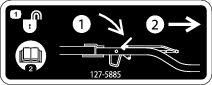
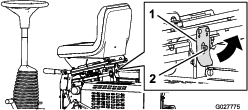
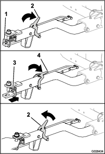
Push down on the hitch-lock lever while inserting the hitch assembly onto the tow-vehicle hitch. Release the lever when the hitch and the hitch assembly are aligned (Figure 23).
Important: Ensure that the lever returns to the Up position and that the hitch and the hitch assembly are engaged.
Disconnecting the Machine from the Tow Vehicle
Park the machine on level ground and chock the wheels.
Push down on the hitch-lock lever while removing the hitch assembly from the tow-vehicle hitch (Figure 23). Release the latch when the hitch and the hitch assembly are disengaged.
Transporting the Machine
-
Drive the machine to the transport vehicle.
-
Engage the parking brake.
-
Move the throttle lever to the low-speed position, and allow the engine to run for 10 to 20 seconds.
-
Turn the On/Off switch to the OFF position.
-
Turn the fuel-shutoff valve to the CLOSED position.
-
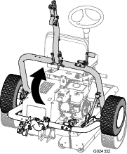
Raise the machine onto the transport wheels as follows:
-
Lower the machine onto the rollers as follows:
Operating the Machine
-
Ensure that the parking brake is engaged.
-
Sit on the operator seat, taking care not to contact the motion pedals as you sit down.
-
Adjust the seat and the steering wheel to a comfortable operating position.
-
Disengage the parking brake.
-
Hold onto the steering wheel, and slowly press either the left or right motion pedal with your corresponding foot, in whichever direction you wish to move.
Note: The further you press the pedal, the faster you will travel in that direction.
-
To stop the machine, release the foot pedal.
Note: As you become familiar with the machine, you will get the feel for when you should release the foot pedal, which will be prior to where you want to finish the run, as the machine continues to roll for a short time after you release the pedal. As you come to a complete stop, gently press the other foot pedal for your return pass.
Note: Do not press the foot pedals too quickly; this will result in possible skidding and scuffing of the turf under the drive roller as well as damage to the drive system. You should always operate the foot pedals in a controlled manner.
-
Turn the steering wheel clockwise to turn the machine in the forward direction.
Turn the steering wheel counterclockwise to turn the machine in the rearward direction.
Note: As the direction changes at the end of every run, you will need to practice with the machine to become accustomed to the steering.
Important: To stop the machine in an emergency, press the other pedal to the NEUTRAL position. As an example, with the right pedal pressed and traveling to the right, press the left pedal to the NEUTRAL position to bring the machine to a stop. This action must be firm but not sudden, as it may cause the machine to tip sideways.
-
Disengage the parking brake.
-
Before dismounting the machine, make sure that it is parked on a level surface.
Hauling the Machine
-
Use full-width ramps for loading the machine onto a trailer or truck.
-
Tie the machine down securely.
Operating Tips
-
When operating the machine on hills, ensure that the drive roller is on the downhill side for adequate traction. Failure to do so may result in turf damage.
-
For the best rolling effect, periodically remove any buildup that accumulates on the rollers.
Maintenance
Recommended Maintenance Schedule(s)
| Maintenance Service Interval | Maintenance Procedure |
|---|---|
| After the first 5 hours |
|
| After the first 20 hours |
|
| Before each use or daily |
|
| After each use |
|
| Every 50 hours |
|
| Every 100 hours |
|
| Every 300 hours |
|
| Every 400 hours |
|
| Before storage |
|
| Yearly |
|
Important: Refer to your engine owner's manual for additional maintenance procedures.
Note: To obtain an electrical schematic or a hydraulic schematic for your machine, visit www.Toro.com.
Warning
If you are not careful with hazardous substances, they can cause serious personal injury.
-
Read the labels and instructions for the materials that you use.
-
Wear the necessary personal protective safety equipment, and use hazardous substances carefully.
The following fluids are identified as being hazardous:
| Substances | Assessed Risk |
| Gasoline | Low |
| Lubricating oil | Low |
| Hydraulic fluid | Low |
| Grease | Low |
-
When using any of the above fluids, wear eye protection and gloves, and be careful to prevent spills.
-
Avoid contact with skin; wash off spills with soap and water.
-
Avoid contact with eyes; wash with running water and seek medical attention if symptoms persist.
-
Avoid ingestion; if swallowed seek medical attention.
-
Keep clear of high-pressure fluid escaping from pinholes, cracked connections, etc. High-pressure fluid can penetrate the skin. Seek immediate medical advice if any fluid is injected into the skin.
-
Always use a piece of cardboard or paper when searching for leaks.
-
Waste products must not be allowed to contaminate surface water, drains, or sewer systems.
Important: Prevent environmental damage. Dispose of hazardous substances correctly. When disposing of hazardous waste products, take them to an authorized disposal site.
Notation for Areas of Concern
| Inspection performed by: | ||
| Item | Date | Information |
| 1 | ||
| 2 | ||
| 3 | ||
| 4 | ||
| 5 | ||
| 6 | ||
| 7 | ||
| 8 | ||
Pre-Maintenance Procedures
Do not tilt the machine unless it is necessary. If you tilt the machine, engine oil could enter the cylinder head of the engine, and hydraulic fluid could leak from the cap located on top of the tank. These leaks may result in expensive repairs to the machine. To perform service under the deck, lift the machine with a hoist or a small crane.
Maintenance Safety
-
Before adjusting, cleaning, repairing, or leaving the machine, do the following:
-
Park the machine on a level surface.
-
Move the throttle switch to the low-idle position.
-
Ensure that the traction is in neutral.
-
Engage the parking brake.
-
Shut off the engine.
-
Wait for all moving parts to stop.
-
Allow machine components to cool before performing maintenance.
-
-
If possible, do not perform maintenance while the engine is running. Keep away from moving parts.
-
Use jack stands to support the machine or components when required.
-
Carefully release pressure from components with stored energy.
Lubrication
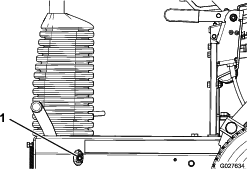
Lubricating the Drive-Roller Bearing
| Maintenance Service Interval | Maintenance Procedure |
|---|---|
| Before each use or daily |
|
Grease Type: No. 2 lithium grease
-
Wipe the area clean so that foreign matter cannot be forced into the bearing.
-
Pump grease into the grease fitting as shown in Figure 29.
-
Wipe up any excess grease.
Important: After greasing, run the machine off the turf somewhere briefly to disperse any excess lubricant, to avoid damaging the turf.
Engine Maintenance
Engine Safety
-
Shut off the engine before checking the oil or adding oil to the crankcase.
-
Do not change the governor speed or overspeed the engine.
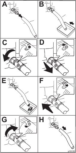
Changing the Engine Oil
| Maintenance Service Interval | Maintenance Procedure |
|---|---|
| After the first 20 hours |
|
| Every 100 hours |
|
-
Start and run the engine for a few minutes to warm the engine oil; then shut off the engine.
-
Raise the machine onto the transport wheels.
-
Tilt the machine so that the end of the machine with the engine is closer to the ground, and support the other end to hold it in this position.
-
Install the drain hose onto the drain valve (Figure 30).
-
Place the other end of the hose into a suitable container for oil (Figure 30).
-
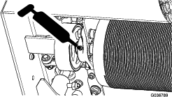
Turn the oil drain valve 1/4 turn counterclockwise to start draining the oil (Figure 30).
-
When all the oil is drained, turn the oil drain valve 1/4 turn clockwise to close the valve (Figure 30).
-
Remove the drain hose and wipe any oil that may have spilled.
-
Fill the crankcase with the specified oil; refer to Checking the Level of the Engine Oil.
-
Dispose of the oil properly. Recycle it according to local codes.
Servicing the Air Cleaner
| Maintenance Service Interval | Maintenance Procedure |
|---|---|
| Before each use or daily |
|
| Every 50 hours |
|
| Every 300 hours |
|
-
Disconnect the spark-plug wire from the spark plug.
-
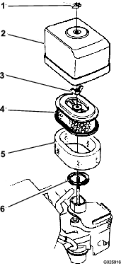
Remove the wing nut securing the air-cleaner cover to the air cleaner, and remove the cover (Figure 31).
-
Clean the cover thoroughly.
-
Remove the wing nut from the air filter, and remove the filter (Figure 31).
-
Remove the foam filter from the paper filter(Figure 31).
-
Inspect both air-filter elements, and replace them if they are damaged.
Note: Always replace the paper air-filter element at the scheduled interval.
-
Clean the foam element as follows:
-
Wash the foam element in a solution of liquid soap and warm water.
Note: Squeeze the element to remove the dirt, but do not twist it, because the foam may tear.
-
Dry it by wrapping it in a clean rag.
Note: Squeeze the rag and foam element to dry the element, but do not twist it, because the foam may tear.
-
Saturate the element with clean engine oil.
Note: Squeeze the element to remove excess oil and to distribute the oil thoroughly. The foam element should be damp with oil.
-
-
Clean the paper element by tapping the filter element several times on a hard surface to remove the dirt.
Note: Never brush dirt off the element or use compressed air to remove dirt; brushing forces dirt into the fibers, and compressed air will damage the paper filter.
-
Install the foam element, the paper element, and the air-cleaner cover.
Important: Do not operate the engine without the air-cleaner elements, because extreme engine wear and damage will likely result.
Servicing the Spark Plug
| Maintenance Service Interval | Maintenance Procedure |
|---|---|
| Every 100 hours |
|
| Every 300 hours |
|
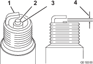
Type: NGK BPR6ES spark plug or equivalent
Air Gap: 0.70 to 0.80 mm (0.028 to 0.031 inch); refer to Figure 33
-
Disconnect the spark-plug wire from the spark plug (Figure 32).
-
Clean around the spark plug, and remove the plug from the cylinder head.
Important: Replace a cracked, fouled, or dirty spark plug. Do not sand blast, scrape, or clean the electrodes, because engine damage could result from grit entering the cylinder.
-
Set the air gap to 0.70 to 0.80 mm (0.028 to 0.031 inch)(Figure 33).
-
Install the correctly gapped spark plug carefully by hand, to avoid cross-threading.
-
After the spark plug is seated, tighten it with a spark-plug wrench to compress the sealing washer.
-
When installing a new spark plug, tighten it 1/2 turn after the spark plug seats, to compress the washer.
-
When installing the original spark plug, tighten it 1/8 to 1/4 turn after the spark plug seats, to compress the washer.
Note: A loose spark plug can overheat and damage the engine. Overtightening the spark plug can damage the threads in the cylinder head.
-
-
Connect the spark-plug wire to the spark plug.
Checking and Adjusting the Valve Clearance
| Maintenance Service Interval | Maintenance Procedure |
|---|---|
| Every 300 hours |
|
Important: Refer to your engine owner’s manual.
Fuel System Maintenance
Cleaning the Sediment Cup
| Maintenance Service Interval | Maintenance Procedure |
|---|---|
| Every 100 hours |
|
Danger
In certain conditions, fuel is extremely flammable and highly explosive. A fire or explosion from fuel can burn you and others and can damage property.
-
Fill the fuel tank outdoors, in an open area, when the engine is cold. Wipe up any fuel that spills.
-
Do not fill the fuel tank completely full. Add fuel to the fuel tank until the level is 25 mm (1 inch) below the top of the tank. This empty space in the tank allows the fuel to expand.
-
Never smoke when handling fuel, and stay away from an open flame or where fuel fumes may be ignited by a spark.
-
Store fuel in an approved container and keep it out of the reach of children. Do not buy more than a 30-day supply of fuel.
-
Always place fuel containers on the ground away from your vehicle before filling.
-
Do not fill fuel containers inside a vehicle or on a truck or trailer bed, because interior carpets or plastic truck-bed liners may insulate the container and slow the loss of any static charge.
-
When practical, remove fuel-powered equipment from the truck or trailer and fuel the equipment with the wheels on the ground. If this is not possible, then fuel such equipment on a truck or trailer from a portable container rather than from a fuel-dispenser nozzle.
-
If you must use a fuel-dispenser nozzle, keep the nozzle in contact with the rim of the fuel tank or container opening at all times until fueling is complete.
-
Move the fuel-shutoff valve to the OFF position, then remove the fuel sediment cup and O-ring (Figure 34).
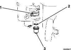
-
Wash the sediment cup and O-ring in nonflammable solvent, and dry them thoroughly.
-
Place the O-ring in the fuel-shutoff valve and install the sediment cup. Tighten the sediment cup securely.
Drive System Maintenance
Hydraulic System Safety
-
Seek immediate medical attention if fluid is injected into skin. Injected fluid must be surgically removed within a few hours by a doctor.
-
Ensure that all hydraulic-fluid hoses and lines are in good condition and all hydraulic connections and fittings are tight before applying pressure to the hydraulic system.
-
Keep your body and hands away from pinhole leaks or nozzles that eject high-pressure hydraulic fluid.
-
Use cardboard or paper to find hydraulic leaks.
-
Safely relieve all pressure in the hydraulic system before performing any work on the hydraulic system.
Changing the Hydraulic Fluid and Filter
| Maintenance Service Interval | Maintenance Procedure |
|---|---|
| After the first 20 hours |
|
| Every 400 hours |
|
Important: Use only Toro Premium All Season Hydraulic Fluid (ISO VG 46) or an equivalent fluid. Other fluids could cause system damage.
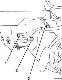
-
Place a drain pan under the hydraulic-tank drain plug (Figure 35).
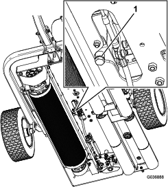
-
Remove the drain plug from the bottom of the tank (Figure 35).
-
When the fluid has drained completely, install the drain plug.
-
Clean the area around the filter mounting area.
-
Place a drain pan under the filter and remove the filter (Figure 36).
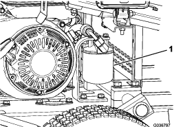
-
Fill the replacement filter with the appropriate hydraulic fluid.
-
Lubricate the sealing gasket, install the filter by hand until the gasket contacts the filter head, then tighten it 3/4 turn further.
Note: The filter should now be sealed.
-
Remove the hydraulic-tank cap (Figure 20).
-
Fill the tank with the proper fluid; refer to Checking the Level of the Hydraulic Fluid.
-
Install the tank cap.
-
Wipe up any spilled fluid.
-
Start the machine and run it at low idle for 3 to 5 minutes to circulate the fluid and remove any air trapped in the system.
-
Shut off the engine, check the level of the hydraulic fluid, and add fluid if necessary.
-
Lower and latch the seat.
-
Dispose of the fluid and the filter according to local codes.
Brake Maintenance
Checking and Adjusting the Parking Brake
| Maintenance Service Interval | Maintenance Procedure |
|---|---|
| Before each use or daily |
|
Ensure that the parking brake prevents the machine from rolling when it is parked.
Adjust the parking brake as follows:
-
To increase the brake force, tighten the brake locknut (Figure 37).
-
To decrease the brake force, loosen the brake locknut (Figure 37).
Note: Ensure that the brake fully disengages when the brake handle is in the disengaged position.
Storage
-
Remove grass clippings, dirt, and grime from the external parts of the entire machine, especially the rollers and the engine. Clean dirt and chaff from the outside of the cylinder-head fins and the blower housing on the engine.
Important: You can wash the machine with mild detergent and water. Do not pressure wash the machine. Avoid excessive use of water, especially near the engine.
-
For long-term storage (more than 90 days) add stabilizer/conditioner additive to fuel in the tank.
-
Run the engine to distribute the conditioned fuel through the fuel system for 5 minutes.
-
Either shut off the engine, allow it to cool, and drain the fuel tank, or operate the engine until it shuts off.
-
Start the engine and run it until it shuts off. Repeat the procedure with the choke on until the engine does not start again.
-
Dispose of fuel properly. Recycle it according to local codes.
-
-
Check and tighten all bolts, nuts, and screws. Repair or replace any part that is worn or damaged.
-
Paint all scratched or bare metal surfaces. Paint is available from your authorized Toro distributor.
-
Store the machine in a clean, dry garage or storage area. Cover the machine to protect it and keep it clean.