

Maintenance
Adjusting the Track Tension
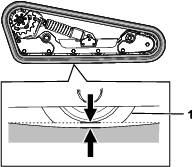
Lift/support 1 side of the machine and using the weight of the track, verify that the gap between the bottom of the lip of the road wheel and the track is 13 mm (1/2 inch) as shown in Figure 24. If it is not, adjust the track tension using the following procedure.
-
Park the machine on a level surface, engage the parking brake, and lower the loader arms.
-
Shut off the engine and remove the key.
-
Raise the side of the machine that you are adjusting so that the track is off the ground.
-
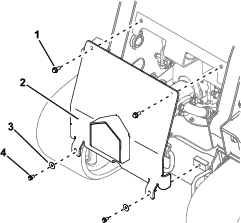
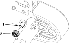
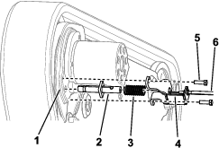
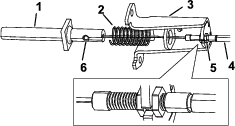
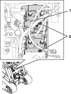
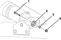
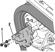
Remove the locking bolt, spacer, and nut (Figure 25).
-
Using a 1/2 inch drive ratchet, turn the tensioning screw until the track gap is 13 mm (1/2 inch) as shown in Figure 24.
Note: Turning the screw counter-clockwise tightens the track; turning the screw clockwise loosens the track.
-
Align the closest notch in the tension screw to the locking-bolt hole and secure the screw with the locking bolt and nut (Figure 25).
-
Repeat the procedure for the other track.
-
Drive the machine, then park the machine on a level surface, engage the parking brake, shut off the engine, and remove the key.
-
Verify that the track deflection is 13 mm (1/2 inch) as shown in Figure 24. Adjust if necessary.
Replacing the Tracks
Replace the tracks when they are badly worn.
Removing the Tracks
-
Remove any attachments.
-
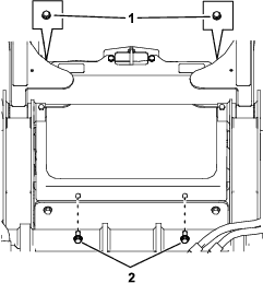
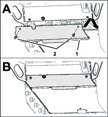
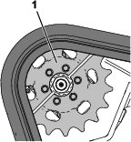
Park the machine on a level surface, ensuring that only 1 sprocket half is engaged with the track (Figure 26).
-
Engage the parking brake.
-
Lower the loader arms so that they are approximately 20 to 25 cm (8 to 10 inches) above the frame.
-
Shut off the engine and remove the key.
-
Lift the side of the machine with the track you are replacing. Support the machine using jack stands.
Note: Use jack stands rated for your machine.
Warning
Mechanical or hydraulic jacks may fail to support the machine and cause serious injury.
Use jack stands when supporting the machine.
-
Remove the locking bolt, spacer, and nut (Figure 25).
-
Using a 1/2-inch drive ratchet, release the drive tension by turning the tensioning screw clockwise (Figure 25 and Figure 27).
-
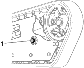
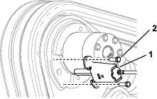
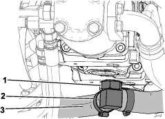
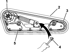
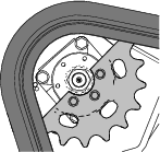
Remove the 3 bolts securing the sprocket half that is not engaged with the track (Figure 28).
-
Start the machine and disengage the parking brake.
-
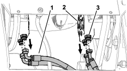
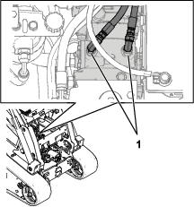
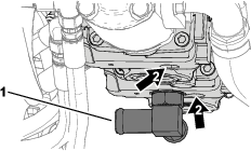
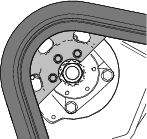
Move the traction control forward until the other half of the drive sprocket is not engaged with the track (Figure 29).
-
Engage the parking brake, shut off the engine, and remove the key.
-
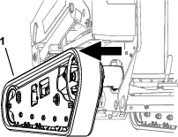
Remove the track from the track frame, drive hub, then front wheel.
Installing the Tracks
-
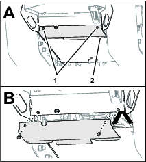
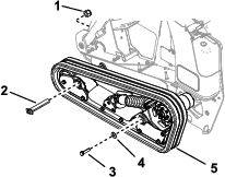
Wrap the new track around the front wheel, then wrap the track around the drive hub on the side without the sprocket (Figure 27).
-
Push the track under and between the road wheels and wrap it around the lower frame (Figure 27).
Note: Ensure that the road wheels are centered on the track.
-
Start the engine and disengage the parking brake.
-
Move the traction control forward until the drive sprocket half engages with the track (Figure 30).
-
Engage the parking brake, shut off the engine, and remove the key.
-
Apply thread-locking compound to the bolts of the drive sprocket half that you removed and install the sprocket half (Figure 28). Torque the bolts to 95 to 115 N∙m (70 to 85 ft-lb).
-
Using a 1/2 inch drive ratchet, turn the tensioning screw counter-clockwise until the track deflection is 13 mm (1/2 inch) as shown in Figure 24.
-
Align the closest notch in the tension screw to the locking bolt hole and secure the screw with the locking bolt, spacer, and nut.
-
Lower the machine to the ground.
-
Repeat the procedure to replace the other track.
-
Drive the machine, then park the machine on a level surface, engage the parking brake, shut off the engine, and remove the key.
-
Verify that the track deflection is 13 mm (1/2 inch) as shown in Figure 24.